Jun 3, 1994 - Materials Department, Ecole des Mines de Saint-Etienne, 158 Cours Fauriel, 42023 Saint-Etienne CEDEX 2, France. (Received 2 February ...
980 J. Appl. Cryst. (1994). 27, 980--987
Improved X-ray and Electron Diffraction Methods for Twin Determination in Hexagonal Crystals BY N. CHENEAU-SP,~TH, R. Y. FILLIT AND J. H. DRIVER
Materials Department, Ecole des Mines de Saint-Etienne, 158 Cours Fauriel, 42023 Saint-Etienne CEDEX 2, France (Received 2 February 1994; accepted i 3 June 1994)
Abstract Two improved methods of characterizing twin orientations in deformed crystals have been developed and compared; the back-scattered Kikuchi electron diffraction method in a standard scanning electron microscope and a new high-resolution X-ray pole-figure technique. Comparative tests on titanium and magnesium crystals deformed in plane strain compression up to high strains demonstrate their complementary features. The backscattered Kikuchi diffraction technique, which combines imaging and microdiffraction, is well adapted to localized twin-orientation studies in both single and polycrystals after careful surface preparation. The high-resolution X-ray pole figures can be used for more quantitative studies of twinned volume fractions, including very fine twins, in crystallographically oriented samples such as deformed single crystals or large-grained polycrystals.
1. Introduction The purpose of this paper is to describe and compare improved electron and X-ray diffraction methods of determining the twinning systems in plastically deformed crystals and polycrystals of hexagonal metals. It is well known that the number of slip systems in hexagonal metals is insufficient to accommodate generalized deformation modes and that mechanical twinning therefore plays an important role in both plastic forming operations and the rupture mechanisms of this class of material. The classical methods of twin determination, such as optical and transmission electron microscopy, suffer from either a lack of uniqueness or poor statistics. Trace analysis of twins on the surfaces of deformed crystals or polycrystals does not usually provide a unique solution. Even in single crystals, the inhomogeneous nature of fine twinning means that the chances of a well defined twin trace appearing simultaneously on two surfaces is rather remote. Twins have also been characterized by many transmission-electron-microscope imaging (Minonishi, Morozumi & Yoshinaga, 1985) and diffraction studies of thin foils but the technique is usually limited to a relatively small area within any grain. A statistical analysis of the spatial distributions of the possible twinning systems in a grain is, in practice, unfeasible. © 1994 International Union of Crystallography Printed in Great Britain - all rights reserved
In the present work, we have used two recent techniques for twin determination in deformed crystals: back-scattered Kikuchi diffraction (BKD) and highresolution X-ray pole figures. These techniques have been applied to titanium and magnesium crystals deformed under conditions of multiple slip and twinning. The useful ranges of these techniques are compared as a function of material, applied strain and crystal orientation.
2. Experimental techniques 2.1. High-resolution pole figures The object is to rapidly generate accurate pole figures from single crystals containing twins with a very high angular resolution (10 -2 °). As is well known, an {hkl} pole figure defines the positions of the normals to a set of diffracting {hkl} planes in the half-space above the specimen surface. In the case of a deformed single crystal, or very strongly textured materials, X-rays are diffracted with a high intensity into a few very small solid angles; in the large domains outside these angles, the diffracted intensity is zero. Conventional X-ray texture goniometer systems are poorly adapted to this situation since they usually explore the half-space systematically, over regularly spaced points (Coulomb, 1972; Schulz, 1949; Bunge & Esling, 1982; Brizard, Roland & Laugier, 1993). Typically, the X-ray intensities are measured for 1 s at each of ~1200 positions separated by 5 ° so that a classical pole figure takes about 20min. If, however, measurements are required at angular spacings of 10 -2 °, the usual method would take several months and require the storing of some 107 data values in memory. Some high-angular-resolution instruments are currently being developed, particularly for thin-film applications (Schuster, 1993; van der Sluis, 1993), but these are restricted to measurements either over small angular ranges or along only one direction. An original high-resolution system has therefore been built with the aim of rapidly covering a large angular range. It combines a strong X-ray source (rotating anode) with the Dosophatex texture goniometer system (Fillit, Perry, Dodelet, Perrier & Philippe, 1991), an original four-circle goniometer specially designed for high-speed rotations. Journal of Applied Cr3'stallography ISSN 0021-8898
© 1994
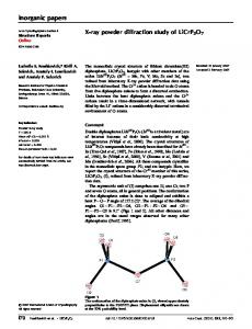
N. CHENEAU-SPATH, R. Y. FILLIT AND J. H. DRIVER The Siemens rotating-anode X-ray source allows measurement times of a few ms with a good signal/noise ratio. The collimator system is composed of a Soller slit and two cross slits and the detector combines a rear monochromator with a scintillator detector. The rotational movements of the sample are computer controlled via step motors that allow a very high rate of rotation (360 ° s-~). The angular increment used is 0.01125 ° and the total data-acquisition time (on a Nucleus 2000 board) is about 20 min. The interactive software has been modified to include the following features: (i) a systematic search, when the first (hkl) pole is detected, for the other {hkl} poles using the known {hkl} multiplicity and the crystal structure; (ii) a special coding technique that reduces the required memory space to a few kbytes instead of more than 10 Mbytes; (iii) a threshold treatment of the diffraction intensity data to eliminate X-ray fluorescence effects when K(~ radiation is used; (iv) a treatment to present the results as standard pole figures with intensity levels corrected for defocusing effects; (v) a second threshold treatment, developed to quantify the matrix/twin volume fraction ratios by measuring the relative integrated intensities. The integrated intensity diffracted by a given matrix pole is compared with that of the corresponding pole of the twinned material; this requires suitable defocusing corrections as a function of the inclined sample angle ~p. As a first approximation, attenuation effects due to the interaction of the diffracted intensities of matrix and twins are ignored since this requires an accurate knowledge of both population distributions. The system can detect peaks of width less than 1 0 - 2 o and is therefore perfectly suited to the analysis of largegrained samples for which the diffraction diagrams of all grains are collected simultaneously. Fig. 1 shows an TD
RD
981
example of the pole figure of a magnesium single crystal after directional solidification. It can also be used for deformed single crystals, which exhibit wider diffraction peaks, by simply increasing the angular increment and the data integration time: this flexibility means the equipment has a very wide range of applications. For the present study of twinned hexagonal crystals, Cu Kc~ radiation has been used in order to have as large a penetration depth as possible (,,~2 lam for titanium and ,-~ 15 gm for magnesium). The { 1010 }, {0002 } and {1120} poles are analysed since they are well separated and diffract strongly. 2.2. Back-scattered Kikuchi diffraction (BKD) The basic principles of BKD have been known for a long time but have only recently been applied to microtexture determination in a standard scanning electron microscope (SEM) (Venables & Harland, 1973; Dingley, 1981). The method consists of directing a stationary electron beam on the surface of a strongly tilted sample. The beam undergoes localized multiple reflections generating the equivalent of an internal divergent point source. Each family of atomic planes inclined at the Bragg angle diffracts into a wide open cone, which, when intersected by a plane, gives rise to two flat hyperbolae, i.e. practically straight lines. The entire set of diffracting planes creates a BKD pattern. In practice, a SINTEF BKD system has been installed in a JEOL 6400 SEM. The BKD diagram is formed on a fluorescent phosphor screen and is transmitted to a video monitor via a charge-coupled-device camera. An image processor (Hamamatsu Argus 10 C 2400) subtracts the background noise and numerically cleans the image. The current software determines the crystal orientation by comparing angles measured between three or more Kikuchi bands with known interplanar angles for a given crystal structure (Schmidt & Olesen, 1989). The BKD technique has the following typical characteristics: total solid angle 60°; angular resolution 2°; spatial resolution 0.2 to 1 lam (Dingley & Randle, 1992). The technique is therefore particularly suited to orientation determination in small grains and in twins of dimensions _>0.5 l.tm. Mechanical twinning essentially breaks up a grain into smaller (lenticular) grains of different orientations, related to those of the original matrix by well known crystallographic relationships. 2.3. Plastic deformation and crystallographic analysis
(10/1) Fig. I. High-resolution (10|1) X-ray pole figure of an as-solidified magnesium crystal (135, 1, -- 15).
For the development of several twinning systems in each sample up to large plastic strains, the crystals were deformed in plane strain 'channel die' compression. The single crystals of titanium were obtained from a commercially pure T40 grade by thermal cycling around the (~/f3 transition temperature followed by slow cooling. The magnesium crystals were grown by controlled
982
T W I N D E T E R M I N A T I O N IN H E X A G O N A L C R Y S T A L S
Table 1. Initial co, stal orientations Miller-Bravais indices Sample A B C D
(Ti) (Ti) (Mg) (Mg)
Euler angles (o) II 170 90 73
82 66 I 70
53 80 -15 54
Xi = R D
X2 = T D
11 4
I--7
2
4
3
T
2
1--3
13
~
2
g
TO
18
35
15 13
4 9
0 25
II 14
4 I1
15 3
0 4
solidification of 99.9%-purity magnesium in a horizontal mould; they were then cut to the sample dimensions of 8x6x llmm. From the entire set of orientations examined (Cheneau-Sp~ith, 1994), the typical behaviour of two titanium crystals (A and B) and two magnesium crystals (C and D), of orientations given in Table 1, is described here. The crystals were deformed at room temperature in plane strain compression using Teflon lubrication, which enables surface relief effects due to slip and twinning to be visible on the previously electropolished surfaces. The 'channel die' system described by Orlans-Joliet, Driver & Montheillet (1990) was used to produce a deformation mode similar that of rolling the {hkl} plane (of normal X3) in the [uvw] (Xi) direction. Absolute logarithmic strains of 0.1 to 0.7 were applied, in many cases up to the appearance of cracking. In the case of magnesium, this occurred at strains of 0.1 to 0.3 as a consequence of the limited number of slip systems available in magnesium at room temperature. The twinning systems activated in these crystals were those that have been most frequently observed in titanium and magnesium: in addition to the {1072} twins common to all hexagonal-close-packed metals, titanium twins on {1121} and {117.2} planes (Rosi, Dub6 & Alexander, 1953; Philippe, Esling & Hocheid, 1988), and magnesium on { 1011 } and { 10i3} planes (ReedHill, 1960). Activation of a twinning system leads to a reorientation of the twin compared with the matrix; any vector d in the matrix is transformed to a direction d' according to the standard formula d' = T • d,
X3 = N D m
19
(1)
where T is the transformation matrix for a particular twinning system. The transformation matrices* for the above standard twinning systems are given by CheneauSp~ith (1994). In practice, during twinning the normal direction n of the matrix crystal creates, for each twinning system, a corresponding direction n'. This can be compared with the experimentally observed twin and matrix orientations and the twin traces to uniquely determine the twinning system. * The detailed transformation matrices for standard twinning systems in titanium and magnesium have been deposited with the IUCr (Reference: VI0027). Copies may be obtained from The Managing Editor, International Union of Crystallography, 5 Abbey Square, Chester CHI 2HU, England.
6 9 0 12
9 2 0 17
15 II 0 29
2 5 I 10
The BKD method has the immediate advantage of providing images and orientations of the twinning systems in any area greater than l lam 2, whereas the Xray method is applied to larger areas (of the order of mm 2) and also requires a parallel trace analysis for unambiguous identification, e.g. by optical microscopy.
3. Experimental results 3.1. Titanium c~stals
For orientation A, deformed to a strain of 0.5, the traces of the apparent twinning systems visible on the compression surface are shown in Fig. 2. Table 2 summarizes the measured angles of the twin traces, their possible twinning planes and the BKD orientation analyses. The latter in fact reveal that three different twinning systems are active • (0i12), (i012) and (01 i2). Fig. 3 shows the corresponding (0001) and (10i0) pole figures obtained by the high-resolution X-ray scan on the same crystal surface deformed to s = 0.5. Comparison of the pole figures of Figs. 2 and 3 shows that they are virtually identical. The X-ray method is therefore clearly capable of picking out the narrow twin and matrix poles after plastic deformation. As shown by Cheneau-Sp~ith & Driver (1994), orientation B of the titanium crystals deforms extensively by twinning. The same BKD analysis as above (Fig. 4a) unequivocally demonstrates the following twinning systems: (i) predominant twinning on (1121) (this type of twin completely traverses the entire crystal); (ii) minor twinning on (ii22), (i012), (10i2) and (01 i2) planes. It is interesting to note that, according to the active twinning systems, the standard (0001), (1070) and (1120) pole figures can exhibit singular features. Thus, (10i2) twins are associated with an invariant (117.0) pole of the twin and the matrix while the e axis is interchanged with one of the (1070) poles. Similarly, during twinning on the { 1 I?.1 } and { 117_2} planes, one of the {1070} poles remains invariant. The invariance of the {10i0} and {117.0} poles can be explained by the form of the transformation matrices that give the coordinates of a matrix direction in the crystal coordinates of the twin. The corresponding (0001) and { 1120} pole figures obtained by the X-ray method (Fig. 4b) are similar to the
N. C H E N E A U - S P A T H ,
983
R. Y. F I L L I T A N D J. H. D R I V E R
Table 2. Twin trace and BKD analysis of titanium sample A Angle between twin plane and RD Twin trace SEM (°)
Possible twinning systems Trace analysis
1
31
(10]'2)
(0i12)
(1]-02)
2 3
166 159
(01T2) (01]2)
(T102) (T102)
(]012) (TO 12)
BKD analysis (TO 12) (]012) (10]-2)
(0112) (OT12) (01]2)
TD
t2
f
J
J
s
t3
RD
..
(0001 )
TD
TD
"~RD
RD
~ t3 4
\,
(10-10) Fig. 2. BKD twinning analysis of the compression surface of the titanium crystal A at ~ = 0.5; tl = (0112), t2 = (i012), t3 = (01i2). TD
TD
%.:
t2 RD
RD
t~
I
",, (OOOl)
/
/
I /"V ",, I .,,.."/ (lo]-o)
Fig. 3. X-ray (0001) and (10i0) pole figures taken from the compression face of the titanium crystal A at e = 0.5; tl, t2 and t3 as in Fig. 2.
984
T W I N D E T E R M I N A T I O N IN H E X A G O N A L C R Y S T A L S
Table 3. Identified twinning systems in titanium sample B Twin trace
Angle (o)
tl t2 t3 t4 t5 t6
3 140 25 155 160 146
pole figure but not in the local area analysed by BKD in Fig. 4(a). System t2 was detected by BKD in other areas. The BKD analysis does, however enable one to separate twinning systems with similar pole positions, for example the t3 and t4 poles in Fig. 4(b) regroup both the (i012) and the (10i2) poles.
Twinning system (1 121) (2112) (1 oT2) (_1012) (1 122) (01T2)
3.2. Magnesium crystals
BKD figures, although very diffuse after a strain of 0.7. This spread arises from the orientation distribution of the matrix. Table 3 summarizes the six twinning systems identified by BKD and X-ray diffraction in this sample. Note that, as a consequence of the heterogeneous nature of twinning, system t2 appears quite strongly in the X-ray
In the case of the deformed magnesium crystals, the BKD method proved difficult to apply because of the rapid oxidation of the crystal surfaces in air. This surface oxidation, together with the low atomic number of magnesium, severely ;mpeded the obtaining of good
......
TD
RD TD
f..I"" .~"
(ooo i ) (a) TD
TD
RD
i
\
\
(oool)
/ RD
-
/
/
(1120) (b)
Fig. 4. Twinning systems on the compression face of the titanium crystal B at e = 0.7. (a) BKD analysis. (b) X-ray (0001) and (11)-0) pole figures. The twinning systems tl to t6 are identified in Table 3.
985
N. C H E N E A U - S P A T H , R. Y. F I L L I T A N D J. H. D R I V E R
back-scattered Kikuchi patterns. Hence, only the highresolution X-ray pole-figure results are presented lbr the magnesium crystals. Note also that, in the case of magnesium, the invariance properties of the (10/0) poles during {I 1~_1} and { 1122J twinning are no longer respected. However, the (11~.0) matrix and twin poles are invariant for (1071) and (10]3) twinning. Crystal C, characterized by the c axis close to the compression direction, ND, is particularly hard to deform plastically; deformation essentially occurs by twinning before cracking intervenes, along the twin-matrix interfaces, at relatively low strains (Cm~,x ~ 0.1). Fig. 5 shows the resulting X-ray { 10].0} poles obtained on the compression face. The twinning systems can easily be identified as { 10]'2} twins situated at 60 ° to each other as a consequence of the sixfold symmetry of this particular orientation. The final orientation, crystal D, undergoes a large lattice rotation during deformation as a result of extensive slip on the basal plane. This leads to rather elongated poles, particularly the (0001) pole (Fig. 6). In fact, the (0001) and (10]'0) X-ray pole figures reveal three types of twins, denoted (~, /3 and '7, in addition to the matrix orientation. (]'012) twinning, corresponding to the c~ poles, is easily identifiable; however, the fl and "7 poles cannot be immediately identified with common twinning systems in magnesium. Nevertheless, analysis of the (1070) and (0001) pole figures reveals the invariance of the (11,20) poles and the permutation of the (10]'0) and (0001) poles of (~ with/~ and "7, respectively. This is consistent with secondary twinning inside the primary (]'012) twins. There is also evidence of double twinning in the micrographs of the compression and longitudinal faces (Fig. 7). They can be identified as secondary (1072) and (1i02) twins. This double twinning phenomenon occurs only rarely in titanium but is quite frequent in magnesium. It is clearly detected by the high-resolution X-ray method when the volume fraction
of the double-twinned material is sufficiently high. The accuracy of the X-ray volume fraction measurements is about 1% for twins of dimension greater or equal to 1 gin. The twinned volume fraction is generally difficult and laborious to evaluate by conventional techniques such as optical microscopy. We have used the high-resolution X-ray pole-figure intensities to determine these values in the above samples. The results summarized in Table 4 show reasonable agreement with those obtained by optical metallography.
4. C o n c l u d i n g
remarks
Two quite different methods have been used to determine the twinning systems in deformed hexagonal single crystals. The BKD microdiffraction system in a standard scanning electron microscope provides local orientation measurements down to ~ 1 gm together with direct imaging of the twins. The new high-resolution X-ray pole-figure method is particularly adapted to highly deformed single crystals. Both methods give the same twin
TD
RD
(0001)
TD TD
~~:"~'~.~i.:~"
~
RD
R
( oTo} Fig. 5. (1010) high-resolution X-ray pole figure of the magnesium crystal C at ~ = 0.1.
Fig. 6. (0001) and (lO]O) X-ray pole figures of the magnesium crystal D at ~ -- 0.3. See text for the identification of the twinning systems o, $ and ~.
986
TWIN DETERMINATION IN H E X A G O N A L CRYSTALS
Table 4. Experimental twinned volume fractions as measured by the integrated X-ray peak intensities and the area fractions in optical microscopy
analysis when applied to deformed titanium crystals. Their relative merits are summarized in further detail below. I. Advantages of the BKD system
Twinned volume fraction (%) Sample
X-ray method
Optical microscopy
A B C D
8.3 38 11 26
-,~5 40-50 --~15 30-35
(i) good angular separation (1 or 2 °) between twins of very similar orientation; (ii) accurate local orientation information up to quite large plastic strains (0.7 in titanium); (iii) easy extension to the characterization of twins in the grains of deformed polycrystals.
RD Double Twinning
( 012) TD~ (a)
~.~"
...... ;::' ;~
~:,
~ ~,~, :~,~~~,!k~l(]-OleG~ v 2) Twin
(0001) Slip
/
(]-012) Twin
~:
Double Twinning • .L! OJ2)
Double Twinning (1]-02) ~i
/
,
-
RD
\(0001) slip
Fig. 7. Optical micrograph of the magnesium crystal D deformed to s = 0.09 showing double twinning. (a) Compression face. (b) Long transverse face.
N. CHENEAU-SP,~TH, R. Y. FILLIT AND J. H. DRIVER II. Useful features o f the high-resolution X-ray polefigure method (i) rapid global texture measurements; (ii) quantitative analysis of the relative volume fractions of twins and matrix; (iii) detection of very fine twins of thickness less than 1 lam, as for example in double twinning; (iv) no requirement for particular surface preparation; (v) use possible on specimens deformed to very high strains. The authors express their gratitude to the R h 6 n e - A l p e s Regional Authority for partly financing the SEM BKD system and the rotating-anode X-ray source.
References
BRIZARD, C., ROLLAND,G. & LAUGIER,F. (1993). J. Appl. Crvst. 26, 570-573. BUNGE, H. J. & ESIJNG, C. (1982). Quantitative Texture Analysis. Oberursel: Deutsche Geseilschafi ftir Metallkunde. CHENEAU-SPATH, N. (1994). Thesis. Ecole des Mines de SaintEtienne, France. To be published.
987
CHENEAU-SPATH, N. & DRIVER, J. H. (1994). Proc. Conf. ICOTOMIO, Mater. Sci. Forum, 157-162, Part I, pp. 639-644. COULOMB, P. (1972). Les Textures dans les Mdtaux de Rdseau Cubique. Paris: Dunod. DINGLEY, D. J. (1981). Scanning Electron Microsc. 4, 273-286. DINGI,EY, D. J. & RANDLE, V. (1992). J. Mater. Sci. 27, 4545-4566. FILLIT, R. Y., PERRY, A. J., DODEI.ET, J. P., PERRIER, G. & PHILIPPE, K. (1991). Nondestructive Characterization of Materials IV, pp. 1-8. New York: Plenum. MINONISHI, Y., MOROZUMI, S. & YOSHINAGA, H. (1985). Scr. Metall. 19, 1241-1245. ORLANS-JOIAET, B., DRIVER, J. H. & MONTHEIIJ,ET, F. (1990). Acta Metall. Mater. 38, 581-594. PHILIPPE, M.-J., ESLING, C. & HOCHEID, B. (1988). Textures Microstruct. 7, 265-301. REED-HILL, R. E. (1960). Trans. Metall. Soc. AIME, 218, 554-558. ROSI, F. D., DUBI~,C. A. & AI.EXANDER, B. H. (1953). J. Met. pp. 257-265. SCHMIDT, N. H. & OLESEN, N. O. (1989). Can. Mineral. 27, 15-22. SCHULZ, L. G. (1949). J. Appl. Phys. 20, 1030-1033. SCHUSTER, M. (1993). Private communication. SLUIS, P. VANDER (1993). Mater. Sci. Forum, 133-136, 237-242. VENABLES, J. A. & HARLAND, C. J. (1973). Philos. Mag. 27, 1193-1200.