Improvement of Metropolitan Wireless Networking Using Wireless Optical Mesh Networks Mohammad Ghaleb Ali, Wail Mardin1, Akbar Ghaffar Pour Rahbar, Yaser Khamayseh
Improvement of Metropolitan Wireless Networking Using Wireless Optical Mesh Networks Mohammad Ghaleb Ali*1, Wail Mardini*1, Akbar Ghaffar Pour Rahbar*2, Yaser Khamayseh*1 *1 Computer Science Department, Faculty of Computer and Information Technology, Jordan University of Science and Technology, Irbid 22110 Jordan *2, Computer Networks Research Lab, Department of Electrical Engineering, Sahand University of Technology, Tabriz, Iran
[email protected],
[email protected],
[email protected],
[email protected] doi: 10.4156/jdcta.vol3.issue3.7
Abstract
Keywords
Many wireless networking systems were established to manipulate metropolitan networks in order to provide internet, voice, data, video and TV services in large cities. Two major systems were used for such services; Local Multipoint Distribution Service (LMDS) and Multi-channel Multipoint Distribution Service (MMDS). Both of these systems are fixed broadband access networks and both have problems in the cost, speed, coverage area and last-mile bottleneck, especially when the network size is increased. Deploying a new technology of a Wireless Optical Mesh network (WOMN) which uses wireless optical communications between nodes can overcome these problems and can provide more bandwidth, an interference-free network, a frequency-free network, and more effective applications that require a real time responding like video surveillance. We investigate the WOMN against LMDS and MMDS to show that WOMN is better than both LMDS and MMDS in commercial, geographical coverage, and real time applicability. We will also investigate the challenges to deploy the new technique for local and metropolitan networks between different city buildings. Furthermore, we will show that we can have a better performance by including microwave weather detection mechanism through the estimation of the fog and rain presence under several different conditions. In addition, combining the Free Space Optic (FSO) technology with the 60GHz radio waves can increase the WOMN link availability, thus providing an alternative communication way and increasing the distance between wireless optical devices. This strategy can avoid the effect of fog and snow on wireless signal since they do not have effect on the propagation of 60GHz radio waves. The WOMN link can be engineered by adjusting antenna size, choosing a high-power option, and changing the microwave frequency.
Wireless Optical, Mesh Networks, LMDS, Free space optics.
1. Introduction The Multi-channel Multipoint Distribution Service (MMDS) and Local Multipoint Distribution Service (LMDS) were introduced to provide communication by wireless networking among large cities. Some applications that were used in these networks are: local television, Internet, video to provide broadband services to residential buildings, and small businesses, where Digital Subscriber Line (DSL) or cables are not available [1]. These systems can solve the problem of the small data transfer among subscribers. However, they dramatically increase delay when customers need a huge amount of data like hundreds of cameras for real time surveillance. The MMDS and LMDS will have some problems to deal with this huge amount of data in a real life. A newer technique was appeared to overcome this bottleneck problem; called Wireless Optical Mesh Network (WOMN) which uses the new idea of using a free direct laser instead of microwave frequency that needs costly base stations. However, the WOMN network can be easily extended from a local area network to a metropolitan area network [2].
1.1 Related Work The Institute of Electrical and Electronic Engineers (IEEE) makes 802.16 as a standard for Worldwide Interoperability for Microwave Access (Wi-Max). WiMax provides interoperable broadband wireless connectivity to fixed and portable users [3, 4]. Wi-Max was developed from MMDS and LMDS systems; they are fixed metropolitan wireless networks. They were appeared to serve internet, data, voice, and TV to
60
International Journal of Digital Content Technology and its Applications Volume 3, Number 3, September 2009 A wireless metropolitan network available in the market does not produce a real solution to the last-mile bottleneck problem, especially when the number of subscribers is increasing and a huge data is being transmitted. This problem may slow down the system quickly. By increasing the need for real time multimedia applications, interactive video, interactive games, software download, work from home, video conferencing, and streaming video file transfer, this paper investigates the WOMN model which was presented recently to solve these problems [2]. This system also presents an idea to avoid the bad weather problems such as rainfall and to make an interactive system with weather conditions.
companies and large residential complexes. Both of these systems have a number of advantages and disadvantages. Before discussing our system, we discuss some related works [1, 4]. MMDS and LMDS are both point-to-multipoint microwave systems that are usually licensed on a trading area. In general, large single cell architecture is favored for MMDS. Deploying a multi-cell system is generally not efficient because MMDS frequency is near 2.5 GHz which requires either large antennas or small antennas with very broad beams that causes multi-path fading, where the communication signal travels from transmitter toward a receiver along many and different paths simultaneously. This may decrease the received signal strength, because of the reflection of the signal associated with broad beams [2]. In the deployment of single cell MMDS, the available bandwidth is limited to the frequency band license, which is equal to or less than 200 MHz in total [1]. LMDS operates at a licensed frequency as well as MMDS. It also travels in a line-of-sight (LOS) with free space attenuation that is increased by atmospheric absorption due to the moisture and the pollution. Using high frequency waves such as 30 GHz in LMDS would cause a problem in the system, where its signals will attenuate in rainfall weather. The high frequency waves allow companies to construct small antennas with an excellent direction that is one of the key factors to reduce multi-path fading [5]. LMDS system has been designed as a two-way communication system incorporating either frame relay or Asynchronous Transfer Mode (ATM) switching technology. The drawback of this system is the cost of the complex switching technology and the cost of the power amplifier for return links [5, 6]. The study in [7] describes and uses some simulation models to compare the performance of four different configurations of the LMDS system.
1.4 Methodology and Justification We shall investigate, design, and prove that using wireless optical in a mesh topology in metropolitan areas 1) could improve the performance of the metropolitan networks; 2) could increase network bandwidth; and 3) could decrease the cost of the metropolitan network. We compare the two metropolitan models, LMDS and WOMN using simulation. We use the QualNet software [28] to simulate and prove our work. This software is visual software that helps design and simulates a real metropolitan network with different parameters and environments. We compare different characteristics between the two models such as total bytes received in a certain time, throughput, and end to end delay.
1.5 Assumptions The assumption is to use a Free Space Optics (FSO) in a mesh topology instead of using microwave frequencies that are used in LMDS and MMDS systems. The FSO devices connect the whole city with each other using wireless optical devices that are called TereScopes. Microwave signals are affected by the rainfall considerably when the effect of fog is very small. FSO is not affected terribly by rainfall like other systems. However, it is affected by fog. The attenuation that occurs in fogy weather in FSO is similar to the attenuation occurs in microwave systems due to rainfall [1]. Therefore, this system can overcome dense fog problems by decreasing the distance between wireless optical devices and providing microwave frequency.
1.2 Problem Statement Using wireless networking for a large area has many obstacles such as frequency licensing, cost of base stations, last-mile bottleneck, security, and relatively small bandwidth. This means that if a system uses hundreds of cameras for video surveillance and video conferencing; the system will dramatically fall down because of the competition on using the small bandwidth. This paper studies possible solutions to overcome this problem.
1.6 Outlines of the Paper
1.3 Motivations and Main Contribution
The paper is divided into six sections. The first section includes introduction, related works, problem
61
Improvement of Metropolitan Wireless Networking Using Wireless Optical Mesh Networks Mohammad Ghaleb Ali, Wail Mardin1, Akbar Ghaffar Pour Rahbar, Yaser Khamayseh statement, motivation, contribution, methodology, justification, assumption, and outlines of the paper. Section 2 provides an overview of LMDS and MMDS systems, the characteristics of both systems, and the structure of the LMDS system. Section 3 reviews the FSO, its characteristics, and the problems of using the wireless optical, and its solution. Section 4 discusses the advantages of WOMN over LMDS, and possible solutions for some problems of the WOMN system. Section 5 shows how to use the QualNet software to build the WOMN and LMDS network models, describes the simulation experiments in detail, and presents the results that were obtained from our experiments. Section 6 provides a summary of the paper and a conclusion of the simulation results.
than 150 channels. This system operates in the 2GHz to 3GHz band, therefore it can cover a large area close to 55 kilometers and network capacity will be shared among all users receiving services from a given base station. Data throughput ranges will be between 128Kbps to 10Mbps. Its throughput and long distance make MMDS appropriate for TV channels. However, if environmental conditions are not favorable, the performance may go down [1, 14]. Before deploying MMDS services, the licensing process must be completed. Since the MMDS equipments are expensive, there is still a challenge to make a desired low price system. The MMDS has a problem with maintaining LOS, which is required between base stations and subscribers. Some obstructions such as trees, precipitation, and multi-path fading can cause additional problems. To overcome these obstructions, customers need many transmitters and antennas [14]. To overcome a LOS deployment of MMDS, the Orthogonal Frequency Division Multiplexing (OFDM) technique can improve capacity and performance of wireless systems. OFDM enables more data to be transmitted at higher speed, and the signal will be strong enough for transmission through obstacles. Using OFDM, the transmitted data is spread over a set of individual frequencies that extends for a very broad range and therefore multi-path fading and interference can be avoided, at the expense of increasing network budget [1, 4].
2. The MMDS and LMDS systems There is an increasing interest in the applications of wireless technologies in Metropolitan Area Networks (MANs), in particular with the wireless local loop deployments, delivery of internet access, and highspeed video transmissions. There are two techniques for supplying broadband access via point-to-point microwave: Multi-channel Multipoint Distribution Service (MMDS) and Local Multipoint Distribution Service (LMDS). The following discusses each of these techniques in detail.
2.1 The MMDS System
2.2 The LMDS System
The first licensed usage of MMDS was in the 1970s, where it was licensed to broadcast one-way 6MHz television channels. However, in 1998, the MMDS offered two-way services for the Internet by upgrading to bidirectional systems [6]. Figure 2.1 illustrates the MMDS deployment, which consists of a base station in a high mountain that transmits data to the subscribers with Line-Of-Sight (LOS) between base station and the subscribers.
LMDS is a system used for broadband microwave wireless point-to-multipoint communications. It is based on a direct access from a local antenna to homes and business within a LOS. It usually operates at frequencies above 10 GHz that can be used to provide digital two-way voice, data, Internet, and video services. As a result of the propagation characteristics of signals in this frequency range, LMDS systems use cellular-like network architecture, and therefore, the services provided by LMDS are fixed not mobile. The average distance between LMDS transmitters is approximately one mile apart [6, 15]. LMDS network is used by residential and commercial subscribers to deliver broadband services in a point-to-point or point-to-multipoint configuration. LMDS stands for [6]: L (local): the propagation of the waves is limited in a local area. M (multipoint): the signals broadcast by a base station are point to multipoint. The wireless return path,
Figure 1: The MMDS [1] Since MMDS used nowadays is a digital system not analog, it provides great capacity and enables more
62
International Journal of Digital Content Technology and its Applications Volume 3, Number 3, September 2009 from the subscriber to the base station, is point to point. D (distribution): distribution of voice, data, and Internet traffic simultaneously. S (service): services are provided to customers by a service provider.
each system, it can serve 5,000 to 10,000 homes. The applications of LMDS are wireless local loop, highquality telephony, Internet access, two-way video, security, and energy management systems. The first market for this service is the business world, rather than home consumers [6, 17]. LMDS downstream rates are in the range of 51Mbps to 155Mbps and a return link of 1.5Mbps. It involves LOS microwave [1]. Figure 3 shows that the base station node communicates with residential, commercial, industrial, and institutional subscribers. LMDS supports very-high bandwidth. The key concern with LMDS is that it operates in a very high portion of the microwave frequency band, making it easily obstructed. LMDS suffers from distortions when environmental or weather conditions are bad [1, 17].
Data modulation for LMDS varies between Time Division Multiple Access (TDMA), Frequency Division Multiple Access (FDMA), and Code Division Multiple Access (CDMA) [6]. Upstream direction from subscribers to a base station usually uses TDMA, FDMA, or CDMA. However, CDMA is not considered. In the downstream direction from the base station to subscribers, TDMA is usually used [7]. The LMDS technology consists of four primary components [6]: 1. 2. 3. 4.
3. FSO and WOMN Systems
Network Operations Centered (NOC). Fiber-based infrastructure. Base Station Unit (BSU). Customer Premise Equipment (CPE).
Free Space Optics (FSO) is a wireless broadband technology that uses lasers or infrared light pulses [14], started in 1880 when Alexander Graham Bell transmitted his voice as a telephone signal through about 600 feet of free space (air) using a beam of light as the carrier. He named his experimental device the photophone. In 1999, the multi-channel optical wireless transmission system appeared [16]. This section discusses FSO and Wireless Optical Mesh Network (WOMN).
The NOC consists of Network Management System (NMS) equipment that monitors the performance of the network and manages large regions of the customer network. Multiple NOCs can be interconnected with each other [6]. The fiber-based infrastructure consists of Synchronous Optical Network (SONET) optical carrier, central-office equipment, ATM, and interconnections with the Internet and Public Switched Telephone Networks (PSTNs) [6, 17]. The BSU equipment consists of network interfaces for fiber termination, modulation and demodulation functions, and microwave transmission and reception units. However, the CPE includes digital equipments that provide modulation, demodulation, control and the requisite microwave [6, 17]. Figure 2 illustrates the LMDS system with two base stations. Each base station forms a center of the cell and transmits data to the subscribers inside the cell, and each cell has its own frequency to avoid interference between two cells. LMDS is terrestrial LOS microwave; it operates in the 10GHz to 45GHz range, depending on the country deploying it. A large frequency of 13GHz operates in smaller micro cells of 1 to 5 kilometers [1]. Within
Figure 2: The LMDS System, Point-toMultipoint Wireless MAN [18]
3.1 Free Space Optics FSO is a last-mile technology that accommodates intensive bandwidth applications such as voice, video, data, and Internet. It is an outdoor wireless product category that provides the speed of fiber, with the flexibility of wireless [18]. FSO can be used in short range applications that reach up to approximately 2 kilometers and can be used to connect buildings or establish a connection to backbone networks [14]. FSO uses invisible beams of light to provide optical bandwidth connections with LOS technology. It is capable of sending up to 1.25Gbps of data, voice, and video communications simultaneously through the air enabling fiber-optic connectivity without requiring
63
Figure 3: Base station communicates with residential and commercial subscribers in LMDS [1]
Improvement of Metropolitan Wireless Networking Using Wireless Optical Mesh Networks Mohammad Ghaleb Ali, Wail Mardin1, Akbar Ghaffar Pour Rahbar, Yaser Khamayseh physical fiber-optic cable [18]. It enables optical communications at the speed of light. The optical connectivity does not require expensive fiber-optic cable or securing spectrum licenses for Radio Frequency (RF) solutions because these frequencies do not propagate everywhere in the space and they are not registered in any federation agency for radio licenses. The use of light is a simple concept similar to optical transmissions using fiber-optic cables; the only difference is the transmission medium. Light travels through air faster than it does through glass. Optical wireless uses low-powered infrared lasers. Figure 4 illustrates a typical connection using wireless optical between Point Of Presence (POP) and other residential, commercial, industrial, and institutional subscribers [1, 14, 18]. There are two categories for Optical Wireless [1]:
communication link by reducing the range of the link or by deploying redundant wired or microwave infrastructure. Another problem with FSO is that buildings sway a little bit, so auto tracking mechanisms are required with FSO equipments to ensure that the beams stay highly focused on one another [22]. Figure 5 show that when the skyscrapers sway, the beam will miss its target unless there is an auto tracking mechanisms that the beams stay highly focused between the skyscrapers.
1. Point-to-point products, which provide high-speed connection between two buildings. 2. Multiple high-speed connections through the air that operate over much shorter distances. It can exist in either a point-to-multipoint or a meshed architecture.
Figure 5: Auto-tracking mechanisms ensure that the beams stay highly focused between building [22] Another problem is the flying of birds across the beam, which can cause distortion. To obtain better reliability, mesh architectures should be deployed in areas where the number of flying objects is small. However, it has been reported that birds can in fact see the infrared section of the spectrum and will typically avoid the beam [18]. It is still possible that they fly through the beam, and this is likely to disrupt communication. However, if a reliable protocol such as TCP/IP has been implemented, any lost packets will be retransmitted, and this can overcome all lost packets [3].
Figure 4: Small area connected by FSO [1] The point-to-point architectures operate over a range of 2 to 4 kilometers. The point-to-multipoint architectures operate over a range of 1 to 2 kilometers and both architectures offer throughput of 155Mbps to 10Gbps. However, the meshed architectures operate over shorter distances from 200 to 450 meters, and offer throughput of around 622Mbps [1, 18].
3.3 Wireless Optical Mesh Network (WOMN) This is a new network modeling technique introduced during the last few years. It is a point-topoint communication system. Nodes communicate with each other by laser in Terahertz frequency. It is used to increase the distance for a network and provides a huge bandwidth that can be used in a video surveillance system for a hundreds of cameras and smart doors simultaneously with fiber-like capacity [2, 9, 23]. Mesh topology is not limited to a circular or any other geometric structure. The size of the area covered by WOMN can almost be unlimited. The topology consists of [2]:
3.2 The Problems of Using the Wireless Optical and Solutions The key problem with FSO is weather, especially fog. By going up in the electromagnetic spectrum, which means the increase of the data rate transmission speed, the waveforms become smaller, so droplets of moisture can cause interference [19, 20]. It is possible to reduce the impact of bad weather on the
64
International Journal of Digital Content Technology and its Applications Volume 3, Number 3, September 2009 o Central backbone Point Of Presence (POP). o Fast Ethernet wireless optical link. o Laser Equipment like TereScope to transport data between nodes. o Optical Access Layer 3 switch device.
link active. This is usually measured in dB (decibels), where dB = 10 × log (Power / Min. power) [24]. The description of the formula is: o dB: measures of loss or gain of the power of a wave, usually negative numbers representing loss of power as the wave travels, and positive values represent a gain in power if the signal is amplified [3]. o Min. power: the minimum power the receiver must receive to keep the link active. o Power: the amount of power that should be sent to keep the link active in different weather conditions.
Each node (e.g., a building consisting a wireless network) communicates with other nodes by a TereScope that can transmit voice, data, internet, and video by laser with Terahertz frequency. Each mesh node is equipped with an optical access switch device and the node on a building itself provides an additional Ethernet stream. Figure 6 illustrates part of the model, in which each building has its own local network connected with a router, switch, or hub. A TereScope connected to a router can focus its beam to another TereScope in another building that has its own network. Each building could contain multiple TereScopes that direct its beam to a different building which can make a mesh topology.
We can obtain larger link range through atmosphere by having higher output power on the transmitter side of the laser equipment and it can handle more difficult weather conditions like dense fog. A larger receiver diameter is better to collect more of incident light [24]. Figure 7 illustrates how the beam diverges when transmitted from the transmitter to the receiver, and the wasted light.
Figure 7: Beam Divergence [24] Link margin of a particular FSO is affected by two factors related to each other, the distance between terminals and the weather condition. A two kilometer distance link will have lower margin than 1 kilometer link because of the greater atmospheric attenuation over longer range. Therefore, before establishing FSO equipments, customers should determine the distance and the worst case weather conditions could happen in their area [18]. LMDS can be penetrated with new technologies because the frequency can be discovered and an attacker can easily spy on the wireless network. Note many RF systems, like cellular phones, police radios, and wireless LANs intentionally radiate signals in all directions making the signal accessible to anyone with a receiver. On the other hand, WOMN can be a secure network because it has a low probability of intercepting the beam. Since the radiating is point to point, transmission in a narrow beam width minimizes the interception of the beam. If the beam is intercepted, the connection between transmitter and receiver will be disconnected [18].
Figure 6: Part of the WOMN System [2] The WOMN has no restrictions to any geometrical shape; consequently, maximum geographical coverage can be achieved at a minimum cost. The availability of high bandwidth on wireless optical links and the mesh architecture, enable multiple paths from the backbone POP to any subscriber. This enables connectivity to the subscribers even in cases when parts of the access network fail [2]. To connect two computers as an example in two different buildings, the first user may be connected to a wireless network while the other user in a different building may be connected to an Ethernet network. Then, the two buildings are connected to each other with wireless optical equipments (not fiber optics). Each wireless optical equipment, connected to a switch or a router device uses the Open Shortest Path First (OSPF) routing protocol that routes packets on the shortest path to another user or internet service [2]. To obtain the benefits of the WOMN system, customers must increase the link margin between laser equipments, where the link margin is the amount of light received by a terminal over the link and its value of lights received above what is required to keep the
3.4 WOMN Combined with Other Systems
65
Improvement of Metropolitan Wireless Networking Using Wireless Optical Mesh Networks Mohammad Ghaleb Ali, Wail Mardin1, Akbar Ghaffar Pour Rahbar, Yaser Khamayseh WOMN can be combined with several different local networks to connect computers in a city with each other. The following discusses some examples of these combinations. It should be noted that those systems would be used as backup systems for WOMN. Backup systems can carry only high priority traffic, because the bandwidth limitations for those backups are small in comparison with WOMN.
weather. Combining the wireless optical transceiver with unlicensed Wi-Fi radio solutions can make availability of five 9's up to 5 kilometers, where five 9's means that the link availability or percentage of time that a customer can expect a link to operate in a particular location is 99.999 % [27]. When wireless optical links go down due to a dense fog or snow event, the network notices the link failure and temporarily and automatically redirects traffic over the Wi-Fi microwave radio path. Once the environmental trouble finishes, the router shifts the traffic back to the high capacity of wireless optical link [13, 18].
3.4.1 WOMN with Microwave RF WOMN transceivers provide high-speed connectivity up to 1 Gbps speed over distances from 75 meters to 5 kilometers. For higher availability, we can combine wireless devices with an alternate path microwave RF solution [18, 27]. Figure 8 shows a sample use of Optical Link and RF architecture, in which the RF system operates when the optical link is disconnected because of dense fog. The unlicensed microwave RF frequencies can be used with WOMN, where there are two choices of the unlicensed RF: the 2.4GHz to 5.8 GHz bands and the 60 GHz band. The 2.4 GHz to 5.8 GHz bands have limited throughput and interference due to frequency saturation, while 60 GHz provides a higher bandwidth. However, the 60 GHz frequency suffers from oxygen absorption and rain fading, thus, decreasing deployments beyond 400-800 meters, depending on the rain region [24, 27].
WI-FI network
Figure 9: Combination of WI-FI and WOMN Figure 9 shows how a POP that can be connected to a campus, hospital, and neighborhood that use Wi-Fi spot, in which POP is connected with FSO link while the campus is connected with Wi-Fi wireless technology.
4. Improvements of using the WOMN System There is an increasing demand for secure networks and real time surveillance cameras in cities so that a large number of information could be collected from streets, hospitals, schools, universities, airports or any other place without being spied or penetrated by any one. This could not be done using microwave signals, where any one can penetrate to that system. So the idea of using a narrow beam in a point to point architecture that can carry large information with a large bandwidth is a demand for any government or organization [9]. This section previews advantages of WOMN over LMDS to show the real benefits of using WOMN in cities, and then justifying our improvement on WOMN for better applicability on different systems by using FSO technology with weather detections to detect the bad weather such as fog and with addition microwave frequency equipment to overcome the probability of stopping the laser beam between TereScopes when very dense fog occur.
Figure 8: Wireless link with microwave RF [18] 3.4.2
WOMN and Wireless Fidelity (Wi-Fi)
Wi-Fi is a wireless technology with data rate of 11 Mbps to 54 Mbps used in a short distance around 100m; this technology can be deployed and expanded dynamically. Combining two technologies such as WiFi and WOMN in a city can make a revolution in connecting customers with each other. Most technologies provide only a half-solution from the complete network perspective [9, 13]. The new wireless optical transceiver equipments are a combination of advanced receiver technology and high powered 1550nm lasers coupled with customer's laser devices. This higher transmission power could increase link distances and decrease the effects of bad
4.1 Advantages of the WOMN over LMDS
66
International Journal of Digital Content Technology and its Applications Volume 3, Number 3, September 2009 Using WOMN instead of LMDS in a city could have many commercial and technical advantages. The following are some of those advantages:
it is very secure. However, an LMDS base station transmits data every where, even the subscribers devices transmit data to base station in a cone shape [18, 25].
1. Free frequency license: WOMN employs FSO to transmit data, which uses large frequencies up to terahertz. These frequencies are sent in point to point architecture and do not need any license to use. 2. Low cost: LMDS is costly compared to WOMN. An LMDS cell requires a licensed frequency and a base station which costs between $500,000 and $1,000,000. However, WOMN does not require licensed frequency, base station, fiber optics, digging, and annual fees [18]. WOMN only requires few wireless optical devices and switch devices no more than $100,000 [2]. 3. Easy deployment: Basic mesh structure can be deployed within days. Service provisioning can begin immediately, and the connection to the wireless optical devices and switch devices could be established in hours since TereScopes are small and portable. However, the LMDS takes few months to deploy the base station. Sometimes it is impossible to put the base station in a desired location in the case of LMDS because it needs approval from the governments or environments authority [9]. 4. Better coverage area: LMDS consists of many overlapping circular cells, where each cell has it own base station. The cost to cover a large area will be high. While the WOMN architecture has no restrictions to any shape, and can extend to cover large area with minimum cost [18]. 5. Huge bandwidth: WOMN operates at the frequency range of Terahertz, enabling the network bandwidth to be up to 10Gbps [2], while the LMDS operates at the frequency range of Gigahertz of microwave links which has a limited bandwidth up to 1Gbps. Therefore, the total throughput of the WOMN can be upgraded to many Gbps, satisfying community bandwidth demands in today and future [9]. 6. Reliability: WOMN increases the connectivity to subscribers, which offers at least two paths into each building. Therefore, if parts of the network fail there will be an alternative path to all subscribers with sufficient bandwidth. While in LMDS, if the base station fails the communication of all subscribers in the cell will stop. 7. Secure systems: Since WOMN devices transmit data in a narrow invisible point to point, therefore,
4.2 The Problems and Improvements for WOMN System Since the WOMN uses FSO, it is affected by some environmental conditions. The availability of FSO depends on local atmospheric conditions and on the distance between devices. 4.2.1
Main Problems for Using WOMN
Since the atmosphere is very variable, many problems such as attenuation, absorption, scintillation and scattering could happen when using FSO to transmit data, i.e., during propagation of waves. Although rain does not seriously affect optical transmissions, they are dramatically affected by snow and heavy fog, which cause a great deal of scattering [16]. Scattering occurs when the light wave hits particles in the moisture weather, causing the signal to scatter in the atmosphere. Scattering occurs due to haze, rain, snow, and fog events. Heavy fog is the worst weather for FSO. Microwave signals used in LMDS are similarly affected by rainfall. There are three types of scattering, depending on the size of the particle hits [18, 25]: 1. Rayleigh scattering: when particles are smaller than the wavelength. 2. Mie scattering: when particles are the same size as the wavelength. 3. Non-selective scattering: when the particles are larger than the wavelength. 4.2.2
The Possible Improvements for WOMN System
As discussed, the major problem for WOMN is the fog; which causes scattering of waves. The best method to prevent scattering is to reduce the distance between wireless optical devices (Terescopes), studying the weather statistics in that area before constructing WOMN, and calculating sufficient margins for link lengths [28]. Using weather sensors with wireless optical devices, the weather changes can be detected. Then, a connection link can be engineered by adjusting the
67
Improvement of Metropolitan Wireless Networking Using Wireless Optical Mesh Networks Mohammad Ghaleb Ali, Wail Mardin1, Akbar Ghaffar Pour Rahbar, Yaser Khamayseh antenna size, choosing a high-power option, or changing the used frequency [18]. Using multiple beams within wireless optical devices can also help maintain the required level of network availability. Fog and snow do not affect on the propagation of 60GHz radio waves, therefore, combining FSO technology with the 60GHz radio waves can increase the availability of WOMN link, can provide an alternative communication way, and can increase the distance between wireless optical devices [14, 29
speed among base stations is 100Mbps. applications used in the simulations are:
The
Constant Bit Rate (CBR): It is generally used to simulate multimedia traffic. It can also be used to fill in background traffic to affect the performance of other applications being analyzed [28]. • Variable Bit Rate (VBR): It is generally used in sound or video encoding. VBR allows a higher bit rate than CBR [28]. •
5. Simulation and Performance Comparison
"Applications such as CBR can be configured to simulate a large number of real network applications by mimicking their traffic pattern. For example, audio traffic and old video codec's infuse traffic at a constant rate into the network and can be accurately simulated by appropriately configuring the applications in QualNet" [28]. The applications and parameters are distributed as follows: • CBR applications from node 22 to node 46, from node 23 to node 24, and from node 29 to node 39 which have the following parameters:
This section introduces the results of the experiments on the LMDS and WOMN systems. The QualNet is the software we are using to simulate the two systems. This software has a graphical user interface that can display the nodes, connections, protocols, and other network components and parameters. Using these features to analyze the two systems, we obtain results that prove the WOMN system can make the whole city connected to each other with a high speed and large bandwidth network with a lower cost and fast installations.
o Item to send: the number of packets to be sent is 1000 packets o Item size: the size of each item (packet) is 512 bytes o Interval: 0.1 second, i.e., in each 1.0 second 10 packets are transmitted. o Start time: 1 second, starts sending data within simulation period. o End Time: 0 second, the sending of packets will end if all the 1000 packets sent or the simulation period ends.
5.1 Simulation Environment In our experiments, we have used a Personal Computer (PC) with 3.4 GHz speed and 512 MB Double Data Random Access Memory (DDRAM). QualNet is a fast and scalable network modeling software. It enables very efficient and cost-effective development of new network technologies. By building virtual networks in a lab environment, one can test, optimize, and integrate next generation network technologies at a fraction of the cost of deploying physical network [28]. QualNet is a network modeling software that predicts performance of networking protocols and networks through simulation and emulation. Using emulation and simulation allows one to reproduce the unfavourable conditions of networks in a controllable and repeatable lab setting.
•
VBR applications from node 42 to node 27, 38 to 51, 32 to 20, 34 to 28, 37 to 45, and 33 to 57, which have the following parameters: o Item size: the size of each item (packet) is 2048 bytes. o Mean interval: 0.25 second, mean interval used to calculate an exponential random number stream that determines delay between packet transmissions. o Start time: 1 second, starts sending data within simulation period. o End time: 20 second, the sending of packets when the simulation time reaches 20 second.
5.2 The Design and Parameters of LMDS in QualNet LMDS in our design consists of 57 nodes and 19 cells, where each cell consists of two nodes and a base station. The different cells use different microwave frequencies to prevent interference between them. The frequencies used for the cells start from 27 GHz to 36 GHz. The speed of data transmission between these two nodes and the base station is 10Mbps, while the
Note that in VBR we do not specify the number of packets to send.
68
International Journal of Digital Content Technology and its Applications Volume 3, Number 3, September 2009
• • • •
Radio Type is: 802.16 Radio. Transmission power: 30 dB. Mac Protocol for the system is 802.16. Routing Protocol: Bellman-Ford.
(20+20+19+21+19+20+21+20+18+17+20+18+20+17+ 21+17+18+20+20+17) / 20=382 / 20 =19.1 second. After simulating the LMDS scenario, the average real time to transmit the data by using CBR and VBR applications is 19.1 second.
Figure 10: LMDS with VBR and CBR Figure 10 displays the LMDS designed in QualNet software with the CBR and VBR applications.
Figure 11: WOMN with VBR and CBR applications
5.3 The Design and Parameters of WOMN in QualNet WOMN in our design consists of 57 nodes, where each three nodes in a cell are connected with each other by FSO equipments called TereScope, which uses laser to transmit data. The speed of data transmission between these three nodes is 10Mbps, while the speed between cells is 100Mbps. The used applications are CBR and VBR as in the previews model. The applications and parameters used here are the same as parameters used in the LMDS system. The only difference is in the utilized radio type, which it is a point to point laser beam defined in QualNet as an abstract, and the Mac protocol is TDMA. Figure 11 displays the QualNet software with the WOMN design and its CBR and VBR applications.
Figure 12: LMDS (running time)
5.4 Running the LMDS and WOMN models The simulation of both systems is run for 30 seconds. The simulation of each system is run 20 times to obtain more confident results.
Figure 13: WMON (running time)
5.4.1 Simulating the LMDS in QualNet
5.4.2 Simulating the WOMN in QualNet
Figure 12 displays a screen shot where the data transmission between nodes is shown by green arrows appeared in the directions of the data. Note that the Qualnet software gives the real time of execution in hours, minutes and seconds only (not milliseconds). Average Real Time∑simulations = durations / (number of simulations)
Figure 13 displays a screen shot where the data transmission between nodes is shown by green arrows appeared in the directions of the data. Average Real Time =∑ simulation duration / (number of simulations) = 181 / 20 = 9.05 seconds. After simulating the LMDS scenario, the average real time to transmit data using CBR and VBR applications takes 9.05 seconds. Comparing real time for the WOMN model with LMDS model shows that WOMN is faster than the
69
Improvement of Metropolitan Wireless Networking Using Wireless Optical Mesh Networks Mohammad Ghaleb Ali, Wail Mardin1, Akbar Ghaffar Pour Rahbar, Yaser Khamayseh LMDS system. In the following section we analyze other performance metrics.
•
5.5 Performance Comparison and Analysis
End Time: 0 second, the sending of packets will end if all the 1000 packets sent or the simulation time end.
We generate two formulas for the WOMN and LMDS to calculate total sent and received bytes. However, in LMDS, there are many factors that affect on the system like ETE delay of packets, collisions happened in the system, and starting time to send. Within each 0.1 second interval, there is one packet to send. The transmission of packets starts after the first second of simulation. Within one second, there are 10 packets to send. The size of a packet is 512 bytes, FBS is the first byte sent and FBR is the first byte received. The formulas can be given by: o Total Bytes Sent = (End Time – FBS) * (1.0 / Interval) * Item Size o Total Bytes Received = (End Time – FBR) * (1.0 / Interval) * Item Size
The QualNet software has many metrics that is generated when running the simulation. We will take some of these metrics to compare the two systems: 1. Total bytes received using VBR application. 2. Total bytes received using CBR application. 3. Average End to End delay (ETE) for CBR that describe the average delays of packets during transmitting data by using CBR applications, where ETE delay is defined as the time difference between the instance in which a packet is ready to be sent and the instance in which the packet reaches its final destination [7]. 4. CBR Throughput (bits / second) that is defined as the rate (requests per unit time) at which the requests can be serviced by the system [7].
Figure 18 shows the average FBR in both systems. In WOMN, FBR arrives at time 1.001 second, while in LMDS the FBR arrives at time 1534 seconds. The end time of sending packets could be before or after the end time for simulation depending on the number of packets. The formulas assume a clear weather, where there is no loss of data due to weather changes or due to any communication errors. In the WOMN model, total bytes sent and received are the same because there is no loss of data or delay during the transmission. The calculations are given by:
5.5.1 Evaluation of Total Bytes Received By VBR Applications The destination nodes in the WOMN system, (i.e., 20, 27, 28, 45, 51 and 57) will receive data more than in LMDS. Figure 14 shows that total bytes received in the WOMN system for a 20 second simulation period are more than the LMDS system. Figure 15 shows that average bytes received by the WOMN system are 168,618 bytes, while LMDS has only received 131,754 bytes. The figure depicts that the total bytes received in WOMN are larger than LMDS. The obtained results are expected because the WOMN has a large bandwidth and can provide the best switching system between nodes.
Total Bytes Sent = (End Time – FBS) * (1.0 / Interval) * Item size Total Bytes Sent = (30 – 1) * (1.0 / 0.1) * 512 = 148,480 bytes Total Bytes Received = (End Time - FBR) * (1.0 / Interval) * Item Size Total Bytes Received = (30 – 1) * (1.0 / 0.1) * 512 = 148,480 bytes
5.5.2 Evaluation of Total Bytes Received by CBR Applications The destination nodes in WOMN and LMDS systems are 24, 39 and 46. Figure 16 shows that the total bytes received in WOMN system until the end of the simulation are more than the LMDS system. Figure 17 shows the average total bytes received for each system by using CBR application. It shows that WOMN has received 148,480 bytes while LMDS has received 124,757 bytes for 30 seconds simulation period. To justify the results, let us remember some parameters used for both systems: • Item to send: 1000 Packets. • Item size: 512 bytes. • Interval: 0.1 second. • Start time: 1 second.
In the LMDS model, total bytes sent and received are not the same because there is loss of data and delay during the transmission. The first bytes received will be late because the base stations need some time to recognize each other, and the last bytes sent at the end of simulation time, i.e. 30sec, will arrive after simulation time. In our model, the average time of the first bytes received in the LMDS model is approximately 5.63 seconds. The calculations are: Total Bytes Sent = (End Time – FBS) * (1.0 / Interval) * Item size
70
International Journal of Digital Content Technology and its Applications Volume 3, Number 3, September 2009 Total Bytes Sent =(30 – 1)*(1 / 0.1)*512 = 148,480 bytes In the WOMN, the results of the two formulas match results obtained from the simulation. Both results are 148,480 bytes. Since there is a huge bandwidth in WOMN and our simulation is performed in a clear weather, there is no loss within 30 second simulation period. Total Bytes Received = (End Time -FBR) * (1.0 / Interval) * Item Size Total Bytes Received = (30 – 5.63) * (1.0 / 0.1) * 512 = 124,774 bytes
sent bytes are 148,480 bytes. While total bytes received are 124,774. Since there is a limited bandwidth in LMDS and there is a need for base stations to connect to each other, and also the last bytes sent at time 30 second arrive after the simulation end, these bytes are not included in the total bytes received in LMDS. 5.5.3
Evaluation of Average End to End Delay (ETE)
The destination nodes for CBR applications in the WOMN and LMDS systems are 24, 39 and 46. Figure 19 shows that the WOMN system has an ETE delay less than 0.005 second, while the LMDS system has an
In the LMDS, the results of the two formulas match results obtained from the simulation as well, i.e., total
Average Total Bytes Received 168618
180000
200000 180000 160000 140000 120000 100000 80000 60000 40000 20000 0
160000
Bytes Received
Bytes Received
Total Bytes Received for each node in LMDS and WOMN systems
WOMN LMDS
131754
140000 120000
WOMN
100000
LMDS
80000 60000 40000 20000
20
27
28
45
46
50
51
52
56
0
57
WOMN
Nodes number
Figure 14: Total Bytes Received for each node in LMDS and WOMN using VBR
Figure 15: Average Total Bytes Received for LMDS and WOMN for VBR applications
Total byte received by using CBR application for WOMN and LMDS
Average of Total Bytes Received By using CBR application
155000
155000 150000 145000 140000 135000 130000 125000 120000 115000 110000
150000
Bytes Received
Bytes Received
145000 140000 135000
WOMN
130000
LMDS
125000 120000 115000 110000 24
39
148480
WOMN
WOMN
46
Figure 17: Average Total Bytes Received under LMDS and WOMN for CBR Average End To End delay for both WMON and LMDS systems
Delay Time
Delay Time
Average End To End delay for both WMON and LMDS systems
WOMN LMDS
39
0.1 0.09 0.08 0.07 0.06 0.05 0.04 0.03 0.02 0.01 0
46
WOMN LMDS
24
Nodes
Throughput (bits /second) for WOMN and LMDS systems 41450 41350
0.1
41250
0.08025003
0.08 0.06
WOMN
0.04
LMDS
bits / second
Delay Time
46
Figure 19: Average End to End Delay for the WMON and LMDS systems
Average End to End delay for all nodes in each system
0
39 Nodes
Figure 18: Average End to End Delay for the WMON and LMDS systems
0.02
LMDS Systems
Figure 16: Total Bytes Received for each node in LMDS and WOMN using CBR
0.1 0.09 0.08 0.07 0.06 0.05 0.04 0.03 0.02 0.01 0
LMDS
124757
Node Numbers
24
LMDS Syste ms
41183
41220
41218
41150 41050 40950
40961
40961
40961
40850
0.001004249
40750
WOMN
40650
LMDS
24
Systems
39
46
Nodes numbers
Figure 21: Throughput of nodes in the WOMN and LMDS systems
Figure 20: Average ETE Delay for all nodes in the WMON and MDS systems 71
WOMN LMDS
Improvement of Metropolitan Wireless Networking Using Wireless Optical Mesh Networks Mohammad Ghaleb Ali, Wail Mardin1, Akbar Ghaffar Pour Rahbar, Yaser Khamayseh average ETE delay between 0.07 and 0.09 second. Figure 20 shows that the average delay for all nodes in the LMDS system is very high compared with the WOMN system delay. The average ETE delay in WOMN is 0.001004 second, while average ETE delay in LMDS is 0.08025 second.
is not affected as illustrated in Figure 24. However, the LMDS network is affected as illustrated in Figure 25, where the average total bytes received in LMDS is close to 30 bytes after failing links, while before the failure the average total bytes received was close to 125,000 bytes. In LMDS and WOMN, the only connected link with the outer ring is between nodes 11 and 13. Therefore, all the applications in the LMDS try to use this link, so this link will be a bottleneck. All nodes in outer link that transmit data will compete to transmit through this link, which may delay the transmission of packets. On the other hand, WOMN uses a laser technique that provides a huge bandwidth link that could share all applications in the same link without delaying any data. The results show that using WOMN in a metropolitan network provides a very fast network with a high data transmission rate more than LMDS. WOMN has better simulation results than LMDS in real time execution, total bytes received by using VBR application, total bytes received by using CBR application, and average ETE delay for CBR. The throughput is the almost the same in WOMN and LMDS, and it can be improved by upgrading some links to Gigabit Ethernet speed.
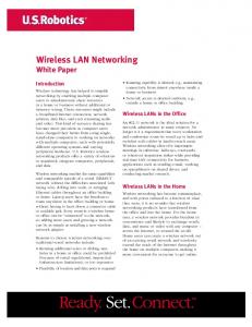
5.5.4 Evaluation of Throughput "Throughput is defined as the rate (requests per unit time) at which the requests can be serviced by the system. Measuring throughput in terms of received packets per second. This metric is calculated for individual receivers and for the overall system"[7]. The throughputs calculated by the QualNet software of both systems are close to each other, i.e., in LMDS is 41220 for node 39 and in WOMN equals to 40961 for the same node, as illustrated in Figure 21. Hence, the WOMN system keeps the throughput proportional with LMDS. However, WOMN decreases average ETE delay. Figure 22 shows the average throughput for both WOMN and LMDS. The difference of 246 bits is very small.
5.6 The Effects of Failure of Some Links in the WOMN and LMDS.
6. Conclusion and Future Works
If five out of the six outer ring links which are connected to the inner nodes fail, what would happen for each system? After simulating the LMDS and WOMN systems with the same link failures, the total bytes received for CBR in LMDS is affected by the failure of links. While, the WOMN is not affected because of its high bandwidth. Figure 23 shows the five failed links during transmitting data. The total bytes received using CBR in the WOMN
This section presents general conclusions that can be drawn from the results of the simulation experiments. One of the main objectives of this paper was to use the simulation models to compare performance of the two systems: LMDS and WOMN. The simulation results clearly show that the WOMN model has better performances than the LMDS model. In the real time execution, WOMN
Average Throughput (bits / second) 41500 41400
bits / second
41300
41207
41200 41100 41000
WOMN
40961
LMDS
40900 40800 40700 40600 WOMN
LMDS Systems
Figure 22: Throughput (WOMN and LMDS )
Figure 23: WOMN and LMDS with 5 failed links with X between failed links
Total bytes received by using CBR in WOMN before and after links damaged
Total bytes received by using CBR in LMDS before and after links damaged
150000
Bytes received
Bytes received
200000 WOMN after links damaged
100000
WOMN before links damaged
50000 0 24
39
46
140000 120000 100000 80000 60000 40000 20000 0
LMDS after links damaged LMDS before links damaged
24
Nodes numbers
39
46
Nodes numbers
Figure 25: Total bytes received using CBR in LMDS after Links damaged very little
Figure 24: Total bytes received using CBR in WOMN before and after links damaged
72
International Journal of Digital Content Technology and its Applications Volume 3, Number 3, September 2009 takes less time than LMDS, for the same simulation time. Total bytes received using VBR and CBR applications in WOMN are more than in LMDS, while the average ETE delay per packet for WOMN is too low compared to LMDS. However, the throughput is still maintained at the same level between WOMN and LMDS. Some advantages of the WOMN system are free frequency license, low cost, easy deployment, better coverage area, huge bandwidth, reliability, and security. The results support the idea of using the WOMN system instead of LMDS, as a solution for the last-mile problem in wireless systems. Using WOMN system prevents slowing down the MAN network, when the numbers of subscribers increases and the use of the real-time multimedia applications such as Interactive games, video conferencing and surveillance by cameras are increased. A future work is to make a comparison between the two systems in different weather environments and use the backup systems discussed in Section 2.
[10] Harry R. Anderson L. Fixed Broadband Wireless System Design John Wiley & Sons; 2003 December. [11] Microwave Signals. [Accessed 2007 October]. Available from URL http://en.www.wikipedia.org/wiki/signal. [12] The Telecommunication Technology Committee (TTC). The Investigation Report of Major Standardization Activities about Broadband Wireless; 2003 February. [13] S. Max et al., Spectrum sharing in IEEE 802.11s wireless mesh networks, Comput.Netw. doi: 10.1016/j.comnet.2007.01.029 [14] Marieke Fi, Harry Bo. Flexibility and broadband evolution. Telecommunications Policy; 2006:424–444. [15] Ali F. Almutairi, Salem Salamah. Spectral efficiency improvement for LMDS systems using adaptive techniques in fading channels. Computers and Electrical Engineering; 2006:299–311 [16] Eric Ko, Issac I, Kim and Bruce Mc. Atmospheric Propagation Characteristics of Highest Importance to Comercil Free Spac Optics. San Diago,CA; 2003 April. [17] Local Multipoint Network Service. [Accessed 2007 October]. Available from URL http://en.www.wikipedia.org/wiki/LMDS. [18] Free Space Optics [homepage on the Internet]. [Accessed 2007 June]. Available from URL http://www.fsona.com. [19] Richmond B. Wavelength selection for optical wireless communication system. CANADA; 2001 February. [20] DragonWave Inc. Engineering for the effects of Rain & Fog on the AirPair System. [updated 2005 July 12; cited 2007 April]. Available from URL www.dragonwaveinc.com. [21] Ian F, Akyildiz a, Xudong Wang b, Weilin Wang b. Wireless mesh networks. Computer Networks; 2005: 445–487. [22] CanonBeam. [Accessed 2007 July]. Available from URL http://www.usa.canon.com/html/industrial_canobeam/c anobeam/customertestimonials.html. [23] Zhigang Zh, Weihong Li. Integration of Laser Vibrometry with Infrared Video for Multimedia Surveillance Display. Computer Science Department. New York: 2004: 0704-0788. [24] Richmond B. Defining a Common Standard for Evaluating and Comparing Free-Space Optical Products. CANADA; 2001 February. [25] Phillips R L, Andrews L C. Laser Beam Propagation Through Random Media SPIE Prss:1998;5(6):914-925. [26] Yashwanth He. Optical Wireless Networks. Dept of ECE, IISc, Bangalore; 2006 January. [27] Osaac I. Kim andEric Korevaar. Availability of Free Space Optics (FSO) and hybrid FSO/RF systems. San Diego: Morgan Kaufmann Publishers; 2001: 21-26. [28] Scalable Network Technologies, Inc. QualNet 4.0 Programmer’s Guide, Center Drive West. LA, CA 90045; 2006 November. [29] Jacqueline H. Carrillo, Scott E. Emert, D. Sherman El, and Jeffrey L. An Economical Optical Fog Detector. Department of Atmospheric Science, Colorado State University, Fort Collins, Colorado USA; 2005 April.
7. References [1] [2]
[3] [4] [5]
[6] [7]
[8]
[9]
Lillian GO. Telecommunications Essentials. Second Edition. USA: Addison Wisely; 2001: 61-75 Optical Access OA. Comparison between a Meshed Wireless Optical Access Network and a Reference LMDS Alternative. [Accessed 2007 April]. Available from URL http//www.mrv.com/library/library.php?ctl=MRV-WPComparisonMesh.pdf. Jhun D, Ralaph D, Jim L, Arthur T. Cisco Networking Academy Program CCNA 1 and 2. Third Edition. Indiana, USA: Cisco Press; 2004 August: 128-165 Kuran M, Tugcu T. A survey on emerging broadband wireless access technologies. Comput. Netw. doi: 10.1016/j.comnet.2006.12.009. Bo Han A, Weijia Jia B, Lidong Lin B. Performance evaluation of scheduling in IEEE 802.16 based wireless mesh networks. Computer Communications; 2007: 782–792 Web ProForums. Local Multipoint Distribution System. [Accessed 2007 April]. Available from URL http://www.iec.org/online/tutorials/lmds/topic01.htm Khobare A. Simulation Study of Local Multipoint Distribution Service LMDS [dissertation]. Raleigh: Virginia Polytechnic Institute and State University; 2000 Agrawal R, Imielinski T, Swami A IEEE Standard for Local and Metropolitan Area Networks Part 16: Air Interface for Fixed Broadband Wireless Access Systems. 2002 April. Clear Mesh Network. Video, Physical Security and IT Infrastructure Finally Converge on Wireless Optical Mesh. [Accessed 2007 April]. Available from URL http://www.clearmesh.com.
73