Journal of ELECTRICAL ENGINEERING, VOL. 59, NO. 4, 2008, 169–177
IMPROVEMENT OF SYNCHRONOUS AND ASYNCHRONOUS MOTOR DRIVE SYSTEMS SUPPLIED BY PHOTOVOLTAIC ARRAYS WITH FREQUENCY CONTROL Laid Zarour — Rachid Chenni — ∗ Abdelhalim Borni — Aissa Bouzid The dynamic performances of a permanent magnet synchronous motor (PMSM) and an asynchronous motor (ASM) connected to a photovoltaic (PV) array through an inverter are analyzed. The mathematical models of PV array, inverter/motor and controller are developed. The photovoltaic array is represented by an equivalent circuit whose parameters are computed using experimentally determined current-voltage ( I − V ) characteristics. The necessary computer algorithm is developed to analyze the performance under different conditions of the solar illumination for a pump load. The study also examines the effectiveness of the drive system both for starting and DC link voltage fluctuations caused by varying solar illumination. K e y w o r d s: solar energy, optimization, photovoltaic arrays, pumping, modelling, efficiency
1 INTRODUCTION
Several authors lent much attention to the study of the dynamic performance of the photovoltaic pumping systems. Appelbaum and Bany [1] analyzed the performance of a direct motor with separate excitation fed by a photovoltaic generator. Later, Appelbaum [2] studied the dynamic behaviour of a photovoltaic panel associated directly with a DC motor with excitation series. Roger [3] showed that a load such centrifugal pump, driven by a DC motor, represents a load matched to the characteristics of PV generator. In a former work, the dynamic performance of a PV generator involving a system, permanent magnet motor associate at a centrifugal pump, was studied by Anis and Metwally [4]. Recently Betka [5] presented the performance optimization of an asynchronous motor associated at a PV generator. In this work, the dynamic performance of a system which uses, once a synchronous motor with permanent magnet and another time an asynchronous motor, is studied. For this last type of engine, the primary current and flux changes in accordance with the changes in the applied voltage. It is not the case with the permanent magnet synchronous motor where flux is constant. The electric model of the system is simulated using the software MATLAB 6p5 for various solar illuminations and temperatures
2 ELECTRICAL MODEL FOR A PHOTOVOLTAIC CELL
The electrical model of a solar cell is composed of a diode, two resistances and a current generator [6], [7],
[8]. The relationship between the voltage V (V) and the current I (A) is given by ³ ´ V +R I V + RS I S I = IL − I0 exp −1 − , (1) A RP where IL , I0 and I are the photocurrent, the inverse saturation current and the operating current, RS and RP are series and parallel resistances, respectively, which depend on the incident solar radiation and the cell temperature. A = KT q is the diode quality factor. K and q are Boltzmann constant and electronic charge respectively. Townsend (1989), Eckstein (1990), Al-Ibrahimi (1996), propose the model with four parameters assuming that the parallel resistance is infinite – so (1) can be rewritten as ³ ´ V + RS I I = IL − I0 exp −1 . (2) A The current and the voltage parameters of the PV generator are: Ipv = I and Vpv = ns Ns V , where ns , Ns are the numbers of series cells in the panel and of the series panels in the generator ( ns = 36). Now only the four parameters IL , I0 , Rs and A need to be evaluated, a method to calculate these parameters has been developed by Townsend (1989) and Eckstein (1990), Duffie and Beckman (1991). Since there are four unknown parameters, four conditions of the current I and the voltage V are needed. Generally, available manufacturer’s information are set at three points at the reference conditions, G = 1000 W/m2 and T = 25 ◦C, the voltage at open circuit Voc,ref , the current at short circuit Isc,ref and the maximum power point Vmp,ref and Imp,ref . The 4th condition comes from the knowledge of the temperature coefficient µIsc at short circuit and µVoc at open circuit. Eq is the band gap energy ( 1.12 eV) The following
∗ Laboratoire d’´ electrotechnique Facult´ e des sciences de l’ing´ enieur Universit´ e Mentouri de Constantine, Alg´ erie;
[email protected],
[email protected]
c 2008 FEI STU ISSN 1335-3632 °
170 L. Zarour — R. Chenni — A. Borni — A. Bouzid: IMPROVEMENT OF SYNCHRONOUS AND ASYNCHRONOUS MOTOR . . . T (◦K) [7] and can be estimated by the following equation. For a given radiation and temperature, the cell parameters are then calculated from ¢³ GT ¡ ηc ´ Tnoct − Ta 1 − , GTnoct τα ª G © IL,ref + µIsc (Tc − Tref , IL = Gref ³ T ´3 hn E ³ Tc,ref ´i s q I0 = I0,ref exp 1− , Tref A Tc T = Ta +
Fig. 1. Equivalent circuit of PV cell
Rs = Rs,ref , A = Aref
(7) (8) (9) (10)
Tc . Tc,ref
(11)
Here, Ta — ambient temperature. ηc — cell efficiency. Tnoct — nominal operating cell temperature and τα — transmittance absorbance product. These four parameters, for ambient conditions, are found from the equations (7) to (11). By injecting these parameters in the equation (2), we obtain I − V characteristics.
Fig. 2. Block diagram of the global system
PV Array Characteristics: Ns = 11 panels in series GTO136 – 80/2, AM = 1.5 , Pm = 80 W, Voc,ref = 21.5 V, Isc = 4.73 A. Impref = 4.25 A, Vmpref = 16.9 V, Tnoct = 45 ◦C, Gref = 1000 Watt/m2 , Tref = 298◦K . µIsc = 3 × 10⁻³ A/ ◦C, µVoc = 82 × 103 V/ ◦C. 3 GLOBAL SYSTEM MODELLING Fig. 3. PMSM three phase model
equations, (3) to (6), are used to calculate the parameters of the photovoltaic cells in a standard condition based on the experimental data.
Rs,ref =
¡ Aref ln 1 −
A=
Imp,ref IL,ref
µVoc Tc,ref
¢
− Vmp,ref + Voc,ref
Imp,ref − Voc,ref + Eq ns
Tc,ref µIsc IL,ref
−3
.
, (3) (4)
From equation (2) at reference condition and short circuit point, the diode current I0 is very small (in the order to 10−5 at 10−6 A), so the exponential term is neglected. Isc,ref ∼ = IL,ref , I0,ref =
I ¡ VL,ref ¢ sI exp +R −1 A
(5) (6)
The indices oc, sc, mp and ref refer to the open circuit, the short circuit, the maximum power and the reference condition respectively. The cell parameters change with the solar radiation G(W/m2 ) and ambient temperature
The decomposition of the total system in elementary blocks is related directly to the physical function of the block. 3.1 PMSM electrical model The model of the synchronous motor (PMSM) represented by the three fixed stator windings and the permanent magnet rotor is in Fig. 3. The mathematical dynamic model of a PMSMotor can be described by the following equations in a synchronously rotating d– q reference frame (Grellet and Clerc, 1997), [9] where Vd and Vq , Ld and Lq , id and iq are stator voltages, inductances, and currents components in the (d, q) axis respectively; Ra is the stator resistance per phase, Φf is the rotor flux linkage due to the rotor permanent magnet frame, and pp is the number of pole pairs. For a synchronous machine we have ωr = ω (ω — is the electric pulsation). Using the Park transformation, we pass from the real sizes ( Va , Vb , Vc and ia , ib , ic ) to their components ( Vo , Vd , Vq and ( io , id ,iq ). The Park matrix is expressed by [9] r [P (θ)] =
√1 2 3
2 √1 2 √1 2
cos θ − sin θ ¢ ¡ ¢ ¡ cos θ − 23 π − sin θ − 32 π , (12) ¡ ¢ ¡ ¢ cos θ − 43 π − sin θ − 34 π
171
Journal of ELECTRICAL ENGINEERING 59, NO. 4, 2008
4 VECTORIAL COMMAND PRINCIPLE
From equation (15), the torque control is made on the components of current id and iq . The electromagnetic torque depends only on component iq . It is maximum for a given current if we impose id = 0 . The obtained torque is then proportional to the current of the machine power supply as in the case of a separately excited DC motor, Cem = pp Φf iq . Fig. 4. Block diagram of the speed and current regulators
5 REGULATORS
or in matrix form ¸· ¸ · ¸ · id Vd Ra −Lq ω = iq Vq Ld Ra ¸ · ¸ · · ¸ Ld 0 d id 0 + + . (13) 0 Lq dt iq Φf ω Moreover, the PMSM developed electromagnetic torque is given by the following equation Cem =
o 1 n d [is ] [L] [is ] . 2 dθm
(14)
With θe = θm pp , θe , θm the electrical angle and mechanical respectively, the electromagnetic torque is Cem = pp b(Ld − Lq )id + Φf ciq .
(15)
For a synchronous machine with smooth poles ( Ld = Lq ), the torque will be Cem = pp Φf iq . The mechanical equation is written dw J + f ω = Ce − Cr dt
1+
2ξ ωn p
+
p2 ω2 n
we obtain J 1 = 2, Ki ωn
2ξ Kp + f = . ωn Ki
(18,19)
6 DESCRIPTION OF THE GLOBAL SYSTEM
(16)
where f and Cr are the friction coefficient and the resistant torque respectively. PMS Motor Characteristics: P = 746 Watts, w = 188.95 rad/s, V = 208 V, Is = 3 A, f = 60 Hz, Isn = 5 A, Ra = 1.93 Ω , Ld = 0.0424 H, Lq = 0.00725 H, Ψ = 0.003 Wb, J = 3 × 10⁻³ Kg/m2 , pp = 2 . PI parameters: For speed: Ti = 0.01 , Kp = 1 . For current: Ti = 10, Kp = 5 . 3.2 Inverter model For a three phase equilibrated system, we have: (Van + Vbn + Vcn = 0 and V1m + V2m + V3m = 3Vnm ). In matrix form 2 1 1 Van 3 −3 −3 2 1 Vbn = − 1 [Vpv ] . (17) 3 3 −3 1 2 1 Vcn −3 −3 3 Vpv is the photovoltaic generator voltage.
To optimize the system with given performances, the system must be controlled. The first role of a regulation system is to oblige the controlled parameters (output of the system) to preserve values as close as possible as those which one chooses like references values. Generally the control devices are with closed loop. For this command, there are three correctors PI used to control the speed and the two components of the stator current. The closed speed loop can be represented by Fig. 4. This transfer function in closed loop has a dynamics of 2nd order. By identifying the denominator with the canonical form 1
Figure 5 represents the total diagram of the vectorial command of a PMSM in a reference mark (d, q). The reference of the forward current Id∗ is fixed at zero and the output of the speed regulator Iq∗ constitutes the instruction of the torque. The forward reference currents Id∗ and Iq∗ are compared separately with the real currents Id and Iq of the motor. The errors are applied to the input of the traditional PI regulators. A decoupling block generates the standards reference voltage Vd∗ , Vq∗ . The system is provided with a regulation speed loop which makes it possible to generate the reference of current Iq∗ . This reference is limited to the maximum current. On the other hand, the forward reference current Id∗ is imposed null in our case. The outputs of the currents regulators Id and Iq in the reference mark (a, b, c) are used as references of the voltage (Va∗ , Vb∗ , Vc∗ ) for the inverter control which feeds the PMSM. From the matrix form (13) we pose Ud = Vd + ed , Uq = Vq + eq and p = d the differential operator. dt With ed (p) = ωLq iq and eq (p) = −ωLd id + ωΦf , we can write the following transfer function
172 L. Zarour — R. Chenni — A. Borni — A. Bouzid: IMPROVEMENT OF SYNCHRONOUS AND ASYNCHRONOUS MOTOR . . .
Fig. 5. Block diagram of the PMSM and the GPV
Fd (p) =
Id (p) 1 = , Vq (p) + ed (p) Ra + pLd
(20)
7 ASYNCHRONOUS MOTOR MODEL
Fq (p) =
1 Iq (p) = . Vq (p) + eq (p) Ra + pLq
(21)
The mathematical dynamic model of the asynchronous motor is described by the equations set [8–11], [13]
The compensation causes to uncouple the two axes thanks to a reconstitution in real time from these reciprocal disturbances (ed (p) and eq (p)). Under such conditions, the system becomes linear, we obtain: Vq0 = Vd + ωLq iq = (Rq + pLd )id , Vq0
(22)
= Vq − ωLq id − ωΦf = (Rq + pLq )iq . (23)
Therefore the two axes are well uncoupled; the axis d does not depend to any more an axis q . Thus, Vd∗ = Vd0 − ωLq iq , Vq∗
=
Vq0
− ωLd id + ωΦf .
(24) (25)
For a damping coefficient, for PMSM, ξ = 0.7, and ωn trep = 3 , trep representing the response time of speed, the transfer functions for current id and current iq of the system in open loop are respectively, see Fig. 5.
with τd =
Rs Ld
Hd (P ) =
G0 Cd (p) , Rs (1 + τd p)
(26)
Hq (P ) =
G0 Cq (p) Rs (1 + τq p)
(27)
and τq =
Rs Lq
.
The proportional-integral regulators PI (Cd (p)Cq (p) ), whose transfer functions are given by: Cd (p) = Cq (p) = K(1 + τd p)/p
(28)
with K = Rs /(2G0 TS ) . Here, G0 , TS are gain coefficient and the sampling frequency.
dIsd 1 h ³ M 2 Rr ´ Isd + ws σLs Isq = − Ra + dt σLs L2r i M Rr M + Φrd + wm Φrq + Vsd , Lr Lr M dIsq 1 h ³ M 2 Rr ´ Isq − = − Ra + wm Φrd 2 dt σLs Lr Lr i M Rr + Φrq − σws Ls Isd + Vsq , Lr dΦrd Rr M Rr =− + (ws − wm )Φrq + Isd , dt Lr Lr dΦrq Rr M Rr =− − (ws − wm )Φrd + Isq , dt Lr Lr dw = Te − Tr . J dt
(29)
(30) (31) (32) (33)
In this case, the ASM develop an electromagnetic torque Te expressed as follows Te =
¢ M p2p ¡ Isq Φrd − Isd Φrq . Lr
(34)
d, q axes are corresponding to the synchronous reference frame, Ls , Lr , Ra , Rr and M are — stator and rotor main inductances, resistances and intrinsic selfinductance respectively. J is total inertia, σ dispersion factor. Isd , Φrd , Isq , Φrq are d-axis stator current, rotor flux and q -axis stator current, rotor flux respectively. ws and wm are the angular speed of the rotating magnetic and electric fields. AS Motor Characteristics: P = 746 Watts, f = 60 Hz, Isn = 3.4 A, Te = 5 Nm.
173
Journal of ELECTRICAL ENGINEERING 59, NO. 4, 2008
Fig. 6. Block diagram of an ASM vectorial command
Fig. 7. Simulation results of speed, stator current per phase and motor torque
Ra = 4 Ω , Ls = 0.3676 H, Rr = 1.143 Ω, Lr = 0.3676 H, M = 0.3439 H, J = 3 × 10⁻² Kg/m2 , pp = 2 . PID parameters: Ti = 0.9 , Kp = 3 .
of speed, the transfer function for current isd and isq of the system in open loop is 1 , Ra (1 + τs p) Ki C(p) = Kp + p
H(p) = C(p)
8 GLOBAL SYSTEM
For a damping coefficient, for ASM, ξ = 1, and ωn trep = 4.75, trep — representing the response time
with τs = parameters.
Ra Ls
(35) (36)
, Ki and Kp the proportional-integral
174 L. Zarour — R. Chenni — A. Borni — A. Bouzid: IMPROVEMENT OF SYNCHRONOUS AND ASYNCHRONOUS MOTOR . . .
Fig. 8. Simulation results of speed, flux and stator current
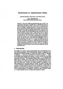
9 SIMULATION RESULTS OF THE PMSM
10 SIMULATION RESULTS OF THE ASM
In this section, the simulation results of the optimization of a photovoltaic pumping system fed by electrical synchronous motor coupled with a centrifugal pump are presented
If we apply during every 1 second two levels of solar radiation G=1000W/m 2 and G=450W/m 2 . Simulation results are carried out to verify the performance of fieldoriented control, with and without optimization, the flux command is set to Φrd =0.8 Wb and Φrq =0 Wb, see Fig. 9.
If we apply during every 1 second two levels of solar radiation G =1000W/m 2 and G=450 W/m 2 , simulation results are carried out to verify the performance of fieldoriented control, the system is stabilized on the level of the reference variables. The first stage of solar radiation corresponding to G=1000W/m 2 at the optimization does not affect the various studied quantities. The speed is about 189 rad/s, the direct stator current value id =0A, iq =6A, the stator current isa =3.4 A, the torque is about 3.95 Nm Fig. 8. At the second stage of solar radiation corresponding to G=450W/m 2 , the optimization affect the various studied quantities. The speed is about 135 rad/s, the value of the direct stator current id =0 A, iq =3 A, the stator current isa =2 A and the torque is about 1.98 Nm Fig. 8. The studied various quantities prove the performance of our system.
The first stage of solar radiation corresponding to G=1000W/m 2 , has no effect on the optimization of various studied quantities. The speed is about 180 rad/s, the value of the direct stator current isd =3 A, isq =3.2 A and the stator current isa =3.2 A. Also in spite of the step changes in the external load torque, the rotor speed and rotor flux tracking are successfully achieved. It is important to note that, even though the power provided by the photovoltaic generator is lower than its maximum, this result has motivated the use of DC/AC inverter for ensuring the desired maximum power point tracking, which essentially keeps the convergence power at its optimal value. In order to test the efficiency of the proposed method, we also carried out some simulations when the photovoltaic generator is able to operate around working optimal point.
175
Journal of ELECTRICAL ENGINEERING 59, NO. 4, 2008
Fig. 9. Flow rate characteristics
Fig. 10. I-V and Loads characteristics
12 CENTRIFUGAL PUMP MODEL
The head-flow rate H − Q characteristic of a monocellular centrifugal pump is obtained using Pleider-Peterman model [14], [15]. The multispeed family head-capacity curves are shown in Fig. 9 and can be expressed approximately by the following quadratic form: h = a0 wr2 − a1 wr Q − a2 Q2
(40)
with a0 , a1 , a2 are coefficients given by the manufacturer. The hydraulic power and the resistive torque are given by, PH = ρgQH , Fig. 11. Operation points of the PV pumping
2
Cr = kr Ω + Cs .
11 LOCATION OF MAXIMUM POWER POINTS
The generator power is equal to Ppv = Vpv Ipv and the maximum power is obtained for: P 0 Ypv I 0 Ypv = Vpv + Ipv = 0 . V 0 Ypv V 0 Ypv
(37)
Let Imp be the value of optimal current when power is
(41) (42)
where Q — is the water flow (m3 /s ) and H — is the manometric head of the well (m). Centrifugal pump parameters: ωn = 150 rad/s, a1 = 4.923410−3 m/(rad/s)2 , a2 = 1.5826 × 10⁻⁵ m/(rad/s) (m2 /s). a3 = −18144 m/(m3 /s)2 , Canalisation parameters: H = 10 m, l = 7.4 m, d = 0.006 m, g = 9.81 m2 /s, ρ = 1000 kg/m3 .
I0Y
maximum. By substituting V 0 Ypv , Vpv and Ipv by their pv values in (37), we obtain the following equation: i h ³ ´ I −I I R (Imp − IL − I0 ) ln L I0 mp + 1 − mpA s Imp + = 0. ¡ ¢I R 1 + IL + Imp + I0 mpA s (38) The solution of the equation (38) by the Newton-Raphson method in motor-pump coupling mode, is governed by the following equation Imp Vmp = pΦωiq ηc ηm ηp .
(39)
ηc , ηm , ηp , are respectively the inverter efficiency, motor efficiency and pump efficiency.
13 ILLUMINATION’S INFLUENCE ON WORKING OPTIMAL POINT
While keeping the power generator at constant value, the optimization system improves the motor efficiency which will work around the working optimal point of the generator, Fig. 10. The optimization system improves the motor efficiency which will work around the working optimal point of the generator; the load motor power characteristic will slip towards the band of the generator maximum powers, which ranges between 180 and 220 volts, for a variable illumination levels between 250 w/m2 and 1100 w/m2 , Fig. 11.
176 L. Zarour — R. Chenni — A. Borni — A. Bouzid: IMPROVEMENT OF SYNCHRONOUS AND ASYNCHRONOUS MOTOR . . .
Fig. 13. Flow rate of PV pumping
Fig. 12. Speeds of PV pumping driven by PMSM (1) and an ASM (2)
Fig. 14. Global efficiency of PV pumping.
For the direct coupling the driving system motorpump functions only start from 250 w/m2 for ASM and 300 w/m2 for PMSM, contrary to the optimized coupling whose splashing phase ceases starting from 100 w/m2 , Figs. 13 and 14. For a temperature T = 298◦K, and an illumination G = 450 w/m2 , the power gain is 49.32 % for PMS Motor and 25.23 % for AS motor, after optimization, it will be 20.12 % for PMSM and 7.35 % for ASM at 900 w/m2 . Optimization is better for weak illuminations, until 600 w/m2 , the global efficiency of the complete system generator, motor-pump being weak, approximately between 7 % and 8 % . 14 CONCLUSION
We showed the principal characteristics of a photovoltaic system allowing the pumping of water with solar energy. A PV generator outputting on an electronic power inverter detecting the working optimal point is presented. This generator drives a synchronous permanent magnet motor with smooth poles firstly and an induction motor
that by using the vectorial command principle in the reference (d, q). This method makes it possible to obtain very good performances similar to those of a DC motor, because one obtains an electromagnetic torque directly proportional to the current absorptive by the load. For achieving better motor torque generating characteristics, the conventional PI controller has been introduced in this paper for the vectorial command of an ASM machine fed by a photovoltaic generator. A current control scheme combining a decoupling control to achieve a fast dynamic response in a field orientation-controlled induction motor drive was presented in this paper. The ASM machine drive with rotor flux, stator current and speed controllers has exhibited good transient and steadystate performance. The results show the flux magnitude has been maintained as constant and a torque exhibits a fast response. In this paper to take advantage of the field orientedcontrol, the flux and current controller have been designed using stator and rotor equations in the rotor flux frame since the flux and current controllers have simple forms according to the choice of closed-loops transfer functions, they can be easily designed and implemented. On the other hand, the control of the duty ratio is achieved by using the integral controller. The use of this controller gives good results for the maximum power tracking. A comparative study was carried out on the systems described in Mimouni and al [16] and Duzat [17]. The simulation results show that an increase of both the daily pumped quantity and pump efficiency are reached by the proposed approach. In addition, the generator voltages control law leads to a less expensive and noncomplex implementation. Thus the advantages described are acquired meanwhile overriding their inconvenience. Nomenclature q K Eg V
— Electron charge (1.9 ×10⁻¹⁹ C) — Boltzmann constant (1.38 ×10⁻²³ J/K) — Material band gap energy (1.12 eV) — Output generator voltage (V)
Journal of ELECTRICAL ENGINEERING 59, NO. 4, 2008
I Isc I0 RS RP Imp Vmp Voc Pmax G µV oc
— Generator current (A) — Short-circuit current (A) — Reverse saturation current (A) — Series resistance of PV cell ( Ω ) — Parallel resistance of PV cell ( Ω ) — Maximum point current (A) — Maximum point voltage (V) — Open circuit voltage (V) — Maximum power of PV panel (W) — Solar irradiance ( W/m2 ) — Temperature coefficient of open-circuit voltage — (A/ ◦C) µIsc — Temperature coefficient of short-circuit current — (V/ ◦C ) Noct — Nominal Operating Cell Temperature Ns , Np — Number of cells in series and in parallel Vmot — Motor voltage (V) Rsa — Stator resistance per phase ( Ω ) Ld — d -axis self inductance of the stator (H) Lq — q -axis self inductance of the stator (H) M — Mutual inductance (H) ω — Motor angular speed (rad/s) ωs — Angular speed of magnetic field (rad/s) ωm — Angular speed of electric field (rad/s) H — Total head (m) Hg — Geodetic head (m) Q — Flow rate ( m3 /s ) ρ — Water volumic mass (kg/m3 )
References [1] APPELBAUM, J.—BANY, J. : Performance Characteristics of a Permanent Magnet DC Motor Powered by Solar Cells, Sol. Energy 22, (1979), 439. [2] APPELBAUM, J.—SHARMA, M. S. : The operation of permanent magnet dc motors powered by a common source of solar cells, IEEE Trans. Energ. Convers. 4 No. 4 (1989), 635–642. [3] ROGER, J. A. : Theory of the Direct Coupling between DC Motors and Photovoltaic Solar Arrays, Sol. Energy 23 (1979), 193. [4] ANIS, W.—METWALLY, H. M. B. : Dynamic performance of a directly coupled PV pumping system, Sol. Energy 53 No. 3 (1994). [5] BETKA, A.—MOUSSI, A. : Performance optimization of a photovoltaic induction motor pumping system, Renewable Energy 29 (2004), 2167–2181. [6] HUA, C.—LIN, J.—SHEN, C. : Implementation of a DSP Controlled Photovoltaic System with Peak Power Tracking, IEEE Trans. Ind. Electronics 45 No. 1 (Feb 1998), 99–107. [7] MULJADI, E. : PV Water Pumping with a Peak Power Tracker using a Simple Six Step Square-Wave Inverter, IEEE Trans. Industry Applications 33 No. 3 (May/June 1997), 714–721. [8] MIMOUNI, M. F.—DHIFAOUI, R.—BRUDNY, J. F.—ROGER, D. : Field-oriented control of double-star induction machine, Int journal system of analysis modelling simulation (SAMS) 37 (2000), 181–202. [9] GRELLET, G.—CLERC, G. : Actionneurs Electriques Principes Mod` eles Commande, Eyrolles, 1997. [10] BOSE, B. K. : A High performance Inverter — Fed Drive System of Interior Permanent Magnet Synchronous Machine, IEEE Trns Appl, Ia-24 (Nov/Dec.1998), 97–997. [11] JAHNS, T. M. : Flux — Weakening Regime Operation of an Interior Permanent Magnet Synchronous motor Drive IEEE on IA.
177 [12] KIN, J. M.—SUL, S. K. : Speed Control of Interior Permanent Magnet Synchronous motor Drive for Flux Zeaking Operation 3, in Proc. IEEE IAS Annuel: eet mpp. 216–221, 1995. [13] MURPHY, J. M. D.—TURNBULL, F. G. : Power electronics control of AC motor, Pergamon Press, 1985. [14] HAMIDAT, A.—HADJ ARAB, A.—CHENLO, F.—ABELLA, M. A. : Performances costs of the centrifugal and displacement pumps, pp. 19511954, WREC, 1998. [15] MOUSSI, A.—BETKA, A.—AZOUI, B. : Optimum design of photovoltaic pumping system, Leicester, UK, UPEC99; 1999. [16] MIMOUNI, M. F.—MANSOURI, M. N.—BENGHANEM, B.— ANNABI, M. : Vectorial command of an asynchronous motor fed by a photovoltaic generator, Renewable Energy 29 (2004), 433–442. [17] DUZAT, R. : Analytic and experimental investigation of a photovoltaic pumping system, PhD thesis, Oldenburg University 2000.
Received 15 January 2007 Rachid Chenni was born in Constantine, Algeria, in 1957. He received the diploma of electrotechnology engineer in 1983 at the science and Technology University of Oran, Master degree (with honors) in electronics, (1996) and his PhD in Physics Energetic from the University of Constantine in Algeria (2006). Since 1996 he has been an Assistant Professor, at the Faculty of Engineering, University Mentouri of Constantine. His main scientific interests are in the fields of circuit theory and applications and power electronics, also his study is about the photovoltaic systems and their applications. Laid Zarour was born in Constantine, Algeria, in 1976. He received the diploma of electrotechnology engineer in 2002 at the science and technology of Mentouri University of Constantine, Master degree (with honors) in electrotechnics, (2005). He is currently preparing his doctor studies in renewable energy at the Mentouri University, Constantine, Algeria. From 2005, his main scientific interests are in the fields of circuit theory and applications and power electronics, also his study is about the photovoltaic systems and their applications. Aissa Bouzid was born in Constantine, Algeria, in 1954. He received the diploma of electrotechnology engineer in 1980 at the science and Technology University of Algiers, Master degree electronics, (1985) and his PhD in Electrotechnology from Orsay University of Paris in France (1994). Since 1996 he has been a Professor, at the Faculty of Engineering, University Mentouri of Constantine. His main scientific interests are in the fields of circuit theory and applications and power electronics, also his study is about the photovoltaic systems and their applications Abdelhalim Borni was born in Biskra, Algeria, in 1977. He received the diploma of electrotechnology engineer in 2003 at the science and technology of Mohamed Khider University of Biskra, Master degree (with honors) in electrotechnics, (2008). He is currently preparing his doctorat in renewable energy at the Mentouri University, Constantine, Algeria. His study is on the photovoltaic systems and their applications.