The main objective of this work is to design and implement a vector control system ... vector control system based on the combustion pressure purge and through.
TREBALL FI DE CARRERA
TÍTOL DEL TFC: Millores en un sistema de control vectorial per a una mini-llançadora basat en materials compostos TITULACIÓ: Enginyeria Tècnica Aeronàutica, especialitat Aeronavegació AUTOR: Alí Beizaee DIRECTOR: Joshua Tristancho Martínez DATA: 27 de Juny de 2013
Título: Mejoras en un sistema de control vectorial para una mini-lanzadera basado en materiales compuestos Autor: Alí Beizaee Director: Joshua Tristancho Martínez Fecha: 27 de Junio de 2013
Resumen El objetivo principal de este trabajo es diseñar e implementar un sistema de control vectorial basado en gas frío que sea muy ligero, fácil de construir y fiable; si hay tiempo, además probarlo. El trabajo es una continuación de un TFM en el que se estudiaba un sistema de control vectorial basado en la purga de presión de combustión y a través de cuatro micro-válvulas y unas pequeñas toberas se le daba 6 grados de libertad en el eje X, Z y rotación a través del eje Y; siendo el eje Y la dirección de vuelo. La mejora consiste en utilizar materiales compuestos para que, a través de un molde y pequeñas operaciones de mecanizado se controle el paso del gas licuado, se permita expandir dicho gas y a través de una tobera acelerar a la máxima velocidad posible el gas para lograr el mayor impulso específico. Este trabajo final de carrera se realiza en colaboración con el grupo WikiSat. El sistema de control vectorial será utilizado en la lanzadera WikiLauncher que pone pequeños satélites en órbita (Hasta 6 femto-satélites). De esta manera será posible hacer algunas pruebas de concepto e intentar validar el sistema, por lo menos con pruebas estáticas. Si el tiempo lo permite se realizarán pruebas reales en vuelo como parte del programa de espacio del grupo WikiSat.
Palabras clave: Gas frío, Materiales compuestos, Mini-lanzadera, Femto-satélite
Title: Improvements of a vector control system for a mini-launcher based on composite materials Author: Alí Beizaee Director: Joshua Tristancho Martínez Date: Juny, 27th 2013
Overview The main objective of this work is to design and implement a vector control system based on cold gas that is very light, easy to build and reliable; to test it if on time. The work is a continuation of a Master Thesis about a studied of a vector control system based on the combustion pressure purge and through four micro-valves and tiny nozzles gave 6 degrees of freedom in the X and Z axes and rotation through the Y axis, being the Y axis the direction of flight. The improvement is to use composite materials for which, through a casting of a resin and few machining operations, the liquefied-gas passage is controlled, expanded, and through a nozzle, the gas is accelerated to the highest possible speed to achieve the higher specific impulse. This final bachelor work (TFC) is in collaboration with the WikiSat group. The vector control system will be used in the WikiLauncher. This launcher is able to put up to six small satellites (femto-satellites that are less than 100 grams of mass). That way it will be possible to do some proof of concept and try to validate the system, at least in static tests. If time permits, additional real flight tests will be performed as part of the WikiSat space program.
Keywords: Cold-gas, Composite materials, Mini-launcher, Femto-satellite
7
Improvements of a vector control system for a mini-launcher based on composite materials
INDEX ACRONYMS, ABBREVIATIONS AND DEFINITIONS .................................... 15 INTRODUCTION .............................................................................................. 17 CHAPTER 1.
WIKISAT MISSION ................................................................. 19
1.1
State of the art .......................................................................................................... 19
1.2
WikiSat Space Program ........................................................................................... 19
1.3
WikiLauncher rocket ................................................................................................ 20
1.4
Cold gas method for the vector control system ................................................... 21
CHAPTER 2.
SYSTEM REQUIREMENTS .................................................... 23
2.1
System requirements .............................................................................................. 23
2.2
High level requirements .......................................................................................... 23
2.3
Low level requirements ........................................................................................... 23
CHAPTER 3.
INTERFACE PROPOSALS .................................................... 25
3.1
Baseline ideas .......................................................................................................... 25
3.2
Component selection .............................................................................................. 26
CHAPTER 4.
SPIRAL SYSTEM DESIGN ..................................................... 29
4.1
Prototype number 1 ................................................................................................. 29
4.2
Prototype number 2 ................................................................................................. 30
4.3
Prototype number 3 ................................................................................................. 31
4.4
Prototype number 4 ................................................................................................. 32
4.5
Prototype number 5 ................................................................................................. 32
4.6
Prototype number 6 ................................................................................................. 32
4.7
Prototype number 7 ................................................................................................. 32
4.8
Summary of the spiral ............................................................................................. 33
CHAPTER 5.
SYSTEM MODELING ............................................................. 35
5.1
Computed Added Design model ............................................................................ 35
5.2
Drawings ................................................................................................................... 36 5.2.1 Vector control assembly sketches ........................................................................ 36
Índex
8
5.2.2 5.2.3 5.2.4 5.2.5 5.3
Other assembly sketches ..................................................................................... 37 WikiLauncher part list ........................................................................................... 38 WikiLauncher configurations ................................................................................ 39 Payload and inter-stage assembly ....................................................................... 41
Computational Fluid Dynamics simulations ......................................................... 42
CHAPTER 6.
SYSTEM IMPLEMENTATION ................................................ 45
6.1
Manufacturing process ........................................................................................... 45
6.2
System performances ............................................................................................. 45
6.3
Example of trajectory .............................................................................................. 46 6.3.1 Config1. Inertial matrix with single light stage1 and 4 mm nozzle........................ 47 6.3.2 Config2. Inertial matrix with double light stage1 and 4 mm nozzle ...................... 47 6.3.3 Config3. Inertial matrix with heavy stage1 and 4 mm nozzle ............................... 48 6.3.4 Config4. Inertial matrix with heavy stage1 and 9 mm nozzle ............................... 48
6.4
Static flight test ........................................................................................................ 48 6.4.1 Hardware-in-the-loop experiment setup ............................................................... 48 6.4.2 Results .................................................................................................................. 50
CHAPTER 7.
CONCLUSIONS ...................................................................... 51
7.1
General conclusions ................................................................................................ 51
7.2
System conclusions ................................................................................................ 51
7.3
Future work............................................................................................................... 52
7.4
Environmental impact ............................................................................................. 52
CHAPTER 8.
BIBLIOGRAFÍA ...................................................................... 53
ANNEXES. REFERENCE SYSTEMS AND ITS APPLICATIONS ................... 57 ANNEXES. CFD SIMULATION SUPERSONIC SOLVER. ALPHA=0º ........... 58 ANNEXES. CFD SIMULATION SUPERSONIC SOLVER. ALPHA=5º ........... 60 ANNEXES. CFD SIMULATION SUPERSONIC SOLVER. ALPHA=10º ......... 62 ANNEXES. CFD SIMULATION. VECTOR CONTROL FLOW. PITCH ............ 64 ANNEXES. CFD SIMULATION. VECTOR CONTROL FLOW. YAW .............. 65 ANNEXES. CFD SIMULATION. VECTOR CONTROL FLOW. ROLL ............. 66 ANNEXES. WIKILAUNCHER CONFIGURATION 1 ........................................ 67
9
Improvements of a vector control system for a mini-launcher based on composite materials
ANNEXES. WIKILAUNCHER CONFIGURATION 2 ........................................ 68 ANNEXES. WIKILAUNCHER CONFIGURATION 3 ........................................ 69 ANNEXES. WIKILAUNCHER CONFIGURATION 4 ........................................ 70 ANNEXES. TRAJECTORY SIMULATION....................................................... 71 ANNEXES. ROBERTO’S VECTOR CONTROL IMPLEMENTATION ............. 73 ANNEXES. BRASS IMPLEMENTATION ........................................................ 74 ANNEXES. ALI’S IMPLEMENTATION ............................................................ 75 ANNEXES. WIKILAUNCHER DRAWINGS ..................................................... 76 ANNEXES. WIKILAUNCHER CONFIGURATIONS SUMMARY ..................... 77 ANNEXES. PAYLOAD SUBSYSTEM DRAWINGS ........................................ 78 ANNEXES. VECTOR CONTROL SUBSYSTEM DRAWINGS ........................ 79 ANNEXES. PROPULSION SUBSYSTEM DRAWINGS .................................. 86
Índex
10
11
Improvements of a vector control system for a mini-launcher based on composite materials
LISTA DE FIGURAS Figure 1 – WikiLauncher 3D model .................................................................. 20 Figure 2 – Trajectory simulation for a Disaster Management mission .............. 20 Figure 3 – Four small nozzles have 6 DOF for the vector control..................... 21 Figure 4 – Butane vapor pressure vs temperature ........................................... 22 Figure 5 – Servo assembly – The baseline design ........................................... 22 Figure 6 – Spiral development concept (a) and Prototype implementations (b) 33 Figure 7 – Pictures and 3D model in CATIA (a) and the assembly diagram (b) 35 Figure 8 – Vector control sketches ................................................................... 36 Figure 9 – Other sketches ................................................................................ 37 Figure 10 – WikiLauncher with single light stage1 and 4 mm nozzle ............... 39 Figure 11 – WikiLauncher with double light stage1 and 4 mm nozzle .............. 39 Figure 12 – WikiLauncher with single heavy stage1 and 4 mm (a) and 9 mm nozzle (b) .................................................................................................. 40 Figure 13 – Attachment system between sections ........................................... 41 Figure 14 – CFD simulations – Angle of attack at 8 Mach 8 in near space (a) and nozzle configurations to generate the launcher Pitch, Yaw and Roll (b) .................................................................................................................. 42 Figure 15 – Gimbal Lock problem of the Vector Control................................... 46 Figure 16 – WikiLauncher gimbal ..................................................................... 49 Figure 17 – Link panel configuration – Moon2.0 simulator ............................... 49 Figure 18 – Static test. A torque for rotations in Roll ........................................ 50 Figure 19 – Static test. A moment for rotations in Pitch.................................... 50
Índex
12
LISTA DE TABLAS Table 1 – Prototype summary .......................................................................... 34 Table 2 – Part list ............................................................................................. 38 Table 3 – WikiLauncher configuration summary............................................... 41
13
Improvements of a vector control system for a mini-launcher based on composite materials
Acknowledgements Dedico mi trabajo al recuerdo de mi abuelo Mirza Ahmad Alí Khan Beizaee y su hermano Alí Akbar khan Beizaee, los predecesores y mis fuentes de inspiración para seguir una carrera de ingeniería. Gran agradecimiento para mi madre y mi hermana que durante estos años han sido mis grandes apoyos y mi padre ex-piloto del ejército imperial Iraní, quien me transmitió la pasión por el vuelo y los aviones. Además un gran agradecimiento a mi tutor Joshua, quien me ayudó mucho durante la realización de este proyecto final de Carrera.
NOTICE This work is licensed as Creative Commons and includes ITAR sensitive issues (International Traffic in Arms Regulations). The author of this work has used a publicly available technology for peaceful purposes and shall not be responsible for what third parties may do with the information contained in such work or for any damages and / or losses that third parties can cause to both people and goods materials. Este trabajo está licenciado como Creative Commons1 e incluye temas sensibles al tratado internacional de regulación de armas o ITAR2 (International Traffic in Arms Regulations del inglés). El autor de este trabajo ha utilizado una tecnología disponible públicamente con fines pacíficos y no se hace responsable de lo que terceros puedan hacer con la información contenida en dicho trabajo ni de los daños y/o perjuicios que terceros puedan ocasionar tanto a personas como a bienes materiales.
Trade Marks ANSYS CATIA Solid Works Tower Pro
1 2
http://www.ansys.com/ http://www.3ds.com/products/catia/ http://www.solidworks.com/ http://www.towerpro.com.tw/
CC license http://creativecommons.org/ ITAR: http://pmddtc.state.gov/regulations_laws/itar_official.html
15
Improvements of a vector control system for a mini-launcher based on composite materials
ACRONYMS, ABBREVIATIONS AND DEFINITIONS Assy. CATIA CFD DoF EETAC IDeTIC Isp ISS LEO NBR TFC UART UPC ULPGC
Assembly Computer Aided Three-dimensional Interactive Application Computed Aided Design Degrees of Freedom Escola de Enginyeria de Telecomunicació i Aeroespacial de Castelldefels Instituto para el Desarrollo Tecnológico y la Innovación en Comunicaciones Specific impulse. The time required to burn 1 kg of propellant at 1 Nw of thrust International Space Station Low Earth Orbit Acrylonitrile Butadine Rubber Final Bachelor Work Universal Asynchronous Receiver/Transmitter Universitat Politècnica de Catalunya Universidad de Las Palmas de Gran Canaria
17
Improvements of a vector control system for a mini-launcher based on composite materials
INTRODUCTION The main objective of this work is to design and implement a vector control system based on cold gas. It should be very light, easy to build and reliable. The work is a continuation of Roberto’s Master Thesis about a studied of a vector control system based on the combustion pressure purge and through four micro-valves and tiny nozzles provided 6 degrees of freedom in the X and Z axes and rotation through the Y axis, being the Y axis the direction of flight. The improvement is to use composite materials for which, through a casting of a resin and few machining operations, the liquefied-gas passage is controlled, expanded, and through a nozzle, the gas is accelerated to the highest possible speed to achieve the higher specific impulse. This final bachelor work (TFC) is in collaboration with the WikiSat group. The vector control system will be used in the WikiLauncher. This launcher is able to put up to six small satellites (femto-satellites that are less than 100 grams of mass). That way it will be possible to do some proof of concept and try to validate the system, at least in static tests. If time permits, additional real flight tests will be performed as part of the WikiSat space program. The chapter 1 explains the state of the art and the situation of the proposed vector control system inside the WikiSat project. The chapter 2 is a list of requirements for the vector control system inside the rocket. The chapter 3 has some baseline ideas and interface proposals to be used in the spiral design process. The chapter 4 is a report of each prototype generated in the spiral system design. The chapter 5 has the Computed Added Design (CAD) model, drawings and some Computational Fluid Dynamic (CFD) simulations. The chapter 6 has the manufacturing process, the system performances, an example of trajectory and a static flight test proposal. The chapter 7 has the conclusions of this final bachelor work, future work and environmental impact. Finally, chapter 8 has the bibliography and after of that, the annexes.
19
Improvements of a vector control system for a mini-launcher based on composite materials
CHAPTER 1. WIKISAT MISSION This chapter explains the the state of the art as well as the situation of the proposed vector control system inside the WikiSat project.
1.1 State of the art There are many methods for thrust vector control. In missiles, the movement of fins changes the missile trajectory very quickly. But in space, there is no air and the most common method is to move the nozzle. Other methods are moveable vanes, auxiliary gimbaled nozzles, secondary flow injection, etc. For orbit corrections, the most often used methods are small oriented nozzles that rotates the body around the center of gravity. In the WikiSat Space program, Roberto Rodríguez in [6].has been proposed to purge some pressure from the combustion chamber but experimental tests has demonstrated that the overheat makes difficult to implement such a system due to valves should be metallic. Our proposal is to use a mix of composite materials and cold gas.
1.2 WikiSat Space Program WikiSat is a team participating in the so called N-Prize contest to put in orbit a tiny less than 20 grams satellite by a cost of less than 1,200€. These satellites are inside the category of femto-satellites with a mass less than 100 grams. The team has developed a space program in collaboration with the Universitat Politècnica de Catalunya (UPC) and Universidad de Las Palmas de Gran Canaria (ULPGC) universities, in addition to some partners like Mecanitzats PARES, the Escola de Enginyeria de Telecomunicació i Aeroespacial de Castelldefels (EETAC), a faculty from the UPC and the Instituto para el Desarrollo Tecnológico y la Innovación en Comunicaciones (IDeTIC), a technological center from the ULPGC. WikiSat team works under an open source free hardware philosophy; they want to transfer this technology to small countries that have not their own launcher. The team is composed by scientists, teachers, students and enthusiasm people that like the space exploration. They want to put low-cost satellites for Responsive Space missions like Disaster Management applications that are available to universities and small enterprises. They want to use very Low Earth Orbit (LEO) for Earth Observation tasks in such a way satellite live is one or two weeks, releasing the orbit for other short satellite mission. The proximity of the orbit reduces the launch effort and the required communications energy. It allows more relaxed optic requirements, faster period (1.8 hours) and revisiting time (24 hours). Each satellite has a single and dedicated mission to cover a small area over the Earth surface; the rest of the time, the satellite will remain in idle to save energy.
CHAPTER 1. WIKISAT MISSION
20
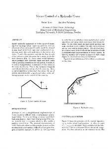
1.3 WikiLauncher rocket To inject small satellites constellation or swarms, the WikiSat team proposes to use a Rockoon, a combination between a balloon and a rocket that is inside the category of Mini-Launchers (Less than 100 kg). The rocket called WikiLauncher starts from 32 km in the stratosphere and it has at least two stages, the first stage is responsible for reach the 250 km orbit (Below the International Space Station at 350 km) and the last stage is responsible to achieve the orbital speed of 7.6 km/s. Satellites are injected in orbit only 4 hours after the balloon release. The payload mass is about 100 grams (Up to six femto-satellites) while the launcher mass restriction is less than 10 kg and less than 2 meters of length.
Figure 1 – WikiLauncher 3D model
Figure 2 – Trajectory simulation for a Disaster Management mission
21
Improvements of a vector control system for a mini-launcher based on composite materials
The trajectory is a parabolic flight, followed by a correction maneuver in the apogee, before to ignite the last stage. For this reason, the vector control system shall to correct the rocket attitude during the unstable phases of the flight. The correction maneuver consists of pointing towards the correct direction and to turn around it to provide a minimum spin to the last stage. After the jettison, this module is discarded with the previous stage and last stage engine increases the speed until the orbital speed is achieved. After then, satellites are released. Figure 2 shows the prediction of a Disaster Management mission trajectory simulation [4]. The Vector control will work only when engine is burning and during the correction maneuver.
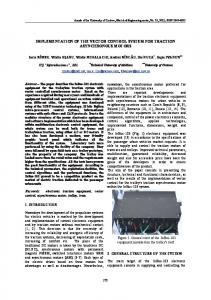
1.4 Cold gas method for the vector control system There are many ways to control the rocket vector. The most used method is by the use of a moveable nozzle. For the WikiLauncher, it represents too much complexity. For this reason, WikiSat team decided to use cold-gas and few small nozzles that will apply small forces guarantees the flight stability as proposed by Laia Navarro in [9] in page 56 (Fig. 3) and implemented by Roberto Rodríguez in [6]. The use of 4 small nozzles with a certain angle gives freedom for 4 displacements and 2 rotations that are 6 degrees of freedom.
Figure 3 – Four small nozzles have 6 DOF for the vector control
As showed in figure 4, butane is liquefied at room temperature when pressure is relatively low. This fact means that the container will be light and a large quantity of butane could be stored in liquid phase. In addition, this gas has a good specific impulse of about 80 seconds [5]. Previous designs of the vector control were studied by other students [1, 6, 7, 8]. Our objective is to reduce the mass and increase the reliability of the module to be implemented while improving the manufacturing complexity and maintainability. Figure 5 shows the baseline idea to achieve this goal. This novel idea consists of to assemble four servos in the same pack attached each other by a strap.
CHAPTER 1. WIKISAT MISSION
Figure 4 – Butane vapor pressure vs temperature
Figure 5 – Servo assembly – The baseline design
To implement the system, we will begin from a minimum number of requirements and then we will start a spiral design process to test the interface proposals [2] based on Commercial-off-the-shelf (COTS) by building prototypes. Seven prototypes were generated in this spiral. Finally, having the best prototype produced in the spiral, we will generate the system specifications and we will validate the implementation through some functional tests and hardware-in-the-loop simulations as designed by Navarro in [9] if time.
22
23
Improvements of a vector control system for a mini-launcher based on composite materials
CHAPTER 2. SYSTEM REQUIREMENTS This chapter has a list of requirements for the vector control system inside the WikiLauncher rocket.
2.1 System requirements System requirements were based on Tristancho’s femtosatellite system requirement list in [1] and the technological constrains proposed by JoveCasulleras in [8] for the mini-launcher: • SR01 The vector control system should fit into a diameter of 55 mm • SR02 The vector control system should weigh less than previous version in 136 grams for the Roberto’s prototype and 91 grams for the Brass’s prototype (See annexes for details about previous implementations) • SR03 The vector control system should have the lower number of valves • SR04 The vector control system should use a ROTHENBERGER Propan/Butan mix bottle. Content 338 grams of butano65/propano35 and 600 ml. Dry mass 125 grams. Wet mass 462 grams. Operative range from -15 to 50 ºC but can be improved through tests. Threat 7/16" type 1. • SR05 The vector control system should use the Tower Pro micro servos model MG 90S
2.2 High level requirements High level requirements were extracted from the technological constrains stated by Jove-Casulleras in [8]. • HLR01 The vector control system shall control the rocket attitude during the unstable phases of the flight • HLR02 The manufacturing of the system shall be simple and repeatable
2.3 Low level requirements Low level requirements were adapted from the technological constrains presented by Jove-Casulleras in [8]: • LLR010 The vector control system shall displace laterally the rocket in the four directions around the flight path • LLR011 The vector control system shall rotate the rocket in the flight direction and two way • LLR012 The vector control system shall be inactive during the stable phases of flight • LLR020 The vector control system shall use Commercial-off-the-shelf components
CHAPTER 2. SYSTEM REQUIREMENTS
• LLR021 The vector control system shall be easy to adjust • LLR022 The vector control system shall not require maintenance during the storage phase • LLR023 The vector control system shall have a replaceable gas container for the certification process
24
25
Improvements of a vector control system for a mini-launcher based on composite materials
CHAPTER 3. INTERFACE PROPOSALS This chapter has a set of ideas and components proposals that initially are suitable to be used in the spiral system design and they will put to the test in every design cycle. Many of these ideas or components will be discarded and only the most suitable ones, it will remain in the final design. The design starts from the use of Commercial-off-the-shelf (COTS) components available in the market as Morisca defines in [2] but extended to the hardware market.
3.1 Baseline ideas The following section has a summary list of baseline ideas that are concepts or approaches to achieve the requirements. Through the spiral system design process we will see in the next chapter, these ideas will be tested and discarded those ideas or approaches that are not useful or not good enough for the final design. • Blowtorch bottle. Butane is the best specific impulse cold-gas for vector control. We can use a blowtorch bottle because are light and commercially available. • Four valves are enough. Four nozzles placed in 45 degrees could be combined properly in order to have six degrees of freedom: Four displacements and two rotations. • Compact assembly. Four servos will be placed in a compact configuration in such a way that the four shafts are in the proper circle that corresponds to the bottle. The components will be in the center because is a compact assembly, the inertial moment will be lower than other configurations. The rocket will turn faster or easier. • Epoxy block. We propose to assemble all the valves in the same block or bed. A single cast will fix the problem; no mechanical processes are required. • Rotary valves. A drill in a cylindrical shaft could be used as a valve in order to avoid levers, tensioners and cams. We propose to use a bolt inside the block with a lateral drill that will work as rotary valve. The threat does not allow lateral displacements. • Direct drive. The servo has a range of 180 degrees. It could be enough to close and open a rotary valve. In this case we can have a direct drive from the servo to the valve shaft. We propose to use the same bolt and a nut to fix the bolt to the servo. This nut can be used for the rotation adjustment. The shorter the rotation, the faster the operation of the vector control. • Lateral drill. Rotary valves have complicated adjustments. We propose a single drill for each valve. A single drill will be enough to pass through the central collector, the bolt, the wall and also will work for the nozzle pipes.
CHAPTER 3. SYSTEM DESIGN
• Epoxy threat. The blowtorch bottle does not have a normalized threat. We propose to embed the epoxy block around the bottle threat that will fix this problem if it is stronger enough. • Epoxy insulator. The first stage rocket is closer to the vector control system. We propose to use an epoxy block to isolate the components from the heat. • Four shafts as support. Four shafts also will work as support for the servo assembly, simplifying a lot the design. • Four shafts as torque lock. Four shafts avoid the torque of each rotary valve. Extra structural components are not required while servo assembly is free to move. • Four valves as main valve. Four valves will work as a main valve if the four valves are closed and they have not leaks. Progressive control is feasible. • Bottle valve as main valve. In case of valves have some leak; we propose to use the bottle check valve punctured by a fifth servo. Pulse control can use in this case instead of progressive control. • The bottle as a cast. The block is complicate to build within same manner. We propose to use proper aluminum pipe with the same diameter of the bottle neck as a cast extension. The bottle neck inner shape and the thread will be used as the inner cast. • Plasticine as a mold. To avoid epoxy ingestion in the bottle check valve, we propose to pot a small quantity of Plasticine in the hole in such a way that will work as a central collector and it can be removed later during the adjustment process. • Countersunk head as a limit. The use of a bolt with countersunk head and some Plasticine will work as a limit for the rotation and also will give some stiffness to the rotation. We propose to fill the countersunk head of the bolt with Plasticine to avoid the epoxy lock in the bolt head. • Brass piping. The exhaust nozzles require the proper orientation. We propose small brass pipes because are easy to bend and to be placed in the single drill performed before.
3.2 Component selection In this section, a list of Commercial-off-the-shelf (COTS) components is selected to be used in the system. These components were manufactured for the domestic public and through a validation process; the ones that can resist the space environment will be selected. • TowerPro MG90S Micro servo. This is a component used in amateur aeromodels and is strong and light. This component was tested in the WikiSat Near space expedition number 3 and number 12. • ROTHENBERGER Propan/Butan mix Bottle of 660 ml. This component was designed in blowtorch for soldering or for applies flame. This component was tested in the WikiSat Near space expedition number 5 and others.
26
27
Improvements of a vector control system for a mini-launcher based on composite materials
• Palatal P4TV-129/5kg Fiberglass resin. This material was used several times in WikiSat Near space expeditions and is recovered by the NASA report [3] number SP-8108. • DIN661 M2.5 countersunk bolt. This is a metallic material and it is suitable for near space. • DIN934 M2.5 nut. This is a metallic material and it is suitable for near space. • N1.5 mm brass pipe. This is a metallic material and it is suitable for near space. • NBR O-Ring. Made of nitrile rubber that is a material used several times in WikiSat Near space expeditions. This material is recovered by the NASA report [3] number SP-8108.
29
Improvements of a vector control system for a mini-launcher based on composite materials
CHAPTER 4. SPIRAL SYSTEM DESIGN This chapter is a report of each prototype generated in the spiral system design. Each prototype will test some ideas or interface parts proposed in the chapter 3.
4.1 Prototype number 1 The prototype number 1 is a set of valve implementations in order to test how the epoxy and the steel behave before use a bottle as a mold. The concept to test is: an embedded bolt with a lateral drill will work as a rotary valve in such a way that this bolt is rotated directly by the servo. This test was performed in Friday March 1st 2013. Four aligned bolts were embedded inside a rectangular mold, screwed in the tip by a support while the countersunk head of each bolt is inside the resin in the mold. To avoid blocking the head by the resin, thermal glue was used. The case for each bolt was as follows: • First was soaked in oil as well. The head was filled with a lot of thermal glue to after allow the rotation and some stiffness. Oil will increase the tolerance between the resin and the thread but also will leak the gas pressure. • Second bolt has water wet threads. The head was filled with much thermal glue to after allow the rotation and some stiffness. There is no tolerance between the resin and the thread and there is not any gas leak but rotation will be impossible. • Third bolt has dried threads. The head was filled with some thermal glue to after allow the rotation and some stiffness. There is a small tolerance between the resin and the thread and an little gas leak but rotation will be hard to move is the initial stiff is overcome. • Fourth bolt has dried threads. The head has not any thermal glue but the head has not any hole. There is a small tolerance between the resin and the thread and a little gas leak but rotation will be too hard. Also, rotation is not possible because the bolt cannot advance in the screw movement. Referred to the lateral drill, it is difficult to ensure that the bit will go through the bolt because the opacity of the resin makes hard to see where the bolt is. Also, due to the weakness of the resin, sometimes the bit strafes or moved laterally. Once the drill is done, the bolt works as a rotary valve. Conclusions for this prototype are as follows. The idea of embedded bolt is only feasible if both, head has something elastic (Like thermal glue) and the thread is soaked in oil or at least has dried thread but never soaked in water. Next test should be focused in the bottle assembly.
CHAPTER 4. SPIRAL SYSTEM DESIGN
4.2 Prototype number 2 The prototype number 2 was done to test four valves located in square and holt by four pattern servos. Technique used will be the same as the previous prototype but an aluminum cylinder will be used as a cast. In this test, it is proposed to use the four servos, to see if they are able to rotate the screws, located within the resin. In this case nuts is thermal glue on head servos having a neutral position of 90 degrees. The screws about the bottom of the servo axis and has joined the nuts every servo axis. In the center is placed a straw filled with wax and a screw invested within the wax. It closes the straw M3 nut. In the bottom of the mold is added a piece of fiberglass to avoid cracks. The mold resin is added to reach the four nuts on the axes. The amount of resin that is above the center screw nut is a small amount and cannot guarantee good insulation. Is not easy to hold the four servos perpendicular to the table The first resin has been placed inside the mold, and then the system has got the four axes, making it difficult to put exact amount of resin. Another way is to put first axis and then add resin, which makes it very difficult to add the resin to the mold. Test of 4 valves. Thursday on March 7. Following them same steps of the previous test, this time the own servos were used as supports, giving the possibility of reuse of the servos, before some failure in the tests. In this test it proposes to verify if the servos for if alone they are capable of turning the screws, before some failure acquaintance to use the tool of torque. In order to be able to realize this test, the following points have been done: • • • •
A pipe of 30x18 mm (D25mm nominal) of aluminum impregnated in oil. Screws with a drop of thermal glue in the head. Servos located in a neutral position of 90 degrees. The screw does ceiling at the back of the axis of servo.
Once located everything, the nuts have been screwed in the respective servos. After there has been located a straw full of wax and a screw invested inside this wax, closing it with a nut of M3. Previous conditioning that has been done has been to locate a socket-pan of glass fiber at the back of the mold. Later it has been processed to filling the space with resin up to coming just before the nuts of four screws.
30
31
Improvements of a vector control system for a mini-launcher based on composite materials
With this we could have observed that there is few quantity of resin in the center so it is possible not to obtain the needed water tightness, impede to hold the servos so that they could his perpendicular dad preserves. In this process it proposed to fill with resin first and then to introduce four screws, but I reject for the difficulties of calculating the quantity of necessary resin, in case of filling after resin the difficulty it consists of avoiding the formation of bubbles inside the resin. The March 07th, 2013 as soon the epoxy was cured, it was removed from the mold easily. Wax was not easily removed and thermal glue is difficult to remove. No servos were able to turn any of the bolts; the shafts were unlocked by hand. The lack of oil was the reason of the shaft stiffness. The servo assembly and the shafts should be as centered as possible. Caution should be taken to do not fill too much, avoiding epoxy in the nuts. Thermal glue is not recommended. We recommend unscrewing the assembly from the bottle to process the part and also to certify the assembly alone. That way, the bottle could be replaced. An O-Ring seal will be mandatory for this purpose. It is very difficult to drill the shaft and to ensure that the hole is at the center when the drill is performed in epoxy. Looks like this will be an issue to overcome. In any case, valve sealing is not allowed through an epoxy-steel closure.
4.3 Prototype number 3 This prototype done in March 8th, 2013 is the same as the number 2 but using the bottle threat as the mold to cast the manifold assembly in the hope the manifold could be unscrewed. Some holes are filled by plaster. The bottle hole is protected as well to avoid the use of thermal glue and wax. Bubbles must be avoided during the filling process. An O-Ring will be required if bottle is replaceable from the manifold part. Servos are placed in a neutral position of 90º to allow a later adjustment. Oil is sprayed this time in all the mold surfaces. It is difficult to know the level of epoxy introduced during the filling; we recommend making a lateral drill in the mold extension. As soon the jammed bolts are released by the screwdriver, the servos are able to turn the shafts properly. A lateral drill was performed in every shaft. The servos were adjusted and an Arduino was programmed in order to turn separately each servo. On March 09th, 2013 a stress test is performed in order to know the wear of the valves. The servos were supplied with the minimum operating voltage at 4.4 volts. During the test, a single servo required 1.2 A to turn the valve but at the end of the test, the servo only required 1.1 A due to the wear. The idle consumption of the overall system is 90 mA. The test consisted in more than the 23,400 cycles during one day. After of then, valves have got similar leakage as the beginning. We recommend the use of inserts for the valve in order to
CHAPTER 4. SPIRAL SYSTEM DESIGN
have a metal-metal closure of the shaft. During the installation, the reduction box of the servo was destroyed when the nut was tithed. Shaft must be locked with the pliers while the nut is tithed with the wrench. On March 11th, 2013 we detected that some servos are not good even the “Q.C.” stick. Quality control is mandatory for every servo before use it.
4.4 Prototype number 4 This prototype was performed on March 11th, 2013 repeating the previous casting process. After the assembly is removed from the bottle and the assembly, the head of the screws must be reached without destroying the threat. This time, the threat was broken and the prototype must be repeated. Lateral drills were done but still an issue.
4.5 Prototype number 5 This prototype was performed on March 12th, 2013 repeating the previous casting process but adding some fiberglass inside the epoxy. A part of the seal in the bottle neck side was broken. The prototype will work but it cannot be used in a real launcher because it has a defect. Functional test was performed and each valve closes but sealing is not achieved due to the remaining screw swarf. A fifth servo is mandatory to open and close the bottle.
4.6 Prototype number 6 This prototype was performed on March 12th, 2013 and is based on the same manufacturing procedure but putting an insert in every threat. This time, the assembly was manufactures properly but one drill was now centered, even the valve works. The epoxy has little quantity of catalyst so next time mixture of the epoxy should have a bit more. Once, the valves work fine but sealing is not guaranteed so a fifth servo is mandatory. This is the best prototype we have and this is the one will be used in the specification tests.
4.7 Prototype number 7 This prototype was performed on March 12th, 2013 and is based on the same manufacturing procedure but putting a metallic embedded ring to manufacture four screwed holes. We used a M12 nut that is the proper size to fit inside the bottle neck. It was unable to make the threat in the holes so idea is discarded and anyway, a main valve is required during the storage. Sealing is not feasible.
32
33
Improvements of a vector control system for a mini-launcher based on composite materials
4.8 Summary of the spiral In this spiral cycle we have performed seven cycles generating seven prototypes in order to test different concepts until the final design is achieved.
Figure 6 – Spiral development concept (a) and Prototype implementations (b)
Figure 6(a) shows the concept of spiral development3 by creating a complete prototype each cycle. From cycle #3 to #6 was the same prototype repeated in order to improve the bottle neck casting and the drill procedure. Metallic manifold was not a good solution in cycle #7 due to the increase of weight and manufacturing cost. Figure 6(b) shows a picture for each prototype implemented in this spiral process. In addition, Table 1 summarizes main idea or interface to test in each spiral cycle, the results obtained in this implementation and conclusions/recommendations for the next iteration.
3
Source: http://teced.com/wp-content/uploads/2011/05/spiral_model.gif
CHAPTER 4. SPIRAL SYSTEM DESIGN
34
Table 1 – Prototype summary
#1
#2
#3
#4
#5
#6
#7
Idea/interface An embedded bolt with a lateral drill will work as a rotary valve
Results Conclusion - A soaked in oil threat allows To embed a the rotation but it leaks soaked in oil bolt - A dried threat will be hard to with a lateral drill is break the stiff but small leak feasible and could - A soaked in water threat is be implemented in useless, the bolt is stiff the bottle - The lateral drill is hard to do Use of a ring as a - The lack of oil provoke the Thermal glue is not cast, assembly will shaft was locked recommended and remain in the bottle - Assembly should be centered the rotary valve neck forever. Use - It is not feasible to keep the concept should be of thermal glue assembly for ever improved - Assembly can be unscrewed - Sealing is not achieved in a epoxy-steel valve Use the bottle - Carefully, the manifold could Manifold will be neck and an be unscrewed many times adjusted and extension ring as - An O-Ring will be required certified separately the mold - Bubbles must be avoided from the bottle by - It is difficult to know the level of an O-Ring. Servos epoxy when filling must be tested in - Servo’s gearbox is destroyed if order to discard the badly one shaft is not locked during tight - Stress test demonstrated that servos can work for many cycles - Some new servos are bad Improve previous - The threat is destroyed when Prototype was process to ensure reaching the head of the screw destroyed repeatability Improve previous - Stronger assy. than previous Sealing is not process adding - Bottle neck seal has a defect achieved and it is fiberglass - The valves worked fine but mandatory to use a cannot be used for a real flight fifth servo - Sealing is not achieved Use inserts to see - The assembly was Using this if valves achieve manufactures properly technology, sealing the sealing - There was a lack of catalyst is unachievable so a fifth servo is - One lateral drill was not centered but worked anyway mandatory because the metal-metal closure - Sealing is not achieved Use a metallic - Threats are not possible to be Useless idea. embedded ring manufactured Sealing is not feasible
35
Improvements of a vector control system for a mini-launcher based on composite materials
CHAPTER 5. SYSTEM MODELING This chapter contains the Computed Added Design (CAD) model, its drawings, the launcher drawings and the Computational Fluid Dynamic (CFD) simulations for the maximum angle of attack and the vector control nozzles effect.
5.1 Computed Added Design model The vector control assembly was modeled in CATIA [12]; the whole launcher was modeled as well. Figure 7(a) shows a 3D view of the vector control system (08) mounted in the butane bottle (5). The final functional prototype weighs 79 grams. The control vector system is located between the payload and the stages in such a way that, when the stage1 is empty, the center of gravity is closer to the nozzles in order to reduce the nutation effect during the apogee maneuver.
Figure 7 – Pictures and 3D model in CATIA (a) and the assembly diagram (b)
The whole vector control assembly is inside a Cover (19) not shown in the figure 7(b). Four Servos (08) are attached together by a lateral strap. The four Shafts (09) are introduced inside the epoxy Manifold (06) and adjusted by a nut (Not shown in the figure). The assembly is connected by a thread to the Bottle
CHAPTER 5. SYSTEM MODELING
36
(05) filled with Butane and sealed by an O-Ring (10). The Cold-gas (07) not shown, is released through a Needle (13) actuated by a Servo (11) and a Rod (12). The gas passes through a Piping (14) in order to make a small force or moment depending on the combination of valves selected by the Computer (15) not shown, supplied by the LiPoly Batteries (17) not shown and the Wirings (16) not shown for the sake of the clarity. For safety, there is a Jumper (18) that connects the battery supply before flight.
5.2 Drawings This section presents some sketches about the vector control and other assembly sketches, the Part List, the WikiLauncher configurations, the Payload and inter-stage assembly. Detailed drawings are located in annexes. The WikiLauncher has from top to bottom the following subsystems: • Fairing subsystem • Payload subsystem • Vector control subsystem and • Propulsion subsystem
5.2.1 Vector control assembly sketches In the figure 8 the vector control sketches are presented having the assembly main measurements.
Figure 8 – Vector control sketches
The separation arm between two opposite nozzles during rotation maneuvers is about 25.5 mm. These two opposite nozzles are injecting gas to generate a
37
Improvements of a vector control system for a mini-launcher based on composite materials
torque. The separation between two consecutive closer nozzles in Pitching maneuvers are about 23 mm. The separation between two consecutive far nozzles in Yawing maneuvers is about 64 mm. The separation between stages is about 76 mm.
5.2.2 Other assembly sketches The figure 9 shows details about the fairing subsystem with the payload measurements. The payload volume is defined as a cylinder of 62 mm of diameter and 130 mm of height. The total length of the WikiLauncher in configuration 1 is about 838.21 mm and configuration 2, its length is about 1,176.51 mm. Other WikiLauncher configurations are available in table 3.
Figure 9 – Other sketches
CHAPTER 5. SYSTEM MODELING
38
5.2.3 WikiLauncher part list Table 2 presents the part list for each subsystem and includes the totals for various combinations of light or heavy stage1 and 4 or 9 mm nozzle. The bill of materials is also included. We have considered all the WikiLauncher configurations to facilitate future flight tests. Table 2 – Part list Item 01 02 03 04 05 06 07 08 09 10 11 12 13 14 15 16 17 18 19 20 21 22 23 24 25 26 27 28 29 30 31 32 33 34 35 36 37 38 39
Subsystem Fairing 156.2 gr 4.60€ Payload
Vector Control 597.8 gr 72.85€
Propulsion (Light stage1) 1,931.9 gr 220.30€
Propulsion (Heavy stage1) 3,080.1 gr
Description 1x Tip 1x Cover 1x Strap 1x Volume 1x Bottle 1x Manifold 1x Cold gas 1x Servo assy. 4x Shaft 1x O-Ring 1x Servo5 1x Rod 1x Needle 4x Piping 4x Computer 4x Wiring 2x Battery 1x Jumper 1x Cover 1x Structure 1x Nozzle 4 mm 1x Propellant 1x Clip 1x Seal 1x Ablative 1x Igniter 1x Wiring 4x Strut 1x Cover 1x Structure 1x Nozzle 9 mm 1x Propellant 18x Bolt 1x Seal 1x Ablative 1x Igniter 1x Wiring 4x Strut 1x Cover
1. Single light stage1 (4 mm nozzle) 2. Double light stage1 (4 mm nozzle) 3. Single heavy stage1 (4 mm nozzle) 4. Single heavy stage1 (9 mm nozzle) 5. Three stage1 (4 mm nozzle)
Material Glass Aluminum Aluminum PVC Steel Fiberglass Butane PVC Steel NBR PVC PVC Steel Brass PCB Copper LiPoly PVC Fiberglass Steel Steel APCP Steel Epoxy Fiberglass Powder Copper Steel Fiberglass Steel Steel APCP Steel Epoxy Fiberglass Powder Copper Steel Fiberglass Total Total Total Total Total
Mass 26.0 gr 130.0 gr 0.2 gr 684.0 gr 200.0 gr 15.0 gr 258.0 gr 48.0 gr 3.1 gr 0.1 gr 12.0 gr 0.2 gr 0.6 gr 0.4 gr 14.8 gr 2.6 gr 41.6 gr 0.2 gr 1.2 gr 200.0 gr 22.0 gr 1,630.0 gr 0.8 gr 3.0 gr 60.0 gr 0.6 gr 2.3 gr 12.0 gr 1.2 gr 1,081.0 gr 81.0 gr 1,839.0 gr 4.0 gr 3.0 gr 60.0 gr 0.6 gr 2.3 gr 8.0 gr 1.2 gr
Cost 0.70€ 1.20€ 2.70€ 8.90€ 0.50€ 4.50€ 6.20€ 0.70€ 0.70€ 2.60€ 0.45€ 0.05€ 0.15€ 43.00€ 1.10€ 0.70€ 0.70€ 2.60€ 3.90€ 6.50€ 200.00€ 1.50€ 0.50€ 1.40€ 2.20€ 1.10€ 0.60€ 2.60€ 18.00€ 6.50€ 200.00€ 4.50€ 0.50€ 1.40€ 2.20€ 1.10€ 0.60€ 2.60€
3,369.9 gr 5,301.8 gr 4,498.1 gr 4,518.1 gr 8,361.9 gr
297.75€ 518.05€ 314.85€ 314.85€ 755.45€
39
Improvements of a vector control system for a mini-launcher based on composite materials
5.2.4 WikiLauncher configurations As it was seen, there are four main WikiLauncher configurations depending on the type or number of stages or type of nozzle used. Fifth config. is discarded.
Figure 10 – WikiLauncher with single light stage1 and 4 mm nozzle
Figure 10 shows the WikiLauncher in light configuration, the bill of materials is about 300€ and it is composed by three sections: The payload section, The vector control section and the propulsion section. The center of gravity is marked in green closer to the vector control Piping (14).
Figure 11 – WikiLauncher with double light stage1 and 4 mm nozzle
Figure 11 shows the WikiLauncher in configuration of double stage1, the bill of materials is about 520€ and it is composed by four sections:
CHAPTER 5. SYSTEM MODELING
• • • •
The payload section The vector control section The propulsion section #2 and The propulsion section #1
The center of gravity is marked in green closer and is located in the propulsion section #2 at the beginning of flight and closer to the vector control Piping (14) at the end of burn.
Figure 12 – WikiLauncher with single heavy stage1 and 4 mm (a) and 9 mm nozzle (b)
Figure 12 shows the WikiLauncher in configuration of heavy stage1 for a 4 mm nozzle 12(a) and 9 mm nozzle 12(b), the bill of materials is about 320€ and it is composed by three sections:
40
41
Improvements of a vector control system for a mini-launcher based on composite materials
• The payload section • The vector control section and • The propulsion section like the light configuration The center of gravity is marked in green in every case, closer to the end of the propulsion section but closer to the vector control Piping (14) before ignition. Table 3 presents a summary of some WikiLauncher configurations, the total length, the center of gravity, the total mass and the bill of materials cost. Table 3 – WikiLauncher configuration summary WikiLauncher Configuration 1. Single light stage1 (4 mm) 2. Double light stage1 (4 mm) 3. Single heavy stage1 (4 mm) 4. Single heavy stage1 (9 mm) 5. Three stage1 (4 mm)
Length 838.21 mm 1,176.51 mm 845.85 mm 851.06 mm 1,517.51 mm
4
CG 243 461 341 339 663
5
Gap 270 348 -
Mass 3,369.9 gr 5,301.8 gr 4,498.1 gr 4,518.1 gr 8,361.9 gr
Cost 297.75€ 518.05€ 314.85€ 314.85€ 755.45€
5.2.5 Payload and inter-stage assembly The payload (04) is defined as a volume of 500 cc inside a cylinder of Ø65.5x154.0 mm and a mass of 684 grams. Average payload density is 1.368 g/cm3. Obviously, the inertial matrix will change respect to the computed trajectory used in this work when a new payload is introduced but the change is not significant. The payload is protected by the Fairing Subsystem composed by a Tip (01) and the Cover (02). This fairing is attached to the Vector control subsystem bottle (05) through a thin strap (03).
Figure 13 – Attachment system between sections
Each stage is attached through 4x M3 bolts or struts (28) or (38) that support the thrust when engine is burning as presented in figure 13. The jettison system breaks these 4 bolts during the ignition because they are designed to work in compression and released in traction. When next engine starts, the bolts releases with a minimum thrust and ignition subsystem wirings are also burned. Vector control (08) will compensate jettison asymmetries. Everything is managed by the MCU Computer (15) and connected by Wires (27) but control is satellite’s responsibility. The MCU has two power supply batteries (17) and a 4 5
Center of Gravity measured from the end of the nozzle in mm The Center of Gravity displacement when propellant and cold gas is over in mm
CHAPTER 5. SYSTEM MODELING
safety Jumper (18) marked as “REMOVE BEFORE FLIGHT”. One battery (3.3 V) feeds the MCU the other (7.2 V) feeds the servos and igniters (26) and (36).
5.3 Computational Fluid Dynamics simulations Few Computational Fluid Dynamic (CFD) simulations [10] were run in order to see the shockwaves at various angles of attack, as well as the vector control nozzle flow effects. The simulations have 262,000 fluid cells of mesh and a supersonic solver was used in the CFD module in Solid Works; annexes contain details about these simulations. The maximum allowed angle of attack at 8 Mach is 4 degrees as can be seen in figure 14(a), this is the faster speed that stage1 has got in the trajectory simulation as presented in section 6.3 achieved at 104.6 km of altitude.
Figure 14 – CFD simulations – Angle of attack at 8 Mach 8 in near space (a) and nozzle configurations to generate the launcher Pitch, Yaw and Roll (b)
42
43
Improvements of a vector control system for a mini-launcher based on composite materials
The previous CFD simulation seen in the figure 14(b) was the flow of the vector control nozzles in three cases: Pitch, Yaw and Roll. In the Pitch configuration, two consecutive closer nozzles were used in order to generate a force and the launcher pitch rotation. In the Yaw configuration, two consecutive far nozzles were used to generate a force and the launcher yaw rotation. In the Roll configuration, two opposite nozzles were used to provoke a rotation around the launcher Y axis. Simulation was run in the same conditions as the previous CFD figure 14(a). In this case a flow of 2 g/s of butane and 9 atmospheres were applied at each active nozzle. CFD simulations should be compared with real experiments.
45
Improvements of a vector control system for a mini-launcher based on composite materials
CHAPTER 6. SYSTEM IMPLEMENTATION This chapter contains the manufacturing process, the system performances, an example of trajectory and a static flight test.
6.1 Manufacturing process The final prototype where functional tests are performed is based on the idea of to use the butane bottle neck as a cast for composite material based on epoxy (Styrene) as matrix and fiberglass as reinforcement. Inside, before curing, four bolts with inserts attached to four pattern servos will be introduced in the correct position. The threats of each bolt will be oiled in order to avoid the epoxy is attached to the threat. The mold is easy to dismount after curing. Four lateral drills will be performed to the block assembly but without the bolts. Later, bolts will be positioned with the final servos and locked through a nut in each bolt. These servos will be adjusted to a neutral position then a mark will be performed to the bolts by the bit and each bolt head will be marked to show the location of this mark. One by one, each bolt will be drilled. Threat will be rebuilt avoiding dirty in the threat. That way, it is easier to drill in the middle of the bolt; otherwise, the bolt could be broken or will not be aligned properly. Never should be removed more than one bolt at the time in order to do not lose the adjustment. Servos do not have a support and relative position is granted by the four bolts.
6.2 System performances The WikiLauncher in configuration of single light stage1 (Config. 1) has the so called Gimbal Lock6 problem. The figure 15 shows how the center of gravity is very close to the nozzles and displaced 270 mm when stage1 is burned. The WikiLauncher is aerodynamically unstable but thanks to the flight is in the weak atmosphere, the aerodynamic forces will be small. The arm between the forces and nozzles are small and becomes smaller when stage1 burns due to the type of propellant is an End Burner. During the first moment of flight, the launcher has to make a turn in Pitch of few degrees so it is mandatory to have a larger vector control arm changing the mass distribution or adding ballast. In the Correction maneuver at the apogee, the center of gravity should be as closer as possible to the nozzles in order to reduce the effects of nutation when the payload is spinning.
6
http://en.wikipedia.org/wiki/Gimbal_lock
CHAPTER 6. SYSTEM IMPLEMENTATION
Figure 15 – Gimbal Lock problem of the Vector Control
Functional tests are performed to ensure that servos are able to turn the bolts opening and closing the rotary valve. Overall consumption should not be more than 400 mA in every maneuvering. The servo current was 1.1 mA at 4.5 V. Pressure should be kept in closed position and released in open position. The cold gas bottle has a total of 258 grams of gas that can work for 60 seconds. A flow of 2 g/s of cold gas at 9 atmospheres were assumed at each active nozzle. Estimated total flow is 258 g / 60 s = 4.3 g/s. The fifth servo is able to open and close the manifold pressure in 50 ms that means 20 maneuvers per second and an average total of 1,200 cycles. The servos were tested for more than 23,000 cycles working properly.
6.3 Example of trajectory In this section, the implemented prototype is validated through some functional tests and hardware-in-the-loop simulations as designed by Navarro in [9]. The launcher lifts-off from a balloon at 32 km of altitude reaching the orbital altitude. Figure 2 from chapter 1 showed the trajectory simulation that has followed the launcher. The rocket attitude is controlled by the vector control and depicted in bold white color. The predicted trajectory that stage1 will follow was marked in thin pink color. The vector control MCU is connected through an UART interface to a serial port in the computer where the simulator closes the hardware-in-theloop. During the simulation some specifications are tested such as the reaction time and the inertial effects over the roll control (That are rotations) and over Pitch and Yaw controls (that are lateral displacements). The simulator requires the inertial matrix which changes depending on the launcher configuration (See table 3). The reference systems are many and we propose to use a standard
46
47
Improvements of a vector control system for a mini-launcher based on composite materials
[11] like the aeronautical one7. Anyway a summary of reference systems and its application used in this work is presented in the annexes. Following subsections will show the center of gravity location respect to the end of the nozzle and its inertial matrix for each case seen in section 5.2.4 where Y axis is the flight direction. Fifth configuration is not studied in this work.
6.3.1 Config1. Inertial matrix with single light stage1 and 4 mm nozzle The case for the WikiLauncher in configuration of single light stage1 has a total mass of 3,370 grams. This case is composed by the payload section, the vector control section and a light stage1 with a 4 mm nozzle. The inertial matrix in kg·m2 respect to the exhaust nozzle is showed in (5.1) marked as I1 and the center of gravity is located at I CG1 = (0 297 0 ) mm respect to the thrust vector.
0.659 0.071
0
I1 = 0.071 0.009 0 0 0 0.666
(5.1)
The inertial matrix in kg·m2 respect to the exhaust nozzle when dry (First stage burned) is showed in (5.2) marked as I 1Dry and the center of gravity is displaced 270 mm forward. It is located at I CG1Dry = (0 567 0 ) mm respect to nozzle exit.
0.590 0.063
0
I1Dry = 0.063 0.008 0 0 0 0.597
(5.2)
6.3.2 Config2. Inertial matrix with double light stage1 and 4 mm nozzle The case for the WikiLauncher in configuration of double light stage1 has a total mass of 5,302 grams. This case is composed by the payload section, the vector control section and two light stage1 with a 4 mm nozzle in both stages. The inertial matrix in kg·m2 respect to the exhaust nozzle is showed in (5.3) marked as I 2 where the center of gravity is located at I CG 2 = (0 461 0 ) mm respect to the nozzle exit. 1.931 0.207 0
I 2 = 0.207 0.025 0 (5.3) 0 0 1.953 The center of gravity is displaced 270 mm forward when first engine is burned. It is located at I CG 2 Dry = (0 731 0 ) mm respect to the nozzle exit. The displacement when both engines are empty is 384 mm but in this case, engine 1 was jettisoned and the reference point has changed.
7
http://en.wikipedia.org/wiki/Flight_dynamics_(fixed-wing_aircraft)
CHAPTER 6. SYSTEM IMPLEMENTATION
48
6.3.3 Config3. Inertial matrix with heavy stage1 and 4 mm nozzle The case for the WikiLauncher in configuration of single heavy stage1 and 4 mm nozzle has a total mass of 4,498 grams. This case is composed by the payload section, the vector control section and a heavy stage1 with a 4 mm nozzle. The inertial in kg·m2 respect to the exhaust nozzle is showed in (5.4) marked as I 3 where the center of gravity is located at I CG 3 = (0 441 0 ) mm .
0.731 0.078
0
I 3 = 0.078 0.012 0 0 0 0.740
(5.4)
6.3.4 Config4. Inertial matrix with heavy stage1 and 9 mm nozzle The case for the WikiLauncher in configuration of single heavy stage1 and 9 mm nozzle has a total mass of 4,518 grams. This case is composed by the payload section, the vector control section and a heavy stage1 with a 9 mm nozzle. The inertial matrix in kg·m2 respect to the exhaust nozzle is showed in (5.5) marked as I 4 where the center of gravity is located at I CG 4 = (0 339 0 ) mm .
0.747 0.080
0
I 4 = 0.080 0.012 0 0 0 0.755
(5.5)
6.4 Static flight test This section proposes a static flight test based on a hardware-in-the-loop experiment. These tests are required before a real flight.
6.4.1 Hardware-in-the-loop experiment setup Rodriguez-Miguel in [6] studied a similar vector control implementation, studying the proper control loop required for this purpose, but never tested in a WikiLauncher. For this reason, the launcher was placed in the gimbal, providing 2 DoF; Yaw is locked at this time. Arduino computer keeps the zenith, orienting the Pitch rotation normal to North seen from our laboratory location (Figure 16).
49
Improvements of a vector control system for a mini-launcher based on composite materials
Figure 16 – WikiLauncher gimbal
The Link panel was configured in order to communicate with the Arduino computer in the launcher as showed in figure 17. The external link mode is set to “Control” mode. The link port is set to the available COM port at “4800 bauds” and settings “8,1,N,N”. The hardware-in-the-loop option is activated by selecting “Launch Trajectory”: Arduino controls the rocket when running the trajectory simulation. Attitude control is done by changing Pitch, Roll and Yaw angles. In this case, Yaw is locked to 0º. Pitch is kept at 90º while Roll is set at 90º.
Figure 17 – Link panel configuration – Moon2.0 simulator
The Arduino board has 11 DoF (See annexes for details about the Arduino specifications) so it was easy to implement the algorithm. It used the magnetic compass to provide the Roll angle kept at 90º, normal to the ground surface at this point; valves are injecting gas in a configuration showed in figure 18. The Pitch is set at 90º, also normal to the ground surface at this point. The valves are injecting gas in a configuration showed in figure 19. Hence, the Yaw correction since is locket to 0º, no corrections are required in this sense but they can be tested orienting the gimbal support pointing the Yaw rotation normal to the North.
CHAPTER 6. SYSTEM IMPLEMENTATION
Figure 18 – Static test. A torque for rotations in Roll
Figure 19 – Static test. A moment for rotations in Pitch
6.4.2 Results Due to the lack of time, we were not able to implement the radio-link between the launcher and the simulator in order to perform the hardware-in-the-loop before we printed this work. Any case, in the early tests, we have observed that the liquefied butane changes the center of gravity a little. The vector control algorithm should take into account this fact in a real flight. It was calculated that the WikiLauncher center of gravity in configuration 1 is displaced 270 mm forward when stage1 is burned; crossing the nozzles and generating a gimbal-lock situation.
50
51
Improvements of a vector control system for a mini-launcher based on composite materials
CHAPTER 7. CONCLUSIONS This chapter presents the general conclusions, the system conclusions and the environmental impact study.
7.1 General conclusions • The main objective was achieved: To build a prototype (Called the system) of a simplex vector control device for the WikiLauncher based on the idea of to use the butane bottle neck as a cast for composite material (Styrene). • The achieved implementation is better than the previous in terms of mass and simplicity. • Secondary objective was not achieved: A real flight to test the performances of the system. The difficulty of to perform a real flight is huge; some static tests were done instead.
7.2 System conclusions • System requirements were achieved. Mass assembly is 85 grams while the previous prototype was 91 grams. The system fits in a diameter of 55 mm. • The spiral system design demonstrated that works fine to develop a functional prototype in a few weeks. • High level requirements were achieved. Rotary valve concept does not guarantee the sealing. A main valve is required that will work for pulse control instead of progressive control. • Computational Fluid Dynamic showed that the maximum allowed angle of attack at 8 Mach is 4 degrees before the shockwave touches the tail and creates instability. • The WikiLauncher in configuration of light stage1 (Config. 1) has a problem with the center of gravity that is too close to the nozzles. The arm to create a moment in Pitch and Yaw is small and there is not enough moment to make sure the vector control is stable. We propose to change the Butane bottle for a smaller one in order to displace the center of gravity. • The low-cost manufacturing process based on to use the bottle neck as the cast, performing four lateral drills for the four parallel shafts looks like worked fine but a fifth servo is mandatory due to the rotary valve cannot achieve the sealing. • During the early static flight test, we have observed that the liquefied butane changes the center of gravity a little. The vector control algorithm should take into account this fact. • Cold gas quantity should be tested in a real flight.
CHAPTER 7. CONCLUSIONS
7.3 Future work Even the Computational Flow Dynamic simulations were performed with Solid Works, the use of ANSYS 13 is recommended because it will produce better and more detailed results like dynamic analysis, modal study and harmonic study. Due to the lack of time, the hardware-on-the-loop test should be improved in order to complete the static test. A real flight to test the vector control subsystem is mandatory to validate the static test.
7.4 Environmental impact The use of solid propellant is nasty but using this type of launcher based on a rockoon is a significant reduction of contamination if a conventional launch provider is used. Reusable orbits at a very Low Earth Orbit are an important reduction of space Junk. In any moment safety regulations were observed by any WikiSat team member. The author proposes a local reforest action consisting in the tree plantation of few trees in the program8 “Bosque de los Amigos de la UPC en Cornellà de Llobregat”.
8
http://www.upc.edu/saladepremsa/al-dia/mes-noticies/2011/se-inaugura-el-bosque-de-los-amigos-de-la-upc-en-cornella-de-llobregat
52
53
Improvements of a vector control system for a mini-launcher based on composite materials
CHAPTER 8. BIBLIOGRAFÍA [1] Tristancho, J., Implementation of a femto-satellite and a minilauncher for the N-Prize, UPCommons, Vol., No., pp., 2010, UPC http://hdl.handle.net/2099.1/9652 [2] Morisco, M., Reaman, C., Parra A., Basili, V., Kraft, S., Condon, S., Investigating and Improving a COTS-Based Software Development Process, 22nd International Conference on Software Engineering, Limerick, Ireland, Vol., No., pp., June 2000 http://www.cs.umd.edu/~basili/publications/proceedings/P89.pdf [3] Advanced composite structures, NASA SPACE VEHICLE DESIGN CRITERIA (Structures), NASA Langley Research Center (Hampton, VA, United States), Vol., No., pp. 107, August, 1974, NASA Report SP-8108 [4] Tristancho, J., Gutierrez-Cabello, J.; Simplified Femto-satellite Operations for Disaster Management Missions, UPCommons, Vol., No., pp., October 2012, UPC http://upcommons.upc.edu/handle/2117/18494 [5] Llorens-Aymerich, I., Disseny d'un motor de gas fred per a aplicacions en petits satèl·lits, UPCommons, Vol., No., pp., February 2013, UPC https://mitra.upc.es/SIA/PFC_PUBLICA.DADES_PFC?w_codipfc=7121 [6] Rodriguez-Miguel, R., Study of a nozzle vector control for a low cost mini-launcher, UPCommons, Vol., No., pp., July 2013, UPC http://hdl.handle.net/2099.1/12521
[7] Ruizhi, Y., Study and implementation of the stability and control system of a mini-launcher, UPCommons, Vol., No., pp., July 2013, UPC http://hdl.handle.net/2099.1/12940 [8] Jove-Casulleras, R. , Technical constraints for a low cost femtosatellite launcher. A: 49th AIAA Aerospace Sciences Meeting including the New Horizons Forum and Aerospace Exposition. Seattle, Vol., No., pp., 2011 http://www.aric.or.kr/treatise/journal/content.asp?idx=136525 [9] Laia Navarro, Use of hardware-on-the-loop to test missions for a low cost mini-launcher, UPCommons, Vol., No., pp., 2011, UPC http://upcommons.upc.edu/pfc/bitstream/2099.1/11754/7/TFC_LaiaNavarro_me moria_v2.0.pdf [10] Anderson, J.D. Computational Fluid Dynamics, McGraw-Hill, Inc., New York, 1995 http://astronomy.nju.edu.cn/~chenpf/tmp/CFD.pdf
CHAPTER 8. BIBLIOGRAPHY
54
[11] Carmona, A., Aerodinámica y actuaciones del avión, 11ª Edición 2ª reimpresión, Thomson Paraninfo, Madrid, 2002 http://es.scribd.com/doc/95349981/Aerodinamica-y-Actuaciones-del-AvionCarmona
WEB REFERENCES [12] CATIA Documentation http://www.3ds.com/es/support/downloaddocumentation/resource-library/ (January 2013)
ANEXES
TÍTOL DEL TFC: Millores en un sistema de control vectorial per a una mini-llançadora basat en materials compostos TITULACIÓ: Enginyeria Tècnica Aeronàutica, especialitat Aeronavegació AUTOR: Alí Beizaee DIRECTOR: Joshua Tristancho Martínez DATA: 26 de Juny de 2013
57
Improvements of a vector control system for a mini-launcher based on composite materials
Annexes. Reference systems and its applications
Reference system of the Arduino installed in the WikiSat (a) and in the WikiLauncher (b)
Reference system in Aeronautics. Source: Wikipedia (a) and Moon2.0 simulator (b)
Reference system in CATIA (a) and Solid Works for CFDs (b)
ANNEXES
Annexes. CFD simulation Supersonic solver. Alpha=0º WikiLauncher configuration: Config1 Flight phase: When engine is turned off Atmosphere conditions Temp=247.85K Pressure=14.64 mPa g=9.485 m/s2 Altitude=104.619 km Kinetics DeltaV: 3,604 m/s Launcher total velocity: 2860 m/s (Mach 8.3) Angle of attack: 0º Drag: 4.8 mm/s2 (dry mass=400 grams; Fdrag=0.00192 Nw) Max G during the burn: 11g Flight time: 1m 16s Nozzle modeling Temp=970K Pressure: 10,129.5 Pa mass flow= 0.0217 kg/s Area = D8mm (50.3 mm2)
CFD Fluid cells: 262,124 (Mark 3) Iterations: 1,000 CPU time: >1,000 seconds Parameters: Pressure, Mach Number and Temperature
58
59
Improvements of a vector control system for a mini-launcher based on composite materials
Alpha=0º
ANNEXES
Annexes. CFD simulation Supersonic solver. Alpha=5º WikiLauncher configuration: Config1 Moment of the flight: When engine is turned off Atmosphere conditions Temp=247.85K Pressure=14.64 mPa g=9.485 m/s2 Altitude=104.619 km Kinetics DeltaV: 3604 m/s Launcher total velocity: 2,860 m/s (Mach 8.3) Angle of attack: 5º Vx=2,849 m/s Vy=249 m/s Max G during the burn: 11g Flight time: 1m 16s Nozzle modeling Temp=970K Pressure: 10,129.5 Pa mass flow= 0.0217 kg/s Area = D8mm (50.3 mm2) CFD Fluid cells: 262,124 (Mark 3) Iterations: 1,000 CPU time: >1,000 seconds
60
61
Improvements of a vector control system for a mini-launcher based on composite materials
Alpha=5º
ANNEXES
Annexes. CFD simulation Supersonic solver. Alpha=10º WikiLauncher configuration: Config1 Moment of the flight: When engine is turned off Atmosphere conditions Temp=247.85K Pressure=14.64 mPa g=9.485 m/s2 Altitude=104.619 km Kinetics DeltaV: 3,604 m/s Launcher total velocity: 2,860 m/s (Mach 8.3) Angle of attack: 10º Vx=2,817 m/s Vy=497 m/s Max G during the burn: 11g Flight time: 1m 16s Nozzle modeling Temp=970K Pressure: 10,129.5 Pa mass flow= 0.0217 kg/s Area = D8mm (50.3 mm2) CFD Fluid cells: 262,124 (Mark 3) Iterations: 1,000 CPU time: >1,000 seconds
62
63
Improvements of a vector control system for a mini-launcher based on composite materials
Alpha=10º
ANNEXES
Annexes. CFD simulation. Vector control flow. Pitch Estimated total flow 258 g / 60 s = 4.3 g/s Each nozzle will flow at 2 g/s Pressure: 7 Atm = 709,275 Pa Temperature: 293.2 K Nozzle configuration: Two consecutive closer nozzles Distance between nozzles: 21.9 mm WikiLauncher effect: Launcher pitch rotation CFD Fluid cells: 262,124 (Mark 3) Iterations: >100 CPU time: >1,000 seconds
64
65
Improvements of a vector control system for a mini-launcher based on composite materials
Annexes. CFD simulation. Vector control flow. Yaw Estimated total flow 258 g / 60 s = 4.3 g/s Each nozzle will flow at 2 g/s Pressure: 7 Atm = 709,275 Pa Temperature: 293.2 K Nozzle configuration: Two consecutive far nozzles Distance between nozzles: 63.8 mm WikiLauncher effect: Launcher Yaw rotation CFD Fluid cells: 262,124 (Mark 3) Iterations: >100 CPU time: >1,000 seconds
ANNEXES
Annexes. CFD simulation. Vector control flow. Roll Estimated total flow 258 g / 60 s = 4.3 g/s Each nozzle will flow at 2 g/s Pressure: 7 Atm = 709,275 Pa Temperature: 293.2 K Nozzle configuration: Two alternative nozzles Nozzle arm: 12.7 mm respect to the center of gravity WikiLauncher effect: Launcher Roll rotation around the flight direction. Also it is the spinner angular rotation vector provided to the last stage. CFD Fluid cells: 262,124 (Mark 3) Iterations: >100 CPU time: >1,000 seconds
66
67
Improvements of a vector control system for a mini-launcher based on composite materials
Annexes. WikiLauncher configuration 1 Center of Gravity (297 mm) in Configuration 1 Wet. Mass 3.233 kg
Center of Gravity (567 mm) in Configuration 1 Dry. Mass 1.633 kg
ANNEXES
68
Annexes. WikiLauncher configuration 2 Center of Gravity (461 mm) in Configuration 2 Wet. Mass 5.084 kg
69
Improvements of a vector control system for a mini-launcher based on composite materials
Annexes. WikiLauncher configuration 3 Center of Gravity (341 mm) in Configuration 3 Wet. Mass 4.381 kg
ANNEXES
70
Annexes. WikiLauncher configuration 4 Center of Gravity (339 mm) in Configuration 4 Wet. Mass 4.417 kg
71
Improvements of a vector control system for a mini-launcher based on composite materials
Annexes. Trajectory simulation The WikiSat team proposes the use of a Rockoon that is a combination between a balloon and a rocket. The rocket is called WikiLauncher. This launcher starts from 32 km in the stratosphere bursting the balloon. The launcher should have at least two stages depending on the payload mass. The first stage is responsible of reaching a 250 km orbit (Below the International Space Station that has a 350 km altitude orbit above the Sea Level). The last stage is responsible to achieve the orbital speed of 7.6 km/s. Depending on the WikiLauncher configuration it can have more than two stages but all of them except for the last stage will be used to achieve the apogee. Satellites are injected in orbit only 4 hours after the balloon release. The payload mass is about 100 grams (Up to six femto-satellites) while the launcher mass is less than 10 kg and less than 2 meters of length.
The trajectory is mainly a parabolic flight. After of them, there is a correction maneuver before the apogee. A spinning maneuver is also required before to ignite the last stage. For this reason, the vector control subsystem should be located before the last stage. The vector control system shall to correct the rocket attitude during the unstable phases of the flight. The correction maneuver consists of to point towards the correct direction and to turn around it to provide a minimum spin to the last stage. After the last jettison, this module should be discarded with the previous stage. The last stage increases the speed until the orbital velocity is achieved. After then, satellites can be released. The previous figure was extracted from a Disaster Management mission trajectory simulation presented by Tristancho in [4]. The Vector control will work only when engine is burning and during the correction maneuver. The rest of the time is in idle. The Link panel (F9) of the Moon2.0 simulator was configured in order to communicate with the Arduino computer in the launcher as showed in the following figure. The external link mode is set to “Control” mode. The link port is
ANNEXES
set to the available COM (COM1 in the example) port at “4800 bauds” and settings “8,1,N,N”. The hardware-in-the-loop option is activated selecting the option “Launch Trajectory” which means that, when running the trajectory simulation, the Arduino will control the Rocket. The attitude control is done by changing the Pitch, Roll and Yaw angles. In this case, Yaw is locked to 0º and Pitch is kept at 90º while Roll is maintained at 90º as well.
72
73
Improvements of a vector control system for a mini-launcher based on composite materials
Annexes. Roberto’s vector control implementation Previous implementation mass was 136 grams for the Roberto’s prototype [6]. This version presented too much complexity for a Low-cost application.
ANNEXES
74
Annexes. Brass implementation Previous implementation mass was 91 grams for the Brass’s prototype based on the idea of a butane bottle but too heavy and expensive for a low-cost application.
75
Improvements of a vector control system for a mini-launcher based on composite materials
Annexes. Ali’s implementation The final implementation is 85 grams for the composite material based manifold. This mass includes the Arduino computer and the LiPoly batteries. This version was simplified to the maximum using micro-valves based on the rotary concept.
ANNEXES
76
Annexes. WikiLauncher drawings DRAWINGS SUMMARY 1x WikiLauncher configuration 1x Payload subsystem 7x Vector control subsystem 5x Propulsion subsystem
77
Improvements of a vector control system for a mini-launcher based on composite materials
Annexes. WikiLauncher configurations summary
ANNEXES
78
Annexes. Payload subsystem drawings
79
Improvements of a vector control system for a mini-launcher based on composite materials
Annexes. Vector control subsystem drawings
ANNEXES
80
81
Improvements of a vector control system for a mini-launcher based on composite materials
ANNEXES
82
83
Improvements of a vector control system for a mini-launcher based on composite materials
ANNEXES
84
85
Improvements of a vector control system for a mini-launcher based on composite materials
ANNEXES
86
Annexes. Propulsion subsystem drawings
87
Improvements of a vector control system for a mini-launcher based on composite materials
ANNEXES
88
89
Improvements of a vector control system for a mini-launcher based on composite materials
ANNEXES
90