Proceedings of the World Congress on Engineering 2008 Vol I WCE 2008, July 2 - 4, 2008, London, U.K.
Improvements on Face Detection in Line-Drawings A. Piquer, Member, IAENG
Abstract—Detection of faces in line drawings previous to 3D Reconstruction process is essential for a correct result. In this article a complete state of art about detection of faces in the 3D reconstruction area is given. Then some improvements over the best algorithm are described, and some examples of the results of our approach are shown. Index Terms— 3D Reconstruction, Faces detection, Line Drawings, Polyhedron.
I. INTRODUCTION During the last decade sketching-based geometric modellers have become in one of the main work lines to obtain easy to use computer aided design interfaces and providing a tool for strengthening designer’s creativity [1]. 3D Reconstruction of line drawings is a computer graphics subject that studies artificial perception of three-dimensional models held in two-dimensional drawings. A wide analysis of the studies’ evolution can be found in Company et al. [2]. In this article we assume that the initial line drawing is a sketch of a single view of a model projected in axonometric perspective represented like a wire-frame that is with all their edges and contours visible. One of the main problems in 3D reconstruction of polyhedral objects from 2D line-drawings is the early face detection. The faces of a 3D model depicted in a sketch or line-drawing is valuable information. Sometimes this information can be interesting for improving the efficiency of 3D reconstruction process and also it can be essential for some reconstruction strategies. In any case, this is hard information to obtain. This is a complex problem because the faces detection is useful in the 3D reconstruction process only if they are detected in the image, - before the reconstruction process, and then without any information about the model depth. Thereby, an approach based only on projective geometry is insufficient. At this moment, the most effective approaches use heuristic rules and they formulate the problem based on graph theory [3]. Then, the faces detection is reduced to determine all circuits in the graph fulfil some conditions. Similarity between a graph and a line drawing output of the Manuscript received March 22, 2008. This work was supported in part by the Spanish Ministry of Science and Education and the European Union under Project DPI2007-66755-C02-01, titled “CUESKETCH: Reconocimiento de Bocetos de Ideación basado en Multi-Agentes”. Piquer, A. is with the Mechanical Engineering and Construction Department, Universitat Jaume I, 12071 Castellón –Spain. (corresponding author: 0034-964-728122; fax: 0034-964-728106; e-mail:
[email protected]). URL: http://www.regeo.uji.es.
ISBN:978-988-98671-9-5
projection of a wire-frame model or B-Rep model is obvious: Even similar nomenclature is used in both: edges, vertices… II. PREVIOUS WORKS Methods for detecting faces in 2D line drawings have changed from geometric basis to more topological approaches. Labelling of line drawings methods can be understood as precedent in faces detection, from Huffman [4] and Clowes [5], to Varley and Martín [6], [7]. At this moment, methods for detecting faces in line-drawings can be classified in two groups. Both of them analogise line drawings with graphs. The thesis of Roberts [8] was the first work about perception of 3D objects from line drawings, and in them a whole chapter was about “polygon recognition”. Roberts’s method classifies edges connecting in a vertex depending on their angle with a reference direction. His method was used for identifying faces in drawings without hidden lines, because he assumed input depicted opaque models (also called natural drawings [9]). In 1992 Leclerc y Fischler [10] shown their algorithm based on heuristic assumptions. This method offers good appreciations about how human beings perceive plane figures, but some errors in their results have been detected. Furthermore, a high computational cost is registered that make the method slow. Lipson and Shpitalni studies [11] define two different methods. One method detects faces of 2-manifold polyhedron of genus zero, and another general method that firstly detects a group of candidate faces and after eliminates false faces. In their method for detecting faces in 2-manifold polyhedron of genus zero, the graph is embedding into a planar graph and the faces of the graph embedded are calculated. This method is theoretically good and simple, but it presents serious problems computationally. Furthermore, its validity is limited to 2-manifold polyhedron of genus zero. The second method of Lipson and Shpitalni is based on topological rules and graph theory but offers excessive times of calculus. This approach was implemented and improved by Conesa [12]. But he proves that this method offered some mistakes and a too high cost of time, because it has too much rules and comparative conditions that makes the method too slowly even in easy models. In more complex models times were unacceptable for interactive software. Courter and Brewer method [13] is the most efficient approach for detecting faces in eulerian polyhedron. Their proposal is merely topologic. It is based on the detection of fundamental circuits and their combination. The criterion for the combination is what topological properties a well-defined
WCE 2008
Proceedings of the World Congress on Engineering 2008 Vol I WCE 2008, July 2 - 4, 2008, London, U.K.
3D model should have. The method has its basis in the method of Ganter y Uicker [14]. Fundamental circuits are calculated from the spanning tree by BFS (Breath-First Search) and the Adjacency Matrix of Paton [15]. Once the fundamental circuits are obtained making use of a set of operations called the Symmetric Difference combines them. And the criteria applied to combine fundamental circuits are basic criteria from Graph Theory [16]. Courter and Brewer algorithm also includes a post-process of some irregularities. In spite of this algorithm is old, it has such conceptual and computational simplicity that it is more effective than the previous studied before in the bibliography. But this algorithm only accepts 2-manifold, and the method described by Lipson and Shpitalni can accept other kind of drawings.
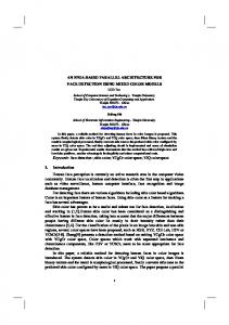
Fig. 1. Detection of faces with Courter and Brewer algorithm: 55 edges, 35 vertices and 22 faces.
III. OUR APPROACH The Courter and Brewer algorithm obtains good results in most of drawings tested, but in 2-connected graphs not always offer so good behaviour. If a 3-connected graph is converted in a planar graph, it has only one possible configuration. But 2-connected graphs can adopt two different solution (see Fig. 2), and then two possible configurations and different results from the face detection process. Methods from Graph Theory for detecting if a graph is 2-connected are reliable [17], [18] but are hardly to implement. Our method calculates faces applying Courter ad Brewer algorithm in our programme REFER, and with the circuits found (already reduced) we start the next method. A. Cutting faces detection Results obtained using Courter and Brewer method in 2-connected graphs can offer correct faces perceptually or those equivalents topologically but with a wrong perceptual
(a) Fig. 2.
meaning. With the aim of detecting these “crossed faces” we develop a strategy based on looking for:
That faces (or circuits) with more than one vertex in common belonging to different edges. In fact, any two adjacent faces have one edge in common (two vertices). But a couple of candidate faces to be false faces in a 2-connected graph must share at least another vertex in common. This other vertex can belong to another edge shared by both faces (it is the most common situation), or not. Then these two faces with all those vertices in common are the potential false faces. For example, Fig. 4 and Fig. 5 show different detection of faces of the line drawing in Fig. 3. In this line-drawing the faces number 4 and 6 in Fig. 4 have in common the edge d and the vertex 0 too. Then the set of cutting vertices in the graph is the vertex 0 and one of the d edge’s vertices (number 4 or 5). Summarizing, the first aim is to find a couple of faces sharing two vertices belonging to different edges. We set the next process for finding potential false faces: 1) A matrix CV is calculated with a row for each face calculated and a column for each vertex in the graph. Its elements (i, j) have value 1 when the face i holds the vertex j and 0 in other case. 2) A matrix R is made multiplying CV matrix by itself. Then R is a square matrix which size is the number of faces, and its elements are an integer number corresponding with number of vertices in common between faces. The diagonal elements of R have the number of vertices in each face. 3) A Checking Matrix is made mathematically from R-2xZ, where Z is the edge-interaction matrix in Courter and Brewer method. 4) The value of elements in Matrix R is checked. With the exception of diagonal elements, every element with a value bigger than number two represents a couple of candidate false faces 5) Every element with a value no-null in the Checking Matrix also needs to be studied when the same element in matrix R is a number upper than one. Both conditions must be required at once, because both faces can have only one vertex in common and it does not imply a 2-connected graph.
(b)
(c)
(a) 2-connected object (b) and (c) Two possibilities for the planar configuration of a planar model.
ISBN:978-988-98671-9-5
WCE 2008
Proceedings of the World Congress on Engineering 2008 Vol I WCE 2008, July 2 - 4, 2008, London, U.K.
This process is used for finding faces connected to cut-vertices of 2-connected graphs. Vertices belonging to the detected conflictive faces are found easily going through the rows of CV matrix, and then obtaining the end-points set (vertices) of the cut-edge. 0
other face with index 2. The groups of disconnected vertices are called A or B forming four groups of vertices called: 1 A, 1B, 2 A y 2B. For example, faces 4 and 6 in Fig. 3 and Fig. 4 are detected as suspicious faces; vertices 0, 4 and 5 belong to both faces, and the four groups of our classification are: chain 1A: vertices 1 and 2 chain 1B: vertice 7
l
a f
4
n c
k
j
1
m
5
8 b
7
3
d
h
g
chain 2A: vertices 3 and 6 chain 2B: vertice 8
At this moment, if any chain has size zero, the problem is finished because this is a clue of this is not a problem of faces crossed, but it is a problem of false faces. Probably if one of the four groups is null, it is because one face comprises another one (see Fig. 6) and this kind of problems must be approached from another point of view.
2
e i 6 Fig. 3.
A line drawing that correspond with a 2-connected graph.
FACE Face 0 Face 1 Face 2 Face 3 Face 4 Face 5 Face 6
Fig. 4.
Faces detected in Fig. 3 before our improvements.
FACE Face 0 Face 1 Face 2 Face 3 Face 4 Face 5 Face 6
Fig. 5.
EDGES
a, c, f b, i, e, c g, h, i j, k, m a, n, j, d, h, b n, l, m d, g, e, f, l, k
EDGES a, c, f b, i, e, c g, h, i j, k, m a, l, k, d, h, b n, l, m d, g, e, f, n, j
Faces detected in Fig. 3 after our improvements.
B. Combining True Faces With the crossing faces detected, vertices of each one of this faces are classified in three different groups: vertices shared by both faces and two disconnected links of vertices consequence of taking out the previous group of vertices. Then these two faces together offer five different vertices’ groups: two disconnected groups for each face plus the group of shared vertices. A right matching between these groups will give as a result the perceptual correct faces combination. We call vertices of one face with index 1 and vertices of the
ISBN:978-988-98671-9-5
(a) Fig. 6.
(b) (a) Line Drawing (b) Detection of faces with a false face.
For graph theory, combination of these vertices groups will give two “appropriate” solutions, but only one of them will be an appropriate solution in perceptual meaning. A criterion of proximity of faces group is adopted for finding the perceptual correct combination of faces. This criterion is obtained after watching some examples with crossed faces after the previous algorithm application due to their connectivity. In every case, for avoiding crosses and for obtaining the same solution than a human being, the matching is based on proximity of combinational groups’ criteria. In other words, one exterior chain is matched with the closest of the other three chains. Proximity is calculated reducing. For this purpose a middle vertex position is calculated for each group as a centroid of a polygon formed by the group vertices. After that, the distances between them are calculated. Six distances have to be calculated, but they are reduced to three, corresponding with the three possible matchings: Distance1= min (Distance1A1B, Distance2A2B); Distance2= min (Distance1A2A, Distance1B2B); Distance3= min (Distance1A2B, Distance1B2A); The lowest value of three will be the first matching chosen. The resulting faces will be formed by edges and vertices of both chosen groups plus the shared vertices group. Another test is checked for avoiding matching that does not constitute a face: the solution chosen must form a cycle circuit. That is, solutions like 1B- 2B in Fig. 4 must not be accepted, because this matching will give a “face” formed by the edges l, n, m, i, k, d. In this case the next matching with minimum distance will be the solution chosen.
WCE 2008
Proceedings of the World Congress on Engineering 2008 Vol I WCE 2008, July 2 - 4, 2008, London, U.K.
(a) Fig. 7.
(b)
(a) Line drawing before detecting any faces (b) Faces detection before and (c) after the application of our method.
(a) Fig. 8.
(b)
(b)
(c)
(a) Line drawing before detecting any faces (b) Faces detection before and (c) after the application of our method.
(a) Fig. 10.
(c)
(a)A model with 16 faces and 4 pairs of possible crossed faces. (b) Faces detection before and (c) after the application of our method.
(a) Fig. 9.
(c)
(b)
(c)
(a) Sketch of an object with a hole (b) Automatic line-drawing detection (c) Detection of faces
IV. RESULTS Fulfilling results are obtained in all tested drawings. Times of test are notably lower than Lipson and Shpitalni method implemented by Conesa in the previous version of our application REFER [12]. Furthermore, all our examples related to 2-manifold graphs have been property calculated, because the solution adopted by the application is the same as a user will perceive. Some examples of that are shown in Fig.
ISBN:978-988-98671-9-5
7, Fig. 8 and Fig. 9. The method exposed in this article for finding faces of polyhedron in line drawings is quickly and efficient. Some contributions for solving some limitations of previous methods have been defined and the method has reached satisfactory results in all those polyhedron equivalent to planar graphs. However, it cannot be used to finding faces of non-planar graphs, like the polyhedron given in Fig. 11. Another important restriction of this method, and also in
WCE 2008
Proceedings of the World Congress on Engineering 2008 Vol I WCE 2008, July 2 - 4, 2008, London, U.K. [15] K. Paton, “An Algorithm for finding a Fundamental Set of Cycles of a Graph”. Communications of ACM, Vol. 12 (9), pp. 514–518, Sep 1969. [16] N. Deo, "Note of Hopcroft and Tarjan's Planarity Algorithm" Journal of the Association for Computing Machinery. Vol. 23, No. 1, pp.74–75, 1976. [17] J.E. Hopcroft, R.E. Tarjan, "Dividing a graph into triconnected components" 1974. [18] G. Chartrand, O.R. Oellermann, Applied and Algorithmic Graph Theory. McGraw-Hill, Inc. ISBN: 0-07-557101-3, 1993.
(a)
(b)
Fig. 11. (a) Line drawing with a possible false face. (b) Possible false face detected.
general in the 3D line-drawings reconstruction, it is those objects with holes or protrusions in a face that their representation is two non-connected graphs. A method for avoiding this limitation can be to draw some auxiliary edges by user for connecting the hole to the main graph, as in Fig. 10. So far our studies does not use curve lines, this method for detection faces can be applied to models with curve surfaces. REFERENCES [1]
[2]
[3] [4]
[5] [6]
[7]
[8]
[9]
[10]
[11]
[12]
[13]
[14]
Company P., Contero M., Conesa J. and Piquer A. “An optimisation-based reconstruction engine for 3D modelling by sketching” Computers & Graphics (ISSN 0097-8493). Vol 28(6). pp. 955–979, 2004. Company, P., Piquer, A., Contero, M., Naya, F.: “A survey on geometrical reconstruction as a core technology to sketch-based modeling” Computers & Graphics, Vol. 29(6), pp. 892–904, 2005. doi:10.1016/j.cag.2005.09.007 R.J. Wilson, Introduction to Graph Theory. Longman Scientific & Technical, 1986. D.A. Huffman, “Impossible objects as nonsense sentences. In Machine Intelligence , vol. 6, eds. B. Meltzer and D. Michie. Edinburgh University Press, Edinburgh, pp.259–323, 1971. M-B. Clowes, “On seeing things.” Artificial Intelligence, 2(1), pp.79–112, 1971. P.A.C. Varley, R.R. Martin "A System for Constructing Boundary Representation Solid Models from a Two-Dimensional Sketch -Frontal Geometry and Sketch Categorisation" 1st Korea-UK Joint Workshop on Geometric Modeling and Computer Graphics, April 2000. P.A.C. Varley, R.R. Martin "A System for Constructing Boundary Representation Solid Models from a Two-Dimensional Sketch --Topology of Hidden Parts" 1st Korea-UK Joint Workshop on Geometric Modeling and Computer Graphics, April 2000. L.G. Roberts, "Machine Perception of Three-Dimensional Solids" Tesis de Massachusetts Institute of Technology Certified by Peter Elias (Thesis Supervisor) June, 1963. P. Varley, Extended Vertices: A Problem for Line Labelling, Proc. Digital Engineering Workshop: 5th Japan-Korea CAD/CAM Workshop, pp. 106–114, 2005 Y. Leclerc, M. Fischler "An Optimization-Based Approach to the Interpretation of Single Line Drawings as 3D Wire Frames". International Journal of Computer Vision. Vol. 9, No. 2, pp. 113–136, 1992. H. Lipson, M. Shpitalni, "Optimization-Based Reconstruction of a 3D Object from a Single Freehand Line Drawing". Computer Aided Design. Vol. 28, No. 8, pp. 51–663, 1996. J. Conesa Pastor, “Reconstrucción Geométrica de Sólidos Utilizando Técnicas de Optimización” Tesis Doctoral, Universidad Politécnica de Cartagena, 2001. S.M. Courter, J.A. Brewer, "Automated conversion of curvilinear wire-frame models to surface boundary models; a topological approach " International Conference on Computer Graphics and Interactive Techniques, pp.171–178, 1986. M.A. Ganter, J.J. Uicker, “From Wire-Frame to Solid Geometric: Automated Conversion of Data Representations”. Computer in Mechanical Engineering , Vol. 2 (2), pp.40–45, Sep. 1983.
ISBN:978-988-98671-9-5
WCE 2008