system, the magnet power supplies, the control system, the diagnostics ... Green lattice with a normal operating beam energy of 1.3. GeV, although ... line from the wiggler. The lattice ... screen and current leads cooled by Helium exhaust gas is.
Proceedings of EPAC 2004, Lucerne, Switzerland
IMPROVEMENTS TO, AND CURRENT STATUS OF, THE CAMD LIGHT SOURCE V.P. Suller, M. Fedurin, P. Jines, D. Launey, T. Miller and Y. Wang CAMD, Batton Rouge, LA 70806 USA Abstract Throughout 2003 a sustained program of modifications and improvements has been applied to the CAMD light source. These affected the 7 Tesla wiggler, the RF system, the magnet power supplies, the control system, the diagnostics and the injector linac. These modifications and their impact on the storage ring performance are described. The present performance and limitations of CAMD are described.
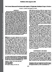
The lattice functions for the minibeta lattice with the focusing effect of the wiggler included, are shown in figure 2. It can be seen that the vertical beta is reduced to 0.5 at the wiggler, while the horizontal beta is increased. The finite dispersion in the straights is apparent. The horizontal beam emittance for this configuration is 172 nm rads, compared with 250 nm rads for the standard optic. Minibeta with 7T wiggler finite dispersion
INTRODUCTION The CAMD (Centre for Advanced Microstructures and Devices) light source in Louisiana was conceived as a 2nd generation facility of moderate brightness, principally for lithographic applications.[1] It uses a 4 cell Chasman Green lattice with a normal operating beam energy of 1.3 GeV, although up to 1.5 GeV is possible. The original mode of operation when the facility was commissioned in 1992 used a fully symmetric lattice optic as shown in figure 1.
25 20 βv 15 10 βh 5 η
0 0
Symmetric Lattice
10
20
30
40
50
60
Distance (m)
25 20
Figure 2: Lattice with minibeta and 7T wiggler, located at centre of diagram.
10η βh
15
STATUS
10
βv
5 0 0
2
4
6
8
10
12
14
Distance (m)
Figure 1: Symmetric lattice cell of CAMD. In 1998 a 7 Tesla three pole wiggler was installed.[2] By using 2 external trim dipoles, the source point at the centre pole can be adjusted to lie on axis for any peak operating field level in the wiggler. The vertical focusing effect of the wiggler can be compensated by tuning the quadrupoles in the wiggler straight, which are powered independently. It was decided in 2002 to re-adjust the quadrupoles to produce a significantly reduced vertical beta function at the wiggler, known as the minibeta configuration.[3] In addition, the finite dispersion in the long straights increases the source brightness by about a factor of two. This, together with an increased vertical source divergence, is advantageous for the energy resolution at the Selenium K-edge in the protein crystallography beam line from the wiggler.
CAMD is operated on a continuous 24 hours a day schedule. Every 2 weeks, 2 days are allocated to beam studies and maintenance, the remaining time being for users. Beam refills are scheduled 3 times a day at predetermined times. Injection is made at approximately 200 MeV from a 2 section linac. Because of the long damping time at this energy, the injection repetition rate is only 1 Hz. Good accumulation rates are routine, with up to 5 mA per shot being achievable. For best accumulation the tune point must be set to lie precisely on a coupling resonance, in order to utilize all available aperture. The beam cross section is therefore round and considerably larger than equilibrium at the injection energy. Accumulation takes place until a limitation due to the beam size is reached at between 250 and 300 mA. This beam is then ramped to 1.3 GeV and the wiggler energized, often without beam loss. The beam lifetime is limited by the vacuum pressure and presently achieves 18 hours at 100 mA. A typical 24 hour beam history is shown in figure 3. Routine refills take place at 0700, 1500 and 2200 hours.
2424
Proceedings of EPAC 2004, Lucerne, Switzerland
Table 1: Linac parameters 200 MeV ± 0.25% 2998.2MHz 1 Hz 150 ns 50 mA ±15%
Energy Energy Spread RF frequency Repetition rate Pulse Length Current Current stability Figure 3: 24 hour beam history 24 May 2004.
WIGGLER
RF SYSTEM
The maximum operating field of the wiggler[2] is 7 Tesla and it generates a total fan of 200 mrad from the central pole. The beamline from the wiggler has been increased from 2 to 4 ports and presently there are 3 beamlines installed; Micromachining, Tomography and Protein Crystallography. On request, to meet specific user requirements, the wiggler can be operated at either 5 or 7 Tesla without beamline realignment. Alignment of the magnet within its cryostat has been fine tuned to minimize consumption of liquid Helium. The traditional cryostat design with a liquid nitrogen cold screen and current leads cooled by Helium exhaust gas is fairly lossy and at 7 Tesla the optimized consumption is 70 litres per day. Refills from a 500 litre dewar are made 3 times per week.
The ex-DORIS RF cavity originally installed at CAMD was in operation for approximately 12 years and during 2002 and the beginning of 2003, slowly developed problems. With RF power applied, tiny points of light could be seen on the cavity walls observed through a viewing window. Concurrently the injected ring current became limited to 150mA, and after ramping never more than 100mA. After a long investigation of possible causes for the low current, it was decided to replace the cavity with a spare in April 2003. Conditioning of the spare cavity was facilitated by the second, currently unused, klystron, and a simple and temporary control and protection circuit for it was developed and implemented. Conditioning took place outside the ring, so no ring downtime was needed. The conditioning period took approximately one week, after which, the spare cavity was installed during a 10 day shutdown. Soon after the ring conditioning period was over, and some adjustments to the ring parameters, CAMD reached a record 392mA injected beam in June. The replaced cavity has since been chemically resurfaced and made ready to be installed as a second cavity in the CAMD ring. The result of replacing the cavity on beam current can be seen in figure 5.
INJECTOR Gun Pre-buncher Vacuum valve Beam Current Monitor Stripline
Solenoidal Focusing & Steering Triplet Steering Buncher
Accelerating Section
Figure 4: Injector at CAMD. The injector at CAMD as shown in Figure 4 consists of a 50kV triode electron gun, a 500MHz chopper prebuncher, a 4MeV, 3GHz standing wave buncher, and two 6-meter long traveling wave accelerating sections. The RF system which drives the linac consists of two 35MW, 3GHz Klystrons and modulators, RF drivers, master oscillator, etc. It can be operated in either a 2.5 ns pulse of electrons or a 50-500 ns pulse, though normally the latter is used. Operation of all these systems at 200MeV has been demonstrated (increased from 180MeV [4]). This will allow advantage to be taken of the shorter damping times which result at injection to increase the beam current in the storage ring. The typical parameters are shown in table 1:
Figure 5: Beam current before and after replacing the cavity.
MAGNET POWER SUPPLIES To improve the data logging of the magnet currents in the storage ring, current metering resistive shunts have been installed on the outputs of each of the 15 main
2425
Proceedings of EPAC 2004, Lucerne, Switzerland magnet and the 28 trim magnet power supplies. The shunts are made of manganin, having a negligible thermoelectric effect and temperature co-efficient of 15ppm. All shunts are double sized for increased thermal stability and specified for an accuracy of 0.1%. They are grouped and installed in three different metal enclosures. Each power supply has two shunts, one sized for the load at 1.3GeV (full energy) and a smaller one sized for injection. The smaller shunt can be selected by moving the power cable on terminal blocks from the larger shunt to the smaller one for calibration purposes at low energy set-points. During normal operation, the full energy shunts remain in circuit. Specially shielded cables carry the 0–100mV dc signals from the shunts to the monitoring electronics. Because the magnet power supplies are isolated from ground for safety reasons, a potential difference exists between the shunt sensing wires and ground. The larger power supplies exhibit hundreds of volts. The signals are sent to a 32 channel digital-to-analog converter (DAC) card, installed in a VME crate, but the common mode voltages must be less than about 30V above the card’s common ground. Therefore, before entering the DAC, all 15 main magnet shunt signals pass through isolation transducers (Dataforth model DSCA30-09-2) which filter and convert the 0-100mV signals to 0-10Vdc signals having 1.5kV isolation. The isolation amplifier modules have ±0.03% accuracy and ±0.01% nonlinearity. The trim magnet power supplies have a maximum voltage of less than the DAC card limit. Therefore, the negative output terminals of all the trim magnet power supplies were connected together and grounded to the accelerator signal ground bus. The DAC’s common analog ground was also connected to the same ground bus thereby resulting in a maximum voltage above ground of only 100mV for all trim shunt signals. The DAC reads these signals as 100mV as opposed to the 10V signals conditioned for the main magnet power supplies. The control system logs and archives all shunt data every 2 minutes. Historical plots of magnet currents over months can be generated to show drifting or other anomalies in magnet currents. This tool greatly increases the diagnostic capabilities of the magnet power supply system.
CONTROL SYSTEM UPGRADE A major upgrade to the CAMD control system is in process. The existing control system was developed in house, and utilizes slow CAMAC, PLC, GPIB, and RS232 controls.[5] To enhance machine operations and diagnostics, the control system needs higher speed acquisition, significantly increased data logging, easier access to archived data, post-mortem analysis, and enhanced alarm capability. As the aging I/O components and control system architecture were not up to the new demands being placed, alternatives were sought. An EPICS/VME/RTEMS solution was selected based on many factors. First, VME high speed acquisition no longer requires VxWorks, making an RTEMS based VME solution a much less expensive option. Secondly,
increased archiving, data retrieval, and alarm generating/handling requirements can easily be handled by the standard EPICS tools, eliminating the need for additional in-house development. Lastly, it was decided to utilize SLAC’s Accelerator Toolbox, providing EPICS based physics applications. The upgrade is proceeding well. EPICS/RTEMS is running on PowerPC based VME crates. BPM and power supply diagnostics acquisition rates have been increased 1000 fold. Migration tools have been developed: an interface library allowing the old control system to transparently make Channel Access calls, and a Linux based IOC to run the existing control system (see figure 6). EPICS Channel Archiver, StripTool, and Array Display Tools are in regular operation, archiving and analyzing data from both control systems. Storage Ring power supply control and ramping under VME control is currently being tested. Lastly, VME based RF controls are being developed. EPICS Applications (Accelerator Toolkit, EDM)
CAMD Applications
CAMD Channel Access Interface
CAMD Control System LINUX IOC
CAMD Control System
RTEMS/VME IOCs
Figure 6: Interim arrangement of the control system, allowing the migration from CAMAC to VME.
DIAGNOSTICS The storage ring has 19 BPMs, located adjacent to every quadrupole. (Except where one has to be omitted in the injection straight due to space limitations.) The BPMs are 4 button type with each button signal processed by a Berghoz analogue electronic module. An upgrade has been implemented to the processing and display of the BPM data. A VME system is now used which provides a sampling rate of 1 kHz, whereas the old CAMAC system could only update at 1 Hz due to network limits. The new system has the possibility of data acquisition up to 100 kHz and future plans are to use this to improve diagnostics during injection. The synchrotron light monitor has been moved from port BM1A to BM8A. This allows it to be used at injection and during the energy ramp because all the optics are now within the shield wall.
REFERENCES [1] BC Craft et al., NIM B-40/41, p373,(1989) [2] VM Borovikov et al., J Synch Rad, vol 5, p440 (1998) [3] M Fedurin et al., Proc PAC2003, pp1053-1055 [4] Y. Wang et al., Proc PAC2003, pp2892-2894 [5] P Jines et al., Proc ICALEPCS(1999), p118
2426