Improving 3D Navigation in Multiscale Environments Using Cubemap-based Techniques Daniel R. Trindade
Alberto B. Raposo
Tecgraf / Department of Informatics Pontifical Catholic University of Rio de Janeiro
Tecgraf / Department of Informatics Pontifical Catholic University of Rio de Janeiro
[email protected]
[email protected]
ABSTRACT Navigation in virtual 3D environments, especially those with multiscale features, is still a problem for many users. In this regard, a good design of the navigation interfaces is critical to ensure that the users navigate with the best possible efficiency and comfort. In this paper, we present improvements made to two well-known interfaces: fly, including support to collision treatment and automatic navigation speed adjustment in relation to scale, and examine, with automatic pivot point. Such techniques are based on the cubemap structure. Usability tests have shown a significant improvement in the execution of navigation tasks.
Categories and Subject Descriptors I.3.6 [Computer Graphics]: Methodology and Techniques— interaction techniques; I.3.7 [Computer Graphics]: ThreeDimensional Graphics and Realism—virtual reality
General Terms Image Factors, Experimentation
Keywords navigation, multiscale environments, cubemap
1.
INTRODUCTION
With the arrival of new technologies and the increasing processing power of computers, larger and richer in detail 3D virtual environments are becoming more common. Accordingly, several navigation tools were created to allow users to explore these environments. However, despite the efforts of researchers, navigation in virtual environments is still problematic for many people. There is a number of reasons for this. A frequent problem is related to the type of environment to be explored. Multiscale virtual environments [10], for instance, often require methods to allow the users to navigate through the different
Permission to make digital or hard copies of all or part of this work for personal or classroom use is granted without fee provided that copies are not made or distributed for profit or commercial advantage and that copies bear this notice and the full citation on the first page. To copy otherwise, to republish, to post on servers or to redistribute to lists, requires prior specific permission and/or a fee. SAC’11 March 21-25, 2011, TaiChung, Taiwan. Copyright 2011 ACM 978-1-4503-0113-8/11/03 ...$10.00.
scales of the environment. Multiscale environments are environments that can provide information in different levels of detail, from a single screw to an oil field spanning dozens of miles. Our goal is to propose techniques that help users navigate through multiscale environments. The solutions proposed should satisfy two main requirements: a) being as automated as possible, demanding minimal intervention by the user; and b) being independent from the type of model to be viewed, so that new types of objects can be viewed in the future without the need to develop new solutions. Moreover, the solutions are intended to work on desktop setups, using mouse and keyboard, as this setup is more common to most users [11]. In this paper, we improve on two well known navigation techniques. In the case of the fly technique, we added collision support and automatic speed adjustment in relation to the scale; in the examine technique we added a way to automatically determine the pivot point. This paper is organized as follows. In Section 2 we present related work. The cubemap concept is presented in Section 3. In Section 4, the navigation techniques are described, and in Section 5 the results of usability tests are presented. Section 6 concludes this article.
2.
RELATED WORK
Multiscale environments were first introduced in the works by Perlin and Fox [10] and Bederson et al.[3], through the creation of the Pad and Pad++ interfaces, and have been the focus of study of many researchers [14, 6, 7]. Kopper et al. [8] presented a system that allows the user to navigate through the different scales of an environment. The hierarchy of the scene models is used to define the levels of scale. However, on this approach the user is forced to issue a command to change between scales. Moreover, the adjustment of navigation parameters is only made at this time. Thus, one can say that the method proposed by Kopper et al. [8] is discrete in the sense that the different scale levels are well defined regarding their form and their location in the hierarchy of the scene. By contrast, the works presented by Ware and Fleet [12] and McCrae et al.[9] make continuous adjustments to the navigation parameters, and therefore the virtual environments do not require a well defined hierarchy of levels of scale. Ware and Fleet [12] proposed adjusting the navigation speed of the fly tool by using the depth information present in the Z buffer. To this effect, they use the smallest value resulting from scanning 15 lines of the Z buffer. McCrae et al. [9] constructed a representation of
1215
the environment called cubemap, which provides information that allows the adjustment of parameters such as speed and clipping planes, as well as offering collision support. To deal with collisions, Baciu et al. [1, 2] presented image space based techniques which consist of projecting the geometry onto an image using graphics hardware and then checking for interference, usually by analyzing the Z buffer. Calomeni and Celes [4] proposed the construction of a connectivity graph in preprocessing time. Through this graph, they are able to move the camera in order to avoid collisions with the environment. This concept was also explored by Xiao and Hubbold [13], who used force fields rather than a connectivity graph. Nonetheless, a preprocessing stage is still required to compute the fields. McCrae et al. [9] proposed using a new structure, which they call cubemap, to help construct the force map with higher resolution while eliminating the preprocessing stage altogether. The techniques introduced in the present paper are also based on the cubemap. However, the approach taken to construct the cubemap and the navigation techniques based on it had to be modified in order to fulfill the requirements of our applications, as will be described in the following sections.
3.
THE CUBEMAP
The purpose of the cubemap, as proposed by McCrae et al. [9], is to provide information about the virtual environment at a given moment. Given a camera position, this structure is constructed from 6 rendering passes, each in a different direction in order to cover the whole environment. The FOV of the camera is 900 , therefore the combination of the 6 resulting frustums yields a cube. At each pass, a shader is used to calculate the distance from the fragment generated to the camera. The computed distance values are normalized in relation to the near and far values, and stored in the alpha channel of the positions related to the fragments. Rendering is made in 32-bit float images. Such procedure is performed at each frame, or each time the camera position changes. The image resolution used for rendering does not have to be high, since only an estimation needs to be obtained. The cubemap construction process we implemented differs from the one described by McCrae et al. [9] in two aspects: 1 - the orientation of the cubemap is the same as that of the camera (McCrae et al. always used canonical directions); 2 the RGB channels of the images in the cubemap store a unit vector pointing from the position of the generated fragment to the camera. The first change was necessary to simplify the obtainment of the distance from the viewer to the center of the screen, which will be important for the automatic speed adjustment techniques of fly (Section 4.1) and for the automatic definition of the pivot point in examine (Section 4.3). The second change simplifies the construction of the force map to detect collisions (Section 4.2).
4.
NAVIGATION TECHNIQUES
In this section we will present the three improved navigation techniques.
4.1
Fly with Automatic Speed Adjustment
Navigation speed is related to the scale of the environments to be explored. Larger environments require faster speeds, while the opposite is more convenient on smaller
scales. In several applications, the scale of the virtual world does not change much and is well known, allowing a fixed navigation speed to be used. This is the case of many games, for instance. Multiscale environments, however, require a way to estimate the current scale in order to adjust the navigation speed accordingly. McCrae et al. [9] use minDist, the minimum distance in the cubemap, as an estimation to determine the current scale the camera is at. Based on that, first we developed a fly tool which could be controlled by the user by pressing the arrow keys of the keyboard to move the camera while guiding the direction of the motion with the mouse movements. Navigation speed was adjusted automatically according to equation 1. Vnav = k minDist
(1)
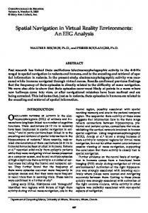
where Vnav is the adjusted navigation speed and k is a parameter of unit 1/s that causes an increase or reduction in the acceleration applied to the camera. We noticed that two situations caused discomfort and disorientation for some users. The first situation is when k is too high. In this situation, when users move away from the geometry, the camera accelerates too quickly, producing an effect similar to teleporting and making users lose their location. The second situation happens for low k values, which can considerably increase the time required to reach the intended destination, making the navigation tedious. Thus, the value of k should be selected in a way that it balances these extreme situations. In face of the difficulty of determining a value for k that suited all users, we decided to let the users define it manually, using the scroll button of the mouse. However, this led to other problems. When navigating very close to an object, some users increased the k value to move faster but forgot to readjust it when the camera was distant from the geometry, falling into the case where k is too high. The situations described reveal a disadvantage of using only minDist as an estimation to adjust the speed: when minDist is too low, it works as a break even when the user wishes to move faster. For instance, when navigating through a corridor, the user may experience slow navigation due to the closeness of the walls. Thus, it is convenient to use some other type of estimation. With that goal in mind, we attempted to use the distance to the central point of the screen. This seemed reasonable since this point represents momentarily the location the user wants to reach. Therefore, navigation speed started to be adjusted using centerDist, the distance from the camera to the center of the screen, rather than minDist. However, the use of centerDist resulted in a strange behavior. The motion of the camera ceased to be smooth and started to present peaks of speed, giving the impression that it stopped or accelerated instantly. The reason for this can be understood by observing the graph in Figure 1. This graph shows the behavior of the curves of the minDist and centerDist estimations for one path followed by the camera in a time interval of around 6 seconds. It can be seen that the minDist curve is smooth while the centerDist curve is noisier, displaying some peak values that are completely inconsistent with the general behavior of the curve. This is related to the freedom the fly tool gives to the user, who can turn the camera to any direction at any time. At a
1216
(m) 1600 1200 centerDist
800 400 0 0.0
minDist (s) 1
2 3 4 Distance x Time
5
6
Figure 1: Graph representing the behavior of the minDist and centerDist curves. given moment, the central point of the screen may fall on an object that is distant from the camera. The user then can turn the camera almost instantly toward a close-by object, leading the value of centerDist to drop abruptly. This is reflected in the speed adjustment, creating a steep deceleration. These effects do not happen when minDist is used as estimation because it is independent from the orientation of the camera. To avoid the situations caused by the peak values of the centerDist curve, we smoothened it by applying an exponential moving average (EMA): EM Ai = EM Ai−1 + A (centerDisti − EM Ai−1 )
(m) 1500 A = 0.01
1300 1200 1100 1000 2.0
2.4
2.8 3.2 Distance x Time
3.6
4.2
A = 0.04 A = 0.1 Original Curve (s) 4.0
Figure 2: Effect of applying the EMA to a curve. smoothening the centerDist curve, we can use it to adjust the speed. But one last problem remained: when the camera was close to a geometry but pointed to a location at a great distance, the navigation speed tended to increase, albeit smoothly, until it converged to centerDist again. In some situations this can be undesirable from the user’s point of view, such as when the camera is inside an object but the user wishes to view its outer parts. In this case, the user has to navigate out of the object and then point the camera toward this object. During the procedure of navigating out of the object, the camera might point to a location far away
Collision Detection and Treatment
Not allowing the camera to cut through objects in a virtual environment can be crucial in some situations [5]. McCrae et al. [9] used information from the distance cube to obtain a collision factor that causes the camera to smoothly dodge the closest objects. The idea is that each point in the cubemap located at a distance smaller than a given radius r produces a repulsion factor given by: F (x, y, i) = w(dist(x, y, i)) norm(pos(x, y, i) − camP os) (3)
(2)
In equation 2, EM Ai is the smoothed value of centerDisti at instant i, EM Ai−1 is the value smoothed at instant i − 1, and A is a constant that influences how smooth the new curve will be and how quickly this curve will converge to the centerDist values. The smaller A is, the smoother the curve will be and the higher the time needed for such convergence to take place. The maximum value of A = 1 is equivalent to the original curve. Figure 2 shows the results of smoothening an interval of the centerDist curve (represented by the darker line) for three different values of A. By
1400
from the object for a time span long enough to increase the speed too much. This is because the scale perception provided by minDist is no longer present. In such cases, minDist acts as a break, preventing the camera from moving far away too quickly. To solve this final issue, values of centerDist higher than n × minDist were discarded. This way, minDist serves as a criterion to decide when a centerDist value should or not be considered inconsistent. This solution reflects a hybrid use of the minDist and centerDist estimations: while centerDist ensures that speed adjustment is closer to what the user intends, minDist acts as a break in cases when the speed would be too high. The result is an increased comfort for the user when using this tool, as will be demonstrated by the usability tests.
w(d) = e
(r−d)2 σ2
(4)
where F (x, y, i) is the repulsion factor produced by point p referring to position (x, y) of image i of the cubemap. Value dist(x, y, i) is the distance from p to the camera. The term pos(x, y, i) is the position of p in world space, and camP os is the camera position. Function norm(v) indicates the normalized vector of v. In equation 4, σ is a parameter that indicates the smoothness of the collision factor. The higher σ is, the smoother will be the calculated factor. Considering a spherical region with radius r and centered on the camera position, equation 4 results in determining a collision penalty that grows exponentially from the moment when point p enters this region. The repulsion factors referring to equation 3 are computed for each position in the cubemap where d < r and then are combined into a single factor: X 1 F (x, y, i) (5) Fcollision = 6 cubeRes2 x,y,i where cubeRes is the resolution of the distance cube. When we applied the factor given by equation 5 to the camera, the fly tool behaved as described in the previous section: as the camera moves, Fcollision ensured that it smoothly deviate the objects that crossed its path. The behavior obtained is similar to the assisted navigation described previously [13, 4], whereby the user can navigate through the environment without worrying about choosing a collision-free path as the system is in charge of this task. It is a different approach from the one used by McCrae et al. [9], who employ Fcollision combined with the POI technique, a more restrictive solution which does not give the user total control over the camera when navigation is being performed.
4.3 1217
Examine with Automatic Pivot Point
The examine tool allows any object or location in the scene to be inspected. Basically, its functioning corresponds to rotating the camera around a point, called pivot point. In our test application, drag movements using the left mouse button made the camera rotate around the pivot point, which can be chosen by the user. Dragging vertically or horizontally with the right mouse button caused the camera to zoom in or zoom out, respectively. When the scroll mouse button is present, it can also be used for zoom operations. The location of the pivot point is crucial for the proper functioning of the examine tool. If it is not specified correctly, the camera can display behaviors which, from the user’s point of view, would seem confusing. Figure 3 illustrates two of these cases. In case (i), the pivot point (referred
1
(ii)
2
1
pivot
2
(i)
pivot
Figure 3: Problems related to the pivot point: (i) pivot point located outside the field of vision; (ii) pivot point mapped beyond the object. to as pivot in the image) is located outside the user’s field of vision, too distant from the object to be inspected. When the examine tool is used, a rotation (from camera position 1 to 2) is made around the pivot which is mathematically correct. For the user, however, this operation leads to a completely unexpected motion. This problem is worse when the pivot is located at a great distance from the model: the greater the distance, the higher the angular speed of the camera and, as a consequence, the bigger will be the error perceived by the user. Informal observations showed that this situation occurred rather often in our test application. In the case of (ii), the pivot is within the viewing angle of the camera but is located outside the object of interest. As can be seen in the image, pivot is beyond the model, and the rotation around it has the effect of a pan operation. Analyzing these situations, it can be concluded that they are basically caused by one reason: the pivot point is not located at a point corresponding to the object to be examined. Usually, 3D visualization applications that make use of the examine tool include a button (or any other interface item) that, when selected, allows a new pivot point to be chosen. We observed that some people, even more experienced users, at some point forgot to select an adequate pivot point before starting to rotate around the object of interest.This occurred especially when some users switched from the fly to the examine tool, as they attempted to rotate the camera around the object located in front of them before readjusting the pivot point. And, even when the users did not forget to perform this last operation, they reported feeling upset with the fact that they had to do it explicitly. The solution we found for this was to automatically determine a pivot point at the moment the examine tool is activated. Using the point corresponding to the center of
the screen as the new pivot, it is possible to establish a behavior that seems natural from the user’s point of view. All the user needs to do is point the camera to the object of interest and then select the examine tool. It is reasonable to expect this to happen, as in most cases the users only decide to examine an object once it is in front of them. However, the object might not necessarily be located exactly in the direction of the center of the screen; in fact, the pivot point could be mapped to an object behind the one the user wishes to examine. In this case, the user would experience the effect of a pan operation, as shown in (ii) in Figure 3. Another possibility is that the central point of the screen does not correspond to any valid point in the geometry, and thus determining pivot is impossible. To avoid these problems, the smallest distance present on the front face of the distance cube, minF ront, is used. When the central point is not valid, pivot is adjusted to the point that is minF ront away from the camera. This way, the angular speed of the rotation of the examine tool will be coherent with the scale in which the camera is located, preventing it from making excessively quick movements. The minF ront estimation is also used when the pivot point is mapped to a distant point located behind the object. In this case, minF ront can act as a restriction in the sense of identifying and correcting situations that could lead to an odd camera behavior. The idea is not to allow pivot to be adjusted to a point whose distance is greater than k × minF ront. This solution does not solve the problem definitively, but reduces its effects adequately.
5.
USER TESTS
The techniques presented in the previous section have as their main goal on assisting the users in the task of exploring virtual environments. From the user’s point of view, this should result in a more comfortable navigation experience and less prone to errors. To verify this, usability tests were carried out with two groups of users, with the purpose of gathering their opinions about the solutions developed.
5.1
Test Environment
The tests were performed using the SiVIEP viewer, a project under development by TecGraf in cooperation with Petrobras. SiVIEP supports a comprehensive visualization of several types of models comprising an oil exploration and production enterprise. For example, it is possible to load from oil platforms to wells and reservoirs in a single scene (Figure 4). The main characteristic of the virtual environments resulting from this integration is that they are multiscale.
5.2
User Profiles
Twelve people were selected to carry out the tests. They were divided in two groups: advanced users, with experience in the use of 3D visualization and 3D modeling applications who use this type of software at least once in a month; and non-advanced users, with little experience with 3D visualization applications, except for some electronic games, and who do not use 3D visualization applications frequently. From the 12 individuals, 7 were allocated in the first group and 5 in the second group. All of them had the following characteristics in common: they were between 20 and 30 years old, were males, and did not have any previous contact
1218
Figure 4: SiVIEP: visualization of an oil enterprise. In the first image, a complete oil field can be seen. Then the camera reaches the scale of a platform. Finally, the interior of the platform can be navigated. with the application used in the tests. The individuals in the advanced group of users are herein called PA1 to PA7, while the test users in the non-advanced group are identified as PN1 to PN5.
5.3
• S3: I did not have any difficulty with the pivot-point tool. • S4: I did not feel disoriented at any moment when navigating in the virtual environment.
Procedures Adopted
Each person was first asked to read and sign a consent agreement to confirm their commitment to taking the test. They were then given an overview of SiVIEP, seeing a presentation of the application and its functionalities. The test consisted basically in asking the subjects to use two different versions of SiVIEP: • Automated : this version supports the solutions discussed in the preceding sections. The user does not have to worry about speed adjustment, collisions are prevented automatically, and the explicit use of the pivot-point tool is not necessary. • Manual : this version does not include any of the improved techniques previously mentioned. The speed in the fly tool must be adjusted manually with the mouse scroll button, the user must be careful to not collide with the models, and the pivot-point tool has to be used always before beginning to inspect an object with the examine tool. Before each person started to use one of the versions, some instructions were given about the functioning of the navigation tools in that version. In the manual version, for instance, the users were asked to avoid crossing through the models in the scene and instructed on how to make manual speed adjustments and to operate the pivot-point tool. The test environment for both versions consisted of a scene containing two oil extraction platforms, A and B, a certain distance apart from each other. The camera was initially placed in a position where both platforms could be seen. The users were asked to navigate to platform A using the fly tool. Once there, they had to explore the internal areas of the platform in order to select any three objects to be inspected with the examine tool. Finally, the users were asked to navigate from platform A to platform B. After using each version, the users were asked to answer a questionary aimed at gathering their impressions about the tools used. This questionary consisted of the following statements: • S1: I did not have any difficulty with the speed adjustment of the fly tool. • S2: I was able to perform the tasks without colliding with the environment.
• S5: I felt comfortable using the navigation tools. Below each of these statements there was a scale of ten numbers, from 1 to 10, 1 meaning that the user disagrees completely with the statement and 10 meaning that the user fully agrees with it. At the end of the form there was a blank space where the users could textually describe their general impressions and justify the grades given. After both versions had been used, the users were asked to fill out a final survey consisting of two written questions: • Q1: Which of the two approaches did you prefer: the automated navigation techniques or the manual techniques? Why? • Q2: With regard to the approach you preferred, in your opinion could something be improved? If affirmative, what is it and why would it need to be improved? Lastly, the order in which the versions were presented to each user was not the same. The first person to take the test used the manual version first, and then the automated one. The second took the test in the opposite order. This pattern was followed until the last user. This measure was taken with the purpose of minimizing the learning effect of using the first version over the second.
5.4 5.4.1
Results Non-Advanced Group
Tables 1 and 2 show the results obtained after the application of the tests to the group of non-advanced users. They include the grades given by each individual to the 5 statements presented in the previous section. Table 1 provides the grades referring to the use of the manual version, while Table 2 contains the grades given to the automated version. The final column in each table shows the average grade for each statement. For a better view of the general results, these averages are presented side by side in Figure 5. The confidence interval used in the generation of this graph was 90 %. We applied a two-tailed paired t-test to compare the average of the results for both versions. We obtained t(4) = −6.43, p = 0.001, which allows us to affirm that this group preferred the automated version of the navigation. When using the manual version, users complained especially about
1219
PN1
PN2
PN3
PN4
PN5
Avg
PA1
PA2
PA3
PA4
PA5
PA6
PA7
Avg
S1
7
8
10
9
5
7.8
S1
10
9
7
7
10
9
9
8.7
S2
6
5
7
7
2
5.4
S2
3
7
7
7
10
8
7
7.0
S3
6
9
8
7
3
6.6
S3
7
8
10
3
5
5
7
6.4
S4
4
8
7
9
1
5.8
S4
3
9
6
5
10
6
8
6.7
S5
5
8
9
10
4
7.2
S5
6
8
8
8
10
8
7
7.8
Table 1: Results of the usability test for the manual version (group of non-advanced users).
Table 3: Results of the usability test for the manual version (group of advanced users).
PN1
PN2
PN3
PN4
PN5
Avg
PA1
PA2
PA3
PA4
PA5
PA6
PA7
Avg
S1
9
10
10
10
9
9.6
S1
7
5
10
5
9
9
9
7.7
S2
10
10
10
10
10
10.0
S2
10
9
9
10
10
9
10
9.6
S3
10
8
10
10
10
9.6
S3
10
6
6
10
10
9
10
8.7
S4
10
10
9
10
10
9.8
S4
6
9
7
10
10
8
9
8.4
S5
10
9
10
10
10
9.8
S5
10
6
9
9
10
9
9
8.9
Table 2: Results of the usability test for the automated version (group of non-advanced users).
Table 4: Results of the usability test for the automated version (group of advanced users).
Figure 5: Comparative results between the manual and the automated version (non-advanced users.)
Figure 6: Comparative results between the manual and the automated version (advanced users.)
the difficulty to control the camera speed in order not to collide with the environment. One of the users, for instance, reported that “the program is somewhat abrupt, which makes its use difficult for someone who is not used to or does not have enough dexterity for 3D games and software”. The lack of collision treatment caused situations in which some people felt lost. When these situations occurred, 2 of the 5 users mentioned that they would like to quit the task. The written answers confirm the statistic results. For question Q1, all users in this group replied that they preferred the automated version rather than the manual one. In the justifications, most users mentioned that the techniques provided by the automated version made navigation simpler, less prone to errors, and easier to control. As for question Q2, none of these users considered that any improvement was necessary to their preferred version.
ceived higher grades in all statements with the exception of S1, which sought to evaluate the automatic speed adjustment of the fly tool. Analyzing the justifications to the grades and the general comments made by each of these users revealed some interesting points. Almost all advanced users who gave a lower grade to the automatic speed adjustment reported that, when getting very close to an object, the camera would become too slow and it would take a while until they were able to move away from the object again. These users felt impatient about this situation, and this feeling was made worse by the fact that no control option was provided to allow them to momentarily increase the speed. Nonetheless, the same users noted that the automatic adjustment was good because it allowed them to be less concerned with the controls and helped them avoid some errors, which is in agreement with the general comments made by the non-advanced users. In summary, the advanced users wished they were offered some sort of control which allowed them to make a more “customized” adjustment at certain moments, while at the same time including automatic speed adjustment. The greatest contributions of the automated version were related to statements S2 and S3, which aimed at evaluating the efficacy of collision treatment and automatic pivot point, respectively. The users could easily notice the effects provided by these techniques and were very satisfied with their results. Some users expressly stated that, thank to these techniques, they did not make certain errors and were able to focus less on interface issues. Finally, the grades
5.4.2
Advanced Group
Tables 3 and 4 show the results obtained after the application of the tests to the group of advanced users. The results are presented in the same format as those in the previous section. Figure 6 also shows a comparison between the grades given to the manual version and those given to the automated version. The confidence interval was 90 %. We applied a two-tailed paired t-test to compare the average of the results for both versions. We obtained t(4) = −2.1, p = 0.09, which does not allow us to affirm that this group preferred the automated version of the navigation. Nevertheless, as can be observed, the automated version re-
1220
given by the users in the advanced group to statements S4 and S5 demonstrate that they felt more comfortable and experienced less moments of disorientation while using the automated version. Regarding the final survey answered by the users, 6 out of the 7 advanced users stated in Q1 that they preferred the automated version rather than the manual one. Only user PA2 preferred the latter. In the justification, this user mentioned the problem with the automatic speed adjustment and the lack of feedback to the user about the location of the pivot point when using automatic adjustment. Finally, in question Q2, which asks for suggestions about what could be improved in the preferred version, all of them asked for some kind of control that allows them to momentarily increase the speed. This leads us to assume that advanced users have a greater tendency to prefer solutions that make the tools simple to use but that are not completely automated. The opposite might be said of non-advanced users: due to their lack of experience, they prefer approaches that minimize the need to adjust the parameters of the navigation tools.
6.
CONCLUSIONS
This work presented some techniques to assist and facilitate the task of navigating 3D virtual environments. They were based on the construction and maintenance of a data structure called cubemap [9]. Improvements were proposed for the examine tool, with the addition of a way to automatically determine the pivot point, and for the fly tool, in which collision support and automatic speed adjustment in relation to the scale were implemented. To verify the efficacy of the solutions proposed, usability tests were performed. The results allow us to conclude that the techniques presented here improve the navigation experience of the users. From the 12 subjects of the usability tests, 11 preferred the version of the application that included the techniques proposed. In particular, the automatic adjustment of the pivot point in the examine tool and the collision support implemented in the fly tool had a significant positive impact in user experience. Navigation in 3D environments still presents issues and is plenty of challenges. Multiscale environments, which are becoming more common, bring further problems to be solved in terms of navigation. We believe the techniques showed in this work contribute toward providing solutions to some of the problems identified regarding navigation in these environments.
7.
ACKNOWLEDGMENTS
The authors thank Petrobras for this research support and for the software used in this research (SiVIEP). D. Trindade thanks CAPES and A. Raposo, FAPERJ (#E26/102.273/2009) for the individual support granted to this research.
8.
REFERENCES
[1] G. Baciu and W. S.-K. Wong. Rendering in object interference detection on conventional graphics workstations. In Proceedings of the 5th Pacific Conference on Computer Graphics and Applications, pages 51–58. IEEE Computer Society, 1997.
[2] G. Baciu, W. S.-K. Wong, and H. Sun. Recode: an image-based collision detection algorithm. In Proceedings of the 6th Pacific Conference on Computer Graphics and Applications, 1998. [3] B. B. Bederson, L. Stead, and J. D. Hollan. Pad++: advances in multiscale interfaces. In CHI ’94: Conference companion on Human factors in computing systems, pages 315–316. ACM, 1994. [4] A. Calomeni and W. Celes. Assisted and automatic navigation in black oil reservoir models based on probabilistic roadmaps. In I3D ’06: Proceedings of the 2006 symposium on Interactive 3D graphics and games, pages 175–182. ACM, 2006. [5] R. de Sousa Rocha and M. A. F. Rodrigues. An evaluation of a collision handling system using sphere-trees for plausible rigid body animation. In SAC ’08: Proceedings of the 2008 ACM symposium on Applied computing, pages 1241–1245. ACM, 2008. [6] G. W. Furnas and B. B. Bederson. Space-scale diagrams: understanding multiscale interfaces. In CHI ’95: Proceedings of the SIGCHI conference on Human factors in computing systems, pages 234–241. ACM Press/Addison-Wesley Publishing Co., 1995. [7] S. Jul and G. W. Furnas. Critical zones in desert fog: aids to multiscale navigation. In UIST ’98: Proceedings of the 11th annual ACM symposium on User interface software and technology, pages 97–106. ACM, 1998. [8] R. Kopper, T. Ni, D. A. Bowman, and M. Pinho. Design and evaluation of navigation techniques for multiscale virtual environments. In VR ’06: Proceedings of the IEEE conference on Virtual Reality, pages 175–182. IEEE Computer Society, 2006. [9] J. McCrae, I. Mordatch, M. Glueck, and A. Khan. Multiscale 3D navigation. In I3D ’09: Proceedings of the 2009 symposium on Interactive 3D graphics and games, pages 7–14. ACM, 2009. [10] K. Perlin and D. Fox. Pad: an alternative approach to the computer interface. In SIGGRAPH ’93: Proceedings of the 20th annual conference on Computer graphics and interactive techniques, pages 57–64. ACM, 1993. [11] B. Sousa Santos, P. Dias, A. Pimentel, J.-W. Baggerman, C. Ferreira, S. Silva, and J. Madeira. Head-mounted display versus desktop for 3d navigation in virtual reality: a user study. Multimedia Tools Appl., 41(1):161–181, 2009. [12] C. Ware and D. Fleet. Context sensitive flying interface. In SI3D ’97: Proceedings of the 1997 symposium on Interactive 3D graphics, pages 127–130. ACM, 1997. [13] D. Xiao and R. Hubbold. Navigation guided by artificial force fields. In CHI ’98: Proceedings of the SIGCHI conference on Human factors in computing systems, pages 179–186. ACM Press/Addison-Wesley Publishing Co., 1998. [14] X. L. Zhang. Multiscale traveling: crossing the boundary between space and scale. Virtual Reality, 13(2):101–115, 2009.
1221