Journal of Instruction-Level Parallelism 3 (2001)
Improving Bandwidth Utilization using Eager Writeback Hsien-Hsin S. Lee
[email protected]
Gary S. Tyson Department of Electrical Engineering and Computer Science University of Michigan, Ann Arbor, MI 48109
[email protected]
Matthew K. Farrens Department of Computer Science University of California, Davis, CA 95616
[email protected]
Abstract Cache memories have been incorporated into almost all modern, general-purpose microprocessors. To maintain data consistency between cache structures and the rest of the memory systems, most of these caches employ either a writeback or a write-through strategy to deal with store operations. Writethrough caches propagate data to more distant memory levels at the time each store occurs, producing a significant bus traffic overhead to maintain consistency between the memory hierarchy levels. Writeback caches can significantly reduce the bandwidth requirements between caches and memory by marking cache lines as dirty when stores are processed and writing those lines to the memory system only when that dirty line is evicted. Writeback caches work well for many applications; however, for applications that experience significant numbers of cache misses over a very short interval due to streaming data, writeback cache designs can degrade overall system performance by clustering bus activity when dirty lines contend with data being fetched into the cache. In this paper we present a technique called Eager Writeback, which avoids performance loss due to clustered memory traffic patterns found in streaming and graphics applications by speculatively ”cleaning” dirty cache lines prior to their eviction. Eager Writeback can be viewed as a compromise between write-through and writeback policies, in which dirty lines are written later than write-through, but prior to writeback. We will show that this approach can effectively avoid the performance degradation caused by clustering bus traffic in a writeback approach, while incurring very minimal additional memory traffic.
1
Introduction
Caches are very effective at reducing memory bus traffic by intercepting most of the read requests generated by the processor and servicing the requests with data retained in the cache. To accomplish this, caches must maintain a consistent storage state in the presence of both reads and writes to memory. Generally, support for writes (or stores) tends to be simple – on a store the data item is either written into the cache and through the cache hierarchy to the memory (referred to as a write-through policy), or it is written into the cache exclusively and the data item is written out to memory only when the cache line is evicted (known as a writeback policy). Caches employing a write-through policy generate memory traffic to the next level of the cache hierarchy or memory system for each store request. Since it largely defeats the purpose of having a cache if the processor has to block on each store until the write completes, write-through caches use a structure known as a store buffer or write buffer [13] to buffer writes to memory. Whenever a write occurs, the data item is written into both the cache and this structure (assuming the store buffer is 1
not full), allowing the processor to continue executing without blocking. The store buffer will send its contents to memory as soon as the bus is idle. Writeback caches, on the other hand, generate memory traffic much less frequently. When a store occurs in a writeback cache the data value is written into the corresponding line in the cache, which is then marked dirty. Writes to memory occur only when a line marked dirty is evicted from the cache (usually due to a cache miss for some other memory block mapped to the same cache line) in order to make room for the incoming data item. Whenever there are clustered misses (caused by context switches, or working set changes in an application) the writeback cache can find itself blocked waiting for a dirty line to be written back to memory. This is similar to the problem faced by the write-through cache, and can be dealt with in much the same manner by adding a writeback buffer. However, there are certain classes of programs which suffer from memory delay penalties that even a large writeback buffer cannot eliminate. For example, many emerging applications (e.g. 3D graphics or multimedia) have enormous incoming data streams. Due to the finite capacity of the data caches, in these programs, the stream of incoming data items can cause many conflict cache misses over a very short time frame and trigger the eviction of many dirty lines. This dirty writeback traffic must compete for available memory bandwidth with the arriving data, and often impedes the delivery of the data to the processor. For programs where overall performance is bound by memory bandwidth, this competition for bandwidth can have a substantial negative impact. In this paper we propose a modification to the writeback policy which spreads out memory activity by speculatively writing certain dirty lines to memory whenever the bus is free, instead of waiting until that line in the cache is replaced. This early writing of dirty lines to the memory system reduces the potential impact of bursty reference streams, and can effectively re-distribute and balance the memory bandwidth and thereby improve system performance. In Section 2 we describe this problem in a concurrent system architecture, in Section 3 we describe our “Eager Writeback” strategy, in Section 4 we present the simulation infrastructure and benchmarks used in this study, in Section 5 we discuss the results, and Section 6 presents our conclusions.
2
Memory Subsystem
Modern high-performance and embedded processors provide several different memory attributes so that programmers and compilers can manipulate application data in a more flexible manner. These memory attributes generally contain the following basic types — uncacheable, cacheable, transient, write-combinable and cache locking. Uncacheable and cacheable are the most commonly used memory attributes, with the cacheable memory type typically implemented using a writeback or a write-through policy. The transient memory type is primarily used for data that demonstrates spatial but not temporal locality. Thus, transient type data will have a shorter life expectancy. The write-combinable type is a specially tailored memory type for multimedia applications, used to write out graphics or image data more efficiently. It collapses byte or word writes into an internal buffer (in cache line size) and evicts them later when the buffer is filled or displaced. Finally, the cache locking memory type is essentially the opposite of the transient memory type. Data declared as this type will be locked in the cache during execution. The operating system can designate a memory attribute to a specified memory region at the page granularity through system flags and registers. As discussed in Section 1, caches that employ a writeback policy reduce memory traffic by delaying the transfer of data to memory as long as possible. Many modern microprocessors using a writeback cache policy incorporate a writeback (or cast-out) buffer, which is used as temporary storage space for holding dirty cache lines while the data request that caused the eviction is serviced. Upon eviction, the displaced dirty cache line is deposited into the writeback buffer, which usually has the highest bus scheduling priority among all types of non-read bus transactions. Once the writeback buffer fills 2
up, subsequent dirty line replacements cannot take place, and their corresponding data demand fetch operations cannot be committed into the cache before the writeback buffer is drained. This causes the processor pipeline to stall waiting for the dependent data. It is possible to alleviate this problem somewhat by using existing cache hardware. Non-blocking caches have been proposed by Kroft [8] which use a set of miss status holding registers (MSHRs) to manage several outstanding cache misses. When a cache miss occurs in a non-blocking cache, it is allocated an empty MSHR entry. Once the MSHR entry is allocated, processor execution can continue. If none of the MSHRs are available (i.e. a structural hazard [5] exists due to resource conflicts), the processor will have to block until an MSHR entry becomes free. By adding data fields to the MSHRs, it would be possible to use them to temporarily store returning cache lines. This would allow fetched data to be immediately forwarded to the appropriate destination registers, and help overcome the situation where the cache cannot be written to because the writeback buffer is full. However, this scenario delays MSHR deallocation and can lead to processor stalls on a cache miss if there are no free MSHRs. Figure 1 illustrates a non-blocking cache organization. Cache Miss Address
Set-Associative Cache way0
LRU bits
MSHRs
set0
Block Address
Data Forward Path
Data
Writeback Buffer Block Addr
Data
Data Return
Next Level Cache/Memory
Figure 1: Block Diagram of Non-blocking Caches. In addition, in a modern computer system memory bandwidth is not exclusively dedicated to the host processor. There are often multiple agents on the bus (such as graphics accelerators or multiple processors) issuing requests to memory over a short period of time. In a contemporary multimedia PC platform with an Accelerated Graphics Port (AGP) interface running a graphics-centric application, for example, the graphics accelerator shares system memory bandwidth with the host processor in order to retrieve graphics commands and texture maps from the system memory. A typical system architecture of a contemporary multimedia PC system is illustrated in Figure 2. In a common 3D graphics application, the processor reads instructions and triangle vertices, performs the specified computations, and then stores them with rendering state commands back into AGP memory space, usually configured as an uncacheable region. The graphics accelerator then reads these commands out of AGP memory for rasterization that draws filled polygons on the display. In addition to the command traffic, the graphics accelerator also reads a large amount of texture data (which constitutes the major portion of AGP traffic on the bus). These textures are mapped onto polygon surfaces to increase the visual realism of computer-generated images. With richer content 3D graphics applications/games or graphics accelerators with enhanced quality features such as bi-linear/tri-linear interpolation, AGP command and data bandwidth demands for graphics accelerators will undoubtedly 3
be even greater than they are now. Current cache designs have difficulty in efficiently managing the flow of data in and out of the cache hierarchy in these data intensive applications. Buffering techniques such as write buffers and MSHRs can help, but do not alleviate the problems of clustering bus traffic caused by writeback data. In the next section we introduce a new technique designed to distribute the writes of dirty blocks to times when the bus is idle. The Host Processor L2 Cache
Core Processor
Graphics Processor
A.G.P.
Frontside Bus
Backside Bus
System Memory (DRAM)
Chipset
Command and Texture Traffics
Textures
Local Frame Buffer
I/O
I/O
I/O
Figure 2: A Multimedia PC Architecture.
3 3.1
Eager Writeback Overview
To address the performance drawbacks of a conventional writeback policy, we have developed a novel technique called Eager Writeback. The fundamental idea behind Eager Writeback is to write selected dirty cache lines to the next level of the memory hierarchy and clear their dirty bits earlier than would happen in a conventional writeback cache design, in order to better distribute bandwidth utilization and alleviate memory bus congestion. If dirty cache lines are written to memory when the bus is less congested, there will be fewer dirty lines that require eviction during peak memory activity. In essence, we are speculating that once dirty lines enter a certain state, they will not be written to again before eviction. Thus, there is no need to wait until eviction time to perform the cache line write. Note that an Eager Writeback will never impact the correctness of the architectural state even if the operation that triggers it was wrongly speculated - if the speculation was incorrect and writes occur too often, we approach the limiting case of write-through cache behavior. If we do not speculate often enough, we approach the behavior of a writeback cache. However, in either case no correctness constraints will be violated. This work is similar in spirit to that of Lai and Falsafi [9], in which they identify cache lines in a shared memory system that can be speculatively self-invalidated in order to hide the invalidation time and reduce the coherence overhead. However, we are applying the idea to uniprocessor caches instead of DSM machines, which enables us to use a far simpler mechanism to identify which lines should be speculatively written out. In order to identify which lines are the best candidates for being speculatively cleaned, we examined the probability of rewriting a dirty line in a set-associative cache when it was in a given state (MRU 4
Probability of rewriting to a dirty line in each LRu stack of L1 cache (Spec95 Benchmark) 129.compress 099.go 126.gcc 130.li 132.ijpeg 134.perl 101.tomcatv 103.su2cor 107.mgrid 145.fpppp 146.wave5 Average
0.9 0.8
Probability of Rewrite
0.7 0.6 0.5 0.4
0.8 0.7 0.6 0.5 0.4 0.3
0.2
0.2
0.1
0.1
MRU
MRU-1 LRU+1 4-way assoc cache: MRU -> LRU
129.compress 099.go 126.gcc 130.li 132.ijpeg 134.perl 101.tomcatv 103.su2cor 107.mgrid 145.fpppp 146.wave5 Average
0.9
0.3
0
Probability of rewriting to a dirty line in each LRu stack of L2 cache (Spec95 Benchmark)
1
Probability of Rewrite
1
0
LRU
MRU
MRU-1 LRU+1 4-way assoc cache: MRU -> LRU
LRU
Figure 3: Probability of writing to a dirty line in each LRU stack of L1 and L2 caches (SPEC95)
1
Probability of rewriting to a dirty line in each LRU stack of L1 cache (X Benchmark)
0.8
0.8
0.7
0.7
0.6 0.5 0.4
0.6 0.5 0.4
0.3
0.3
0.2
0.2
0.1
0.1
0
MRU
MRU-1 LRU+1 4-way assoc cache: MRU -> LRU
LRU
XDOOM demo POV-ray Animation viewer Xlock-mountain Average
0.9
Probability of Rewrite
Probability of Rewrite
0.9
Probability of rewriting to a dirty line in each LRU stack of L2 cache (X Benchmark)
1
XDOOM demo POV-ray Animation viewer Xlock-mountain Average
0
MRU
MRU-1 LRU+1 4-way assoc cache: MRU -> LRU
LRU
Figure 4: Probability of writing to a dirty line in each LRU stack of L1 and L2 caches (X benchmark)
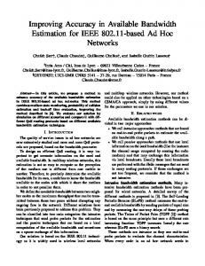
through LRU) for the well-known SPEC95 benchmarks [4] and four applications from the lesser-known X benchmark suite [12]. The X benchmark suite consists of four applications representing different graphics algorithms based on X Windows. X-DOOM, a popular video game, uses a polygon-based rendering algorithm. POV-ray is a public domain ray tracing package developed for generating photorealistic images on a computer. xlock, a popular screen saver, renders a 3D polygonal object on the screen. The final application is an animation viewer which processes an MPEG-1 data stream to display an animated sequence. Our results indicate that cache lines that have been marked dirty and reach the LRU (Least Recently Used) state in a 4-way set-associative data cache are rarely written to again before they are evicted. In Figure 3 and Figure 4, we show the probability of a line that was marked dirty being written to again as it moves from the MRU (Most Recently Used) state to the LRU state for both L1 and L2 caches. The cache configurations are described in Table 1. The graph on the left in Figure 3, for example, shows that in the L1 cache the average probability (the solid line) of a dirty line in the LRU state being re-written is 0.15, while the similar probability for a dirty line in the MRU state is 0.95. The probabilities of re-dirtying lines in the LRU state are even lower in the L2 cache - in fact, close to 0 as shown in the graphs on the right of Figure 3 and Figure 4. These figures indicate there are some programs (such as 103.su2cor and 145.fpppp) that do have a fairly high probability of writing to dirty lines after they have entered the LRU state, however. In order to further evaluate these cases, we looked at the ratio of the number of times a dirty line in the 5
LRU state is written to, normalized to the number of times a dirty line in the MRU state is written to. The results are presented in Figure 5, which shows that while the probabilities may be high, the actual number of these occurrences is negligible compared to the rewriting that occurs when a line is in other states (MRU, MRU-1, etc.). Two bars are shown for each state of each benchmark in this figure. Symbol # enter dirty accounts for the total number of writes including the first time writes while # re-dirty shows only the number of writes to ”dirty” lines. These trends held across a wide range of cache configurations, and imply that once a line enters the LRU state it becomes a prime candidate for Eager Writeback, since it has a very low occurrence of being written to (and marked dirty) again. L1 data writes w.r.t. MRU->LRU stack (normalized to MRU # enter dirty state), 16KB L1/512KB L2
1
MRU - # enter dirty MRU - # re-dirty MRU+1 - # enter dirty MRU+1 - # re-dirty
0.8
MRU+2 - # enter dirty MRU+2 - # re-dirty LRU - # enter dirty 0.6
LRU - # re-dirty
0.4
0.2
0
xdoom
pov-ray
gcc
fpppp
Figure 5: Normalized number of writes and rewrites to a dirty line in each MRU-LRU state
3.2
Design Issues in Eager Writeback Caches
There can be many different approaches to deciding when to trigger an Eager Writeback. As was shown in the previous section, one obvious candidate is to use the transition of a dirty line into the LRU state as a trigger point for an Eager Writeback. For example, when a cache set is being accessed and its corresponding LRU bit is being updated, the line can be checked to see if it is marked dirty. If it is, then a dirty writeback can be scheduled, and the dirty bit can be reset. Unless a later write updates this particular cache line again during its lifetime in the cache, otherwise, no additional dirty writeback will be generated for this line. If the writeback buffer is full at this point, two approaches can be considered; (a) simply abort the Eager Writeback - the actual dirty writeback will take place later when the line is evicted, or (b) perform the eager writeback when an entry in the writeback buffer becomes free. This provides the ability to perform eager writeback anytime between when a line is marked LRU and when it is evicted. To provide this capability using a minimum of hardware, we chose to implement an Eager Queue which holds attempted eager writebacks which were unable to acquire writeback buffer entries. Whenever an entry in the writeback buffer becomes available, the Eager Queue checks the cache set on the top of the queue to see if the dirty bit of the LRU line in the indexed set is set. If it is, the line is moved into the writeback buffer. Figure 6 illustrates a writeback cache organization with an Eager Queue. An alternate implementation considered during this research was Autonomous Eager Writeback. This implementation used a small independent state machine which autonomously polled each cache set in round-robin fashion and checked the dirty bit of its LRU line, initiating eager writeback on those lines when the writeback buffer was not full. Whether Eager Queues or the autonomous state machine is more feasible is highly dependent on the processor and cache organization. For this study we present results for the more conservative approach which used Eager Queues.
6
Cache Miss Address
Set-Associative Cache LRU bits
way0
MSHRs
set0
Block Address
Data Forward Path
Data
Set ID
Eager Queue
Writeback Buffer
set IDs
Block Addr
Data
Data Return
Trigger when entry freed
Next Level Cache/Memory
Figure 6: Eager Writeback Cache with an Eager Queue.
4
Simulation Framework Processor Architectural Parameters Core frequency 1st Level I-Cache 1st Level D-Cache 2nd Level Cache Cache line size I- and D-TLBs Backside bus Frontside bus Memory model Branch predictor Instr. fetch/decode/issue/commit width 1st Level Cache MSHR entries 2nd Level Cache MSHR entries Load/Store Queue size Register update unit size Memory port size INT/FP ALU size INT/FP MULT/DIV size
Specifications 1 GHz 2-way 16KB, virtual-index physical-tag 4-way 16KB, virtual-index physical-tag Unified, 4-way 512KB, physical-index physical-tag 32 bytes 2-way 8KB, 128 entries each 500 MHz (half-speed), 8B wide 200 MHz, 8B wide Rambus DRAM (peak: 1.6 GB/s) 2-level adaptive, 10-bit gshare 8/8/8/8 8 8 32 64 2 4/4 1/1
Table 1: Summary of the Baseline Processor Model. Our simulation environment was based on the SimpleScalar tool set [1], a re-targetable executiondriven simulator which models speculative and out-of-order execution. The machine employs a Register Update Unit (RUU), which combines the functions of the reservation stations and the re-order buffer necessary for supporting out-of-order execution [14]. Functional unit binding, instruction dispatch and retirement all occur in the RUU. Separate address and data buses were implemented and their contentions were all modelled appropriately. Writeback buffers were implemented between cache hierarchies. All the binaries used were compiled using the SimpleScalar GCC compiler that generates code in the Portable ISA (PISA) format, whose encoding and addressing modes are almost identical to the MIPS ISA [7]. The microarchitectural parameters used in our baseline processor model are shown in Table 1. Table 2 lists the latencies of each functional unit modelled in the simulation. A non-blocking cache structure, writeback buffer and eager queue associated with each cache level were added to the simulator 7
for this study. The number of entries in each buffer was re-configurable from 1 to 256, and varied from simulation to simulation. Note that the actual RDRAM memory access latency simulated is also determined by other side-effects, e.g. bank conflict, in addition to memory page access timings shown in the table. For example, the minimal memory access latency is 70 core clocks if the RDRAM access causes a memory page miss without any contention. Processor Parameters 1st Level I- and D-Cache 2nd Level Cache I- and D-TLBs Backside bus arbitration Frontside bus arbitration RDRAM Trcd, RAS-to-CAS RDRAM Tcac, CAS-to-data return RDRAM Trp, Row Precharge RDRAM page hit timing RDRAM row miss timing RDRAM page miss timing INT ALU latency/thruput INT multiplier latency/thruput INT divider latency/thruput FP ALU latency/thruput FP multiplier latency/thruput FP divider latency/thruput
Cycles in Processor Clocks 3 clks, thruput = 1 clk 18 clks, thruput = 10 clks 2 clks, thruput = 1 clk 4 clks 10 clks 20 clks 20 clks 20 clks 30 clks 50 clks 70 clks 1/1 3/1 20 / 19 2/1 4/1 12 / 12
Table 2: Latency Table (in core clocks) of Functional Units in the Baseline Processor. A pseudo-Rambus DRAM model was used in the external memory system. This single-channel RDRAM with a 64 split bank architecture can address up to 2GB of system memory. In the model, 32 independent open banks can be accessed simultaneously1 . Row control packets, column control packets and data packets can be pipelined and use separate busses. RDRAM address re-mapping [10] was modelled to reduce the rate of bank interference. The theoretical peak bandwidth that can be reached in our RDRAM model is 1.6GB/sec. A simplified uncacheable write-combining (or write-coalescing) memory [2][3] was implemented as well for the purpose of correctly simulating our benchmark behavior. Whenever a data write to an uncacheable yet marked as write-combinable memory region results in an L1 cache miss, the write operation will immediately request access to the bus and drive data out to the system memory directly (skipping a next-level cache look-up). Only complete cache line writes are modelled - any partial cache line update will be treated as a full cache line write in the simulator. For modelling multiple agents on the memory bus, a memory traffic injector was also implemented. This injector allowed us to imitate the extra bandwidth consumed by other bus agents by configurable periodic injections of data streams onto the memory bus.
4.1
Benchmarks
In order to evaluate the effectiveness of the Eager Writeback technique, we ran extensive simulations on the SPEC95 benchmark suite and two programs representative of future graphics and streaming applications. Concentrating the analysis on these small, representative kernels enables us to illustrate the potential benefits of our scheme in far greater detail than can be achieved running an entire application. 1 Note that a bank conflict occurs while simultaneously accessing adjacent banks that share the same sense amplifier for driving data out of the RAM cells
8
3D-geometry() while ( frames ) for ( objects in each frame ) for ( every 4 vertices ) /* Transformation */ tx = m11 ∗ InV []x + m21 ∗ InV []y + m31 ∗ InV []z + m41; ty = m12 ∗ InV []x + m22 ∗ InV []y + m32 ∗ InV []z + m42; tz = m13 ∗ InV []x + m23 ∗ InV []y + m33 ∗ InV []z + m43; w = m14 ∗ InV []x + m24 ∗ InV []y + m34 ∗ InV []z + m44; OutV []rw = 1/w; OutV []tx = Xof f set + tx ∗ OutV []rw ; OutV []ty = Yof f set + ty ∗ OutV []rw ; OutV []tz = tz ∗ OutV []rw ; /* Texture coordinates copying */ OutV []tu = InV []u ; OutV []tv = InV []v ; /* Lighting Loop */ IDr = IDg = IDb = 0.0; for ( every light source ) dot = LDir[]x ∗ InV []nx + LDir[]y ∗ InV []ny + LDir[]z ∗ InV []nz ; IDr = IDr + Ambientr + Dif f user ∗ dot; IDg = IDg + Ambientg + Dif f useg ∗ dot; IDb = IDb + Ambientb + Dif f useb ∗ dot; OutV []cd = ((int)IDr