INTERNATIONAL JOURNAL OF OPTIMIZATION IN CIVIL ENGINEERING Int. J. Optim. Civil Eng., 2013; 3(4):563-574
IMPROVING COMPUTATIONAL EFFICIENCY OF PARTICLE SWARM OPTIMIZATION FOR OPTIMAL STRUCTURAL DESIGN S. Kazemzadeh Azad*, †,1 and O. Hasançebi 1 Middle East Technical University, Department of Civil Engineering, Ankara, Turkey
ABSTRACT This paper attempts to improve the computational efficiency of the well known particle swarm optimization (PSO) algorithm for tackling discrete sizing optimization problems of steel frame structures. It is generally known that, in structural design optimization applications, PSO entails enormously time-consuming structural analyses to locate an optimum solution. Hence, in the present study it is attempted to lessen the computational effort of the algorithm, using the so called upper bound strategy (UBS), which is a recently proposed strategy for reducing the total number of structural analyses involved in the course of design optimization. In the UBS, the key issue is to identify those candidate solutions which have no chance to improve the search during the optimum design process. After identifying those non-improving solutions, they are directly excluded from the structural analysis stage, diminishing the total computational cost. The performance of the UBS integrated PSO algorithm (UPSO) is evaluated in discrete sizing optimization of a real scale steel frame to AISC-LRFD specifications. The numerical results demonstrate that the UPSO outperforms the original PSO algorithm in terms of the computational efficiency. Received: 10 August 2013; Accepted: 5 October 2013
KEY WORDS: structural design optimization, metaheuristic algorithms, particle swarm optimization, upper bound strategy, steel frame
1. INTRODUCTION The optimum design of structural systems is an attempt to find a minimum weight or cost *
Corresponding author: S. Kazemzadeh Azad, Middle East Technical University, Department of Civil Engineering, Ankara, Turkey † E-mail address:
[email protected] (S. Kazemzadeh Azad)
564
S. Kazemzadeh Azad and O. Hasançebi
structure with respect to a predefined set of design constraints. Basically, the optimum design of skeletal structures (either frame or truss structures) can be divided into three categories as sizing optimization, shape optimization, and topology optimization. In sizing optimization, cross-sectional areas of members, in shape optimization, nodal coordinates, and in topology optimization, presence or absence of structural members are treated as design variables of the problem. The shortcomings of traditional structural optimization techniques namely mathematical programming [1] and optimality criteria [2, 3] methods, such as their gradient based formulations as well as inefficiency in handling discrete design variables, have yield an increasing tendency towards non-traditional stochastic search techniques or the so-called metaheuristics. In general, metaheuristic techniques, such as genetic algorithms (GAs) [4, 5], particle swarm optimization (PSO) [6], ant colony optimization (ACO) [7, 8], etc., borrow their working principles from natural phenomena [9]; and follow non-deterministic search strategies in locating the optimum solutions. The numerous applications of metaheuristics in structural design optimization can be attributed to their superior results, robust performances, independency on gradient information, and capability of handling both discrete and continuous design variables. The state-of-the-art reviews of metaheuristic algorithms as well as their applications in structural design optimization problems are outlined in Refs. [10, 11]. Despite many advantageous features of the metaheuristics, the slow rate of convergence towards the optimum and the need for a high number of structural analyses are known as the main shortcomings of these techniques in structural design optimization applications. It is known that response computations of designs sampled during a search process mostly occupies 85-95% workload of a metaheuristic algorithm [12], and thus large number of structural analyses significantly increases the total computing time. One solution to this is to lessen the total computational time by taking advantage of high performance computing techniques, such as parallel or distributed computing methods. The idea behind these approaches is to distribute the total workload of the algorithm amongst multiprocessors of a single computer or within a cluster of computers connected to each other via local area network. In Hasançebi et al. [12] it is demonstrated through three design instances of steel buildings that a maximum speedup ratio between 12.2 and 16.8 can be achieved using a cluster computing system consisting of 32 processors. An alternative approach, which is more straightforward and easier to apply, is to develop efficient strategies for reducing the number of structural analyses required in the course of optimization. The latter, can be carried out by proposing improved optimization techniques capable of locating reasonable solutions using fewer structural analyses, i.e. less computational cost. In this regard, an upper bound strategy (UBS) is recently proposed in Kazemzadeh Azad et al. [13], where unnecessary structural analyses are avoided during the course of optimization based on a simple and efficient mechanism. The main concern in the UBS is to detect those candidate designs which have no chance to improve the search during the iterations of the design optimization. After identifying the non-improving candidate designs, they are directly excluded from the structural analysis stage, resulting in diminishing the total computational effort. The PSO algorithm proposed by Kennedy and Eberhart [6] simulates the social behavior
IMPROVING COMPUTATIONAL EFFICIENCY OF PARTICLE SWARM...
565
of animals such as fish schooling and bird flocking. Due to its efficiency and simplicity, it has become one of the most popular metaheuristics of the recent years especially in the field of structural desing optimization [14-19]. Fourie and Groenwold [14] applied the PSO algorithm to the structural design optimization problems with sizing and shape variables. Perez and Behdinan [15] investigated the PSO algorithm through optimal design of four classical truss optimization instances. Li et al. [16, 17] proposed improved variants of the method as heuristic PSO algorithms for optimum design of truss structures. Further, Kaveh and Talatahari [18] developed a hybrid version of the PSO algorithm for discrete sizing optimization of truss structures and demonstrated its promising performance. Recently, Gomes [19] employed the PSO algorithm for sizing and shape optimization of truss structures with frequency constraints. Regarding the wide application of the PSO algorithm in tackling real world instances, improving its computational efficiency in structural design optimization problems is attempted in the present study. Here, the number of structural analyses needed for the design optimization process of the PSO algorithm is diminished using the recently proposed UBS [13]. In the UBS, unnecessary structural analyses are avoided during the course of optimization using a simple and efficient mechanism. The key issue is to identify those candidate solutions which have no chance to improve the search during the optimum design process. After identifying those non-improving solutions, they are directly excluded from the structural analysis stage, diminishing the total computational cost. The performances of the UBS integrated PSO algorithm (UPSO) is investigated in design optimization of a steel frame structures according to AISC-LRFD [20] specifications; and the numerical results are discussed in detail. The remaining sections of the paper are organized as follows. The second section describes the considered discrete sizing optimization problem. The third section outlines the PSO algorithm and related formulations. In the fourth section the UBS integrated PSO algorithm is described in details. The computational efficiency of the UPSO algorithm is investigated in the fifth section. A brief conclusion of the study is provided in the last section.
2. DISCRETE SIZING OPTIMIZATION PROBLEM In industrial applications the frame members are typically adopted from a set of available steel sections which yields a discrete sizing optimization problem. For a steel frame composed of N m members grouped into N d design groups, the optimum design problem can be stated as follows. The objective is to find a vector of integer values I (Eq. 1) representing the sequence numbers of steel sections assigned to N d member groups
I T I 1 , I 2 ,..., I N d to minimize the weight, W , of the structure
(1)
566
S. Kazemzadeh Azad and O. Hasançebi Nd
W i Ai i 1
Nt
Lj
(2)
j 1
where Ai and i are the length and unit weight of the steel section selected for member group i, respectively, N t is the total number of members in group i, and L j is the length of the member j which belongs to group i. Here, the objective of finding the minimum weight structure is subjected to design constraints, including strength and serviceability requirements, imposed according to AISC-LRFD [20] code.
3. THE PSO ALGORITHM The PSO algorithm is developed considering the memory of each particle (candidate solution) as well as the knowledge attained by the swarm of particles [6, 21]. The main steps of the PSO algorithm are outlined in the following subsections [14, 15, and 22]. 3.1. Initializing Particles A swarm is composed of a certain number of particles. Each particle (P) represents a candidate solution to an optimization problem at hand, and incorporates two sets of components; a position (design) vector I (Eq. (1)) and a velocity vector v (Eq. (3)). The position vector I retains the values (positions) of design variables, while the velocity vector v is employed to vary these positions during the search. Each particle in the swarm is generated through a random initialization.
P ( I , v),
v v1 , v2 ,..., v N m
(3)
3.2. Evaluating Particles All the particles are analyzed, and their objective function values are calculated are computed according to Eq. (4) [22].
f W 1
p ci i
(4)
In Eq. (4), f is the constrained objective function value, c i is i-th problem constraint violation and p is the penalty coefficient used to tune the intensity of penalization as a whole. This parameter is generally set to an appropriate static value of unity [22]. 3.3. Updating the Particles’ Bests and the Global Best In the PSO, a particle’s best position (the best design with the minimum objective function
IMPROVING COMPUTATIONAL EFFICIENCY OF PARTICLE SWARM...
567
value) so far is referred to as particle’s best and is stored in a vector B for each particle. On the other hand, the best position located by any particle since the beginning of the process is called the global best position, and it is stored in vector G. At a current iteration k, both the particles’ bests and the global best are updated (Eq. (5)).
B ( k ) B1( k ) ,..., B i( k ) ,..., B (Nk ) m
G ( k ) G1( k ) ,..., G i( k ) ,..., G (Nk ) m
(5)
3.4. Updating Particles’ Velocity Vectors The velocity vector of each particle is updated based on the particle’s current and best positions as well as the global best position, as follows:
vi( k 1) round wvi( k ) c1r1 ( Bi( k ) I i( k ) ) c2 r2 (Gi( k ) I i( k ) )
(6)
In Eq. (6), r1 and r2 are random numbers generated between 0 and 1, w is the inertia of the particle which controls the exploration properties of the algorithm, c1 and c2 are the trust parameters that indicate how much confidence the particle has in itself and in the swarm, respectively. A reformulation of Eq. (6) is put forward in [22] where an additional velocity term is added to give each particle a random move in certain directions in the close neighborhood of its current position. The reformulation used in Ref. [22] is implemented here with a slight modification where the additional velocity term is adopted with a probability of 0.01 for both positive and negative changes in the velocities of particles. 3.5. Updating Particles’ Position Vectors Next, the position vector of each particle is updated with the updated velocity vector (Eq. (7)).
I i( k 1) I i( k ) vi( k 1)
(7)
3.6. Termination The abovementioned steps 3.2 through 3.5 are repeated iteratively for a predefined number of iterations.
4. INTEGRATION OF THE UBS WITH PSO The large number of structural analyses involved in the design optimization process of the PSO is convinced as a main shortcoming while tackling structural design optimization problems. In this regard, in this study, the recently proposed UBS [13] is integrated with the PSO algorithm to diminish the total computational cost of the technique. In the UBS, unnecessary structural analyses are avoided during the course of optimization using a simple, yet, efficient mechanism. The main concern is to identify those candidate solutions
568
S. Kazemzadeh Azad and O. Hasançebi
which have no chance to improve the search during the course of optimum design. After identifying those non-improving solutions, they are directly excluded from the structural analysis stage, diminishing the total computational effort. Typically, considering the UBS, the penalized weight of a current solution (particle) can be considered as the upper bound limit for the net weight of a newly generated candidate solution. Accordingly, a new candidate solution with a net weight greater than this limit can be excluded from the structural analysis stage. This strategy is used in the UPSO algorithm as follows. Here, after a new particle Pi is generated, first the net weight of newly generated particle i.e. W(Pi ) is calculated only; not the penalized weight. This computation is straightforward and can be accomplished through a trivial computational effort. If Pi has a net weight smaller than or equal to the penalized weight of the current particle’s best f(Gi), the structural analysis of the sampled particle is processed and its penalized weight is computed. In the opposite case, i.e. f(Gi)< W(Pi ), however, the upper bound rule is activated and Pi is automatically excluded from the structural analysis stage, since such a candidate solution is unlikely to improve the current particle’s best vector. It is worth mentioning that the UBS is originally proposed in Ref. [13] as a strategy to be used in conjunction with all metaheuristic techniques that employ a µ+λ selection scheme [23] in their algorithmic models. However, in the present study it is shown that the UBS can be efficiently used in conjunction with other search schemes such as the one involved in the PSO algorithm as well. It should be noticed that the UBS does not affect exploration and exploitation characteristics of the PSO algorithm; however, as demonstrated in the following section, using this strategy, it is possible to perform a computationally more efficient design optimization.
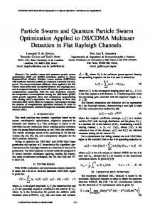
5. NUMERICAL EXAMPLE This section covers performance evaluation of the UBS integrated PSO algorithm i.e. UPSO through design optimization of a 135-member steel frame under 10 load combinations. Here, the maximum number of iterations is taken as the termination criterion of optimization process. The parameters’ values of Eq. (6) are taken as: w = 0.5, c1 = c2 = 1.5 as given in Ref. [22]. Here, the wide-flange (W) profile list composed of 268 ready sections is used to size the structural members. The material properties of steel are taken as follows: modulus of elasticity (E) 200 GPa, yield stress (Fy) 248.2 Mpa, and unit weight of the steel (ρ) 7.85 ton/m3. It should be underlined that an improvement of the PSO algorithm in terms of quality of the optimum solutions is not intended in this study. Instead, the aim of the study is to accelerate computational efficiency of the PSO by reducing the computing time through a smaller number of structural analyses. 135-member steel frame The 3-story steel frame [13] shown in Figure 1 is chosen as the design optimization example. The frame is composed of 135 members including 66 beam, 45 column and 24 bracing elements. The stability of structure is provided through moment resisting
IMPROVING COMPUTATIONAL EFFICIENCY OF PARTICLE SWARM...
569
connections as well as inverted V-type bracing systems along the x direction. Here, the 135 members of the frame are collected under 10 member groups. As shown in Figure 2, the columns are grouped into four sizing variables in a plan level as corner, inner, side x-z and side y-z columns, and they are assumed to have the same cross-section over the three stories of the frame. On the other hand, all the beams in each story are grouped into one sizing variable, resulting in three beam-sizing design variables for the frame. Similarly, all the bracings in each story are grouped into one sizing variable, resulting in three bracing-sizing design variables for the frame.
(a)
(b)
(b)
(c)
570
S. Kazemzadeh Azad and O. Hasançebi
(e) Figure 1. 135-member steel frame, (a) 3-D view (b) side view of frames 1 and 3 (c) side view of frame 2 (d) side view of frames A, B, C, D, and E (e) plan view
Figure 2. Columns grouping of 135-member steel frame in plan level
For design purpose, the frame is subjected to the following 10 load combinations ASCE 7-98 [24]: (1) 1.4D (2) 1.2D + 1.6L (3) 1.2D + 1.0Ex + 0.5L (4) 1.2D + 1.0Eex + 0.5L (5) 1.2D + 1.0Ey + 0.5L (6) 1.2D + 1.0Eey + 0.5L (7) 0.9D + 1.0Ex (8) 0.9D + 1.0Eex (9) 0.9D + 1.0Ey (10) 0.9D + 1.0Eey where D and L denote the dead and live loads, respectively; Ex and Ey are the earthquake loads applied to the center of mass in x and y directions, respectively; Eex and Eey are the earthquake loads applied considering the effect of accidental eccentricity of the center of mass in x and y directions, respectively. Based on ASCE 7-98 [24] the amount of eccentricity is set to 5% of the dimension of the structure perpendicular to the direction of
IMPROVING COMPUTATIONAL EFFICIENCY OF PARTICLE SWARM...
571
the applied earthquake load. The live loads acting on the floor and roof beams are 12 and 7 kN/m, respectively. In the case of dead loads, besides the uniformly distributed loads of 20 and 15 kN/m applied on floor and roof beams, respectively, the self-weight of the structure is also considered. The earthquake loads, are calculated based on the equivalent lateral force procedure outlined in ASCE 7-98 [24]. Here, the resulting seismic base shear (V) is taken as V = 0.15Ws where Ws is the total dead load of the building. The computed base shear is distributed to each floor based on the following equation: Fx
wx hxk V n
i 1
(8)
wi hik
where Fx is the induced lateral seismic force at level x; w is portion of the total gravity load assigned to the related level (i.e. level i or x); and h is the height from base to the related level. Here, k is determined based on the structure period. It is equal to 1 for structures with a period of 0.5 sec or less; and 2 for structures with a period of 2.5 sec or more. For structures with a period in range of 0.5 to 2.5 sec, k is calculated through linear interpolation [24]. It is worth mentioning that the period of the structure is calculated using the following equation given in ASCE 7-98 [24]. T CT hn3 / 4
(9)
where CT is taken as 0.0853 and hn is the height of the building; namely 12 m for this example. Hence, the period of the structure, T, is 0.55 sec. Based on the obtained period the value of parameter k in Eq. (8) is taken as 1.025 for this example. It should be noticed that since the self-weight of the structure changes during the course of optimization, apparently, the values of dead and earthquake loads change accordingly. The beam elements are continuously braced along their lengths by the floor system; and columns and bracings are assumed to be unbraced along their lengths. The effective length factor, K, is taken as 1 for all beams and bracings. The K factor is conservatively taken as 1.0 for buckling of columns about their minor (weak) direction, since the frame is assumed to be non-swaying in that direction owing to inverted V-type bracing systems. However, for buckling of columns about their major direction the K factor is calculated as described in Ref. [13]. The maximum lateral displacement of the top story is limited to 0.03 m and the upper limit of interstory drift is taken as h/400, where h is the story height. The interstory drifts are calculated based on the displacement of center of mass of each story. The maximum lateral displacement of the top story is calculated with respect to the maximum displacements of the ends of the structure. Here, horizontal displacements of all joints of each story are constrained to each other based on a rigid diaphragm assumption. Since the PSO and UPSO algorithms use the same formulation for the search procedure, the optimum designs reported for the UPSO algorithm are valid for the PSO algorithm as
572
S. Kazemzadeh Azad and O. Hasançebi
well. However, the number of structural analyses to reach the optimum design will be different as a result of the employed UBS in the former. Here, the number of structural analyses performed in the UPSO algorithm is calculated by counting candidate solutions that undergo structural analysis. For the original PSO algorithm this can be simply attained through multiplying the total number of iterations by the population size. It should be noted that comparing the performances of the employed algorithms is not the aim of this study. The main concern is to demonstrate the effect of UBS on performance of the PSO algorithm. Optimum desing of the frame is performed and the obtained results are tabulated in Table 1. The optimization history of the structure is shown in Figure 3, which shows the variation of the penalized weight of the current best design obtained so far in the search process. Table 1: Optimum designs obtained for 135-member steel frame Groups UPSO CG1* W8×28 CG2 W33×118 W40×167 CG3 W14×53 CG4 W14×30 B1* W24×55 B2 W16×26 B3 W14×30 BR1* W40×149 BR2 W27×84 BR3 Weight (ton) 55.66 17500 No. candidate designs generated No. Structural Analyses performed 1574 *CG denotes column group with respect to Figure 2, B: beams, BR: bracings
Figure 3: Optimization history of 135-member steel frame
IMPROVING COMPUTATIONAL EFFICIENCY OF PARTICLE SWARM...
573
Bearing in mind that a population size of 50 particles is employed over a maximum number of 350 iterations, the number of structural analyses performed by the PSO algorithm is equal to 17500. However, as tabulated in Table 1, when the UPSO algorithm is employed, it is found that indeed 1574 structural analyses are required in the optimization process. This implies that the number of saved structural analyses using the UPSO algorithm is 15926 analyses for the considered sizing optimization instance. The numerical results attained indicate the usefulness of the UBS in reducing the total computational effort of the PSO algorithm. The enhanced computational efficiency through the UPSO algorithm can lessen the burden of those structural engineers who prefer to utilize advantageous features of the PSO algorithm in their practical design optimization applications.
6. CONCLUSIONS The computational efficiency of the well known PSO algorithm is enhanced for tackling discrete sizing optimization applications. The total number of required structural analyses is diminished using the upper bound strategy (UBS), which is a recently proposed strategy for reducing the computational effort involved in the design optimization process. Based on the UBS, unnecessary structural analyses are avoided during the course of optimization using a simple and efficient mechanism. The main concern in the UBS integrated PSO algorithm i.e. UPSO is to identify those candidate solutions which have no chance to improve the search during the optimum design process. After identifying those non-improving solutions, they are directly excluded from the structural analysis stage, diminishing the total computational cost. The performance of the UPSO algorithm is investigated in discrete sizing optimization of a steel frame structure according to AISC-LRFD specifications. The obtained numerical results clearly indicate that the developed UPSO algorithm is computationally more efficient than the original PSO algorithm.
REFERENCES 1. 2. 3. 4. 5.
Erbatur F, Al-Hussainy MM. Optimum design of frames. Comput Struct, 1992; 45: 887–91. Tabak EI, Wright PM. Optimality criteria method for building frames. J Struct Div, ASCE, 1981; 107: 1327–42. Saka MP. Optimum design of steel frames with stability constraints. Comput Struct, 1991; 41: 1365–77. Goldberg DE, Samtani MP. Engineering optimization via genetic algorithm. Proceeding of the Ninth Conference on Electronic Computation, ASCE, 1986, pp. 471– 482. Koohestani K., Kazemzadeh Azad S. An Adaptive real-coded genetic algorithm for size and shape optimization of truss structures, The First International Conference on Soft Computing Technology in Civil, Structural and Environmental Engineering, B.H.V.
574
6. 7. 8. 9. 10. 11.
12. 13. 14. 15. 16. 17. 18. 19. 20. 21. 22. 23. 24.
S. Kazemzadeh Azad and O. Hasançebi
Topping, Y. Tsompanakis (Eds.), Civil-Comp Press, Stirlingshire, UK, 2009. Kennedy J, Eberhart R. Particle swarm optimization. In: IEEE International Conference on Neural Networks, IEEE Press; 1995, p. 1942–1948. Colorni A, Dorigo M, Maniezzo V. Distributed optimization by ant colony. In: Proceedings of the first European conference on artificial life, USA, 1991, p. 134–142. Dorigo M. Optimization, learning and natural algorithms, PhD thesis. Dipartimento di Elettronica e Informazione, Politecnico di Milano, Italy, 1992. Yang X-S. Nature-inspired metaheuristic algorithms, Luniver Press, 2008. Lamberti L., Pappalettere C., Metaheuristic design optimization of skeletal structures: a review, Computational Technology Reviews, 2011; 4: 1–32. Saka MP., Optimum design of steel frames using stochastic search techniques based in natural phenomena: a review, in B.H.V. Topping, (Editor), "Civil Engineering Computations: Tools and Techniques", Saxe-Coburg Publications, Stirlingshire, UK, Chapter 6, pp. 105–147, 2007. Hasançebi O, Bahçecioğlu T, Kurç Ö, Saka MP. Optimum design of high-rise steel buildings using an evolution strategy integrated parallel algorithm. Comput Struct, 2011; 89: 2037–2051. Kazemzadeh Azad S, Hasançebi O, Kazemzadeh Azad S. Upper Bound Strategy for Metaheuristic Based Design Optimization of Steel Frames. Adv Eng Software, 2013; 57: 19–32. Fourie PC, Groenwold AA. The particle swarm optimization algorithm in size and shape optimization. Struct Multidiscip Optim, 2002; 23: 259–67. Perez RE, Behdinan K. Particle swarm approach for structural design optimization. Comput Struct, 2007; 85:1579–88. Li LJ, Huang ZB, Liu F, Wu QH. A heuristic particle swarm optimizer for optimization of pin connected structures. Comput Struct, 2007; 85: 340–49. Li LJ, Huang ZB, Liu F. A heuristic particle swarm optimization method for truss structures with discrete variables. Comput Struct, 2009; 87: 435–43. Kaveh A, Talatahari S. A particle swarm ant colony optimization for truss structures with discrete variables. J Construct Steel Res, 2009; 65: 1558–68. Gomes HM. Truss optimization with dynamic constraints using a particle swarm algorithm. Expert Syst Appl, 2011; 38: 957–68. American Institute of Steel Construction (AISC). Manual of Steel Construction, Load & Resistance Factor Design. 2nd ed. Chicago; 1994. Venter G, Sobieszczanski-Sobieski J. Multidisciplinary optimization of a transport aircraft wing using particle swarm optimization. Struct Multidiscip Optim, 2004; 26:121–31. Hasançebi O, Çarbas S, Dogan E, Erdal F, Saka MP. Performance evaluation of metaheuristic search techniques in the optimum design of real size pin jointed structures. Comput Struct, 2009; 87: 284–302. Schwefel H-P. Numerical optimization of computer models. Chichester, UK: John Wiley & Sons; 1981. ASCE 7-98, Minimum design loads for buildings and other structures: Revision of ANSI/ASCE 7-95, American Society of Civil Engineers, 2000.