is installed as a local registrar in every domain, and every .... TABLE I. ENHANCED L2 CACHE. Key. Best AP. Next Best AP. MAC address. AP1. AP2. AP3.
Improving Layer 3 Handoff Delay in IEEE 802.11 Wireless Networks Andrea G. Forte, Sangho Shin, Henning Schulzrinne Columbia University Email:{andreaf,ss2020,hgs}@cs.columbia.edu
Abstract— In this paper we will analyze the many components of a L3 handoff and will introduce a novel algorithm for reducing the L3 handoff time. We will introduce the concept of Temporary IP address (TEMP IP) as a way to resume communication immediately after the handoff while waiting for the DHCP server to assign us a new IP address (NEW IP). We will show how, with our approach, it is possible to reduce the L3 handoff latency to values that in some cases allow us to have seamless VoIP sessions.
I. INTRODUCTION With the growth in popularity and fast deployment of the IEEE 802.11 networks, Voice over WiFi (VoWiFi) is gaining more and more momentum. A lot of effort has been put in the research community for solving critical problems such as L2 and L3 handoff delay, security, channel capacity. In this paper we introduce a novel algorithm for achieving seamless L3 handoffs for VoIP sessions. One of the major goals of our approach was to introduce modifications on the client side only. This, however, has forced us to introduce some limitations in our approach that will be discussed in more detail later. In general, when a mobile node (MN) moves from one Access Point (AP) to the next, it does not have any means to know if a L2 only or a L2 and L3 handoffs have occurred as there are no standard ways to detect a change in subnet. The use of router advertisements might be one way to solve this problem; however the frequency of such advertisements is typically in the order of minutes, which makes it impossible for a MN to know about a subnet change in a timely manner. In Section III, we will introduce a novel way to detect L3 handoffs. Moreover, once the L3 handoff has occurred, the MN has to wait for some time in order to acquire a new IP address for that subnet via DHCP. In Section V-D, we will show how such a delay is usually in the order of seconds, which for real time applications is unacceptable. Once the MN has acquired the new IP address, if it was in the middle of a call when the L3 handoff happened, it will have to inform of its IP address change the Correspondent Node (CN). In this paper we will use the SIP [1] as signaling protocol, therefore after acquiring the new IP address the MN will have to update its SIP session with the CN. Only at this point the L3 handoff can be considered done. The rest of the paper is organized as follows: in Section II, we briefly introduce some of the work that has already been done on the subject, Section III shows our new fast address acquisition approach, Sections IV and V show the implementation details and the experiment results,
Section VI concludes the paper. II. R ELATED W ORK A lot of work has been done on reducing the L3 handoff delay; however, very little has been done on reducing the DHCP acquisition time itself. Kim et. al. [2] try to reduce the L3 handoff delay by proactively reserving the new IP address for the new subnet while still in the old subnet. In particular, they acquire a new IP address and update the SIP session with the new address before performing the L2 handoff. Unfortunately, this approach requires changes to the DHCP protocol and to the network infrastructure as well. Also, in order to perform a L2 handoff, they make use of the active scanning procedure. Such a procedure can be very expensive in terms of time and the assumption made in the paper of a link layer handoff delay of 50 milliseconds appears completely unrealistic. DRCP [3] is a new protocol intended to replace the DHCP protocol. DRCP drastically reduces the address allocation time allowing handoff times in the order of a few hundred milliseconds [2], still too big for real time applications. This new protocol would also require an update of the entire network in order to be supported. Akhtar et. al. [4] provide a comparison in terms of L3 handoff delay between two different approaches: SIP/DHCP and SIP/Cellular-IP. SIP is used for macromobility while DHCP and Cellular-IP are used for micromobility. In this paper they show how the SIP/Cellular-IP approach introduces a delay of about 0.5 seconds while the SIP/DHCP approach introduces, in the worst case scenario, a delay of about 30 seconds. The authors also show how most of the delay introduced in the second approach is due to the DHCP procedure. In any event, both of the previous approaches are unsuitable for real time applications. In [5], Hierarchical Mobile SIP (HMSIP) is introduced for micromobility of MN. A new component called HMSIP agent is installed as a local registrar in every domain, and every mobile node registers with a HMSIP agent. When the IP address changes, it needs to update the session to HMSIP agent. Also in this approach, the break during IP address acquisition time is ignored, and a new component should be installed in every visited network. In [6], three methods for reducing application layer handoff time are introduced. The first one is using an RTP translator which must be installed in every visited network. When a MN gets a new IP address, it registers the new IP address to the SIP registrar of the visited network; then, the SIP registrar requests
the RTP translator to forward the traffic associated with the old IP address to the new IP address. Another approach uses a Back-to-back User Agent (B2BUA). There are two B2BUAs in the middle of MH and CH, and when the IP address of the MH changes, MH just needs to update session to the B2BUA. The last approach uses multicast IP address. When a MN predicts subnet change, it informs the visited registrar or B2BUA of a temporary multicast address as its contact or media address. Once the MN arrives at the new subnet and gets a new IP address, it updates the registrar or B2BUA with the new unicast IP address. However, in both the first two methods, the time to acquire new IP address is ignored. Many other approaches have been proposed in order to achieve fast handoffs in wireless networks. However, most of these approaches such as [7], [8], require changes to the infrastructure and/or the protocol. One good example of such a situation is Mobile IP (MIP). MIP has been standardized for many years now, however it has never had a significant deployment, in part because of the considerable changes required in the infrastructure. Fast handoff approaches in the MIP context usually require additional hardware [9] and/or changes to the protocol. This makes fast handoff solutions based on MIP available only where MIP has already been deployed and not in all of the deployments, but only in those that support fast handoff. III. FAST ADDRESS ACQUISITION A. Background In [10], we introduced the concept of spatial locality for environments such as hospitals, offices, campuses, schools. In such environments we always utilize the same APs over and over hence not requiring their continuous discovery. This allowed us to introduce a caching mechanism. Following the same principle, we can see how all of this applies for L3 handoffs as well. In particular, in such environments, we will always deal with the same subnets and more importantly the number of L3 handoffs required is very much lower than the number of L2 handoffs. In some extreme cases, the wireless network of a campus for example, we will have one single big subnet only. In such cases L3 will not occur at all while roaming in the campus wireless network. Two of the main problems encountered in a L3 handoff process are the detection of a subnet change and the long address acquisition time via DHCP [11]. In particular, regarding the first point a few considerations must follow. Using router advertisements for detecting the change in subnet in a timely manner is not feasible because different networks might use different intervals for transmitting router advertisements and usually their intervals are very long (a few minutes). On the other hand, the assumption of setting different SSIDs to different subnets is wrong. Most large-scale 802.11 hotspot networks use the same SSID everywhere. SSIDs are assigned according to administrative principles and not according to the topology of the wireless network. In regards to the second point, the time needed by the DHCP server to assign an IP address to the MN can be in
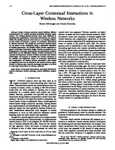
Fig. 1.
DHCP Procedure
the order of seconds [4]. In particular, the longest component of the DHCP assignment procedure is the time between the DHCP DISCOVER sent by the MN and the DHCP OFFER sent by the DHCP server. During this time Duplicate Address Detection (DAD) is performed to be sure that the address the DHCP server wants to offer is not already used by some other MN. According to the DAD procedure, the DHCP server sends ICMP echo requests for the requested address and waits for incoming ICMP echo responses. As of the deployment of Windows XP SP2 the DAD procedure has become less effective since SP2 disables by default any response to incoming ICMP echo requests. In our experiments we have experienced duplicate addresses because of SP2. The delay introduced by the DAD procedure can cause a significant disruption in any on-going VoIP session as well as in any real-time application. Fig. 1 shows the full message exchange between the MN and the DHCP server for acquiring a new IP address. As it will be described in the next section, we introduce the concept of Temporary IP (TEMP IP) as an IP address that can be used by the MN while waiting for the DHCP server to assign it a new IP addresst. The way a TEMP IP is selected, follows some heuristics based on a particular behavior of the DHCP server. In particular, after the DHCP server has assigned all the IP addresses of its pool at least once, it will assign addresses to new clients based on an aging mechanism. The IP address that has not been assigned for the longest time will be assigned first. It is clear how, after some time, the way the IP addresses are allocated by the DHCP server is completely random, one exception being that for any given MN the DHCP server will try first to assign the last address that MN used earlier. Because of this randomness in assigning IP addresses, we started measuring the average number of consecutive IP addresses in use in a wireless subnet. As it will be explained more in detail in Section V, in our experiments the number of consecutive IP addresses used at peak time has a 99th percentile value of 5. This means that in 99% of the cases we will have at most 5 consecutive used IP addresses before finding an unused one, our TEMP IP. In a wireless environment it is safe to assume that the degree of mobility of the MNs is high. Because of this, a common situation will be the one where a MN leaves the subnet before
TABLE I E NHANCED L2 CACHE
MAC address Channel Subnet ID
Key AP1 11 160.38.X.1
Best AP AP2 1 128.59.X.1
Next Best AP AP3 6 160.38.X.1
its IP address lease has expired. This means that usually there will be many leases which have not expired, that are not used and cannot be assigned to new MNs. This represents a substantial waste and inefficiency of the IP pool management scheme especially in networks with a high degree of mobility. In our approach we exploit this misbehavior by re-using such IPs so that even though they cannot be assigned by the DHCP server we can still use them as TEMP IP as they would not be used at all otherwise. Furthermore, we also consider a crowded scenario where there are many MNs sleeping. In such a scenario, the IP addresses of the sleeping MNs can be used as TEMP IP for the time needed to acquire a new IP address via DHCP. Please note that normally the TEMP IP is used for a short amount of time, usually on the order of one second, as this is typically the amount of time needed to acquire a new IP address via DHCP. For the application layer handoff we use the SIP protocol. It is important to emphasize that when using a TEMP IP, such an IP is used for ongoing sessions only. The SIP Home Registrar is not aware of the TEMP IP, only the Correspondent Node (CN) is aware of the change of IP for the ongoing session; a new session will be initiated or accepted only after getting a new IP via DHCP. This is done in order to prevent a potential conflict if the TEMP IP used is the IP of a MN in a sleeping state. In the following section we will introduce a new approach for subnet change detection as well as for fast address acquisition via DHCP. B. Algorithm According to the spatial locality principle and to other considerations expressed in the previous section, we use an enhanced version of the cache mechanism introduced in [10]. This allows us to have a L2-assisted L3 handoff. The structure of the enhanced cache is shown in Table I. We now save in the cache the information about the relay agent IP address for each AP. The relay agent IP address is used to identify each subnet and at the same time to associate a particular AP to its subnet. In general, when more than one subnet is present in a network, the relay agents are needed for the DHCP server to identify from which subnet a DHCP REQUEST is coming. This allows the DHCP server to assign a valid IP address to a MN in its subnet. If the network has one subnet only, then there is no need for relay agents, and DHCP REQUESTs will be handled by the DHCP server directly. The DHCP server, in fact, will have to assign IP addresses belonging to its own subnet only.
As we will describe later more in detail, once the MN discovers a new subnet, it saves this information in cache so that the next time it connects to the same AP, it will already know in which subnet it is and no subnet discovery process will have to be initiated. We will now describe the new algorithm more in detail. When a MN performs a L2 handoff and connects to a new AP, it has to check if a subnet change has occurred or not. In order to do this, it first checks its L2 cache to see if it has a valid value in the subnet ID field for the new AP. If it does, the MN compares this value with the subnet ID value of the previous AP and if the two fields have the same value the subnet has not changed. If the values are different, the subnet has changed and the MN has to initiate the L3 handoff process. In this case such a process does not include a subnet discovery phase since the L2 cache already has such information. On the other hand, when the MN performs a L2 handoff and it cannot find a valid value in the subnet ID field of the new AP, it has to initiate the subnet discovery procedure. 1) Subnet Discovery Procedure: The MN sends a bogus DHCP REQUEST to the DHCP server (i.e. requesting the loopback address). The DHCP server responds with a DHCP NACK which includes among other things, the IP address of the relay agent of the subnet the MN is currently connected to. This IP address is the value that will be stored in the Subnet ID field in the L2 cache. Now that we have a valid value for the Subnet ID field we can update the L2 cache and check if we still are in the same subnet or if the subnet has changed by comparing the two subnet ID fields of the current and previous APs. If we are in the same subnet no further action is needed as we have performed a normal L2 handoff. However, if we are in a different subnet, we have to initiate the L3 handoff process. The L3 handoff process changes according to three main scenarios: • Scenario 1: The MN enters in a new subnet for the first time ever. • Scenario 2: The MN enters in a new subnet it has been before and it has an expired lease for that subnet. • Scenario 3: The MN enters in a new subnet it has been before and it still has a valid lease for that subnet. In the first case scenario, the MN needs to select a TEMP IP to use while waiting for an IP assigned via DHCP: 2) TEMP IP Discovery: In order to find a suitable TEMP IP for the new subnet, we select a random IP address starting from the router IP address which usually is the first one in the pool. We then start sending ARP requests in parallel to 10 IP addresses selected in a sequence starting from the random IP address selected before. As discussed in Section IIIA, this will secure us with a TEMP IP since the probability of finding 10 consecutive IP addresses in use is practically zero. In highly congested wireless networks where IP utilization can be very high, we can increase the number of ARP requests sent in order to find a TEMP IP. This larger number of ARP requests does not have any impact on the handoff time as the ARP requests are sent in parallel. In our experiments we have
Fig. 3.
Fig. 2.
SIP Session Update
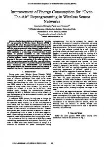
Average IP usage in Columbia University Wireless Network
used an ARP timeout value of 130 ms. As will be explained in Section V.B, this value represents the 90th percentile of the total waiting time in the worst case scenario. The ARP timeout value must be chosen carefully, a bigger value will increase the total handoff time, while a smaller value will introduce a risk for duplicate address. During peak time, in our experiments the number of used IPs was about 50% of the total IP pool (Refer to Fig. 2). By choosing the 90th percentile of the waiting time, the risk of picking an IP address currently in use as TEMP IP at peak time, is about 5%. In situations where the network congestion is higher, a 99th percentile value of the total waiting time should be chosen instead. In the second case scenario the TEMP IP is selected as described above. The only difference is that instead of sending ARP requests starting from a completely random IP address, we start from the IP address we had the last time we were in this subnet. In general, the DHCP server always tries to assign to a MN the same IP address it assigned to that MN the last time it was in that subnet. This makes of the IP we last used in that subnet the perfect candidate for TEMP IP and perhaps the DHCP server will assign that same IP address as well. In the third case scenario there is no need for a TEMP IP since we still have a valid lease for the new subnet. In this case we can start using the IP with the valid lease right away and send a DHCP REQUEST to the DHCP server in order to renew such a lease. 3) SIP Session update (1): Once we have a valid IP to use, we can initiate the L3 handoff at the application layer. In this paper we use SIP. The MN will send a re-INVITE to the CN informing the CN of the change in IP. The CN will reply with an OK. At this point the data exchange can be resumed. Note that the data exchange can be resumed after receiving the OK before receiving the ACK. The full sequence of signals exchanged is shown in Fig. 3. Please note that in scenarios one and two, only the CN is aware of the TEMP IP. The ongoing sessions will not be interrupted while new sessions will be accepted and/or initiated only after getting the new IP address via DHCP. When this
Fig. 4.
Full SIP Session Update
happens a REGISTER will be sent to the SIP Home Proxy to signal the change of IP address. 4) DHCP Address Acquisition: In scenarios one and two, we have to request a new IP address to the DHCP server. This will not cause any interruption because we are now using TEMP IP while waiting for the new IP address. Also, in scenario three this step is not required because we already have an IP address with a valid lease that we can use for the particular subnet we moved into. 5) SIP Session Update (2): As a final step, a new L3 handoff at the application layer is required so that the CN and the SIP Home Proxy are aware of the MNs new IP address. As mentioned before, this time a REGISTER is sent to the SIP Home Proxy so that new sessions can be accepted and/or initiated as well. The full sequence of signals exchanged is shown in Fig. 4. 6) TEMP IP removal: Once the SIP session update has finished, we can then safely remove the TEMP IP and start using the NEW IP assigned by the DHCP server. The switching between TEMP IP and NEW IP is completely seamless. The full handoff process for scenario one is shown in Fig. 5, including the subnet discovery phase. Please note that the sequence of messages exchanged in scenario two and three is a subset of the messages exchanged in scenario one.
Fig. 6.
Fig. 5.
Scenario 1: Handoff Procedure
C. A SIP Presence Approach In the previous section we have described how to perform a L3 handoff by using a TEMP IP. However, such an approach has its weakness in the way the TEMP IP is selected. In particular, the ARP request timeout is the critical parameter. If such a timeout is too long it will directly affect the handoff time, if it is too short it might cause duplicate address if the IP address selected for TEMP IP is already in use. To solve this issue, in this section we introduce an approach for finding a valid TEMP IP based on the SIP presence model. In particular, we call Requesting STA (R-STA) the STA which needs to find a TEMP IP and Assisting STA (A-STA) the STA which will help the R-STA to find such a TEMP IP. We introduce a new presence service in which each subnet is a presentity. Each subnet will have a contact list of all the ASTAs available in that subnet so that the presence information is represented by the available A-STAs in the subnet. When one R-STA subscribes to this service, it will receive presence information about a subnet, namely its contacts which are the available A-STAs in that subnet. Please note that each client can embody both an R-STA and an A-STA. Using this model each A-STA will publish its presence information (URI, status) as contact of the presentity. In particular, for each subnet we will have a contact list of A-STAs available in that subnet at any given moment so that when an R-STA needs to find an A-STA in a particular subnet, it will select it from the contact list of that subnet. The chosen A-STA will then change its status to busy. The R-STA will ask the A-STA to find a valid
The architecture of the fast L3 handoff implementation
TEMP IP in the A-STA subnet. The A-STA will start to send ARP requests to find an unused IP in its subnet (TEMP IP). Once the whole arping procedure has finished and the A-STA has sent the new TEMP IP to the R-STA, the A-STA will change its status back to available. If an A-STA is going to perform a handoff (i.e. is acting as R-STA), it will set its status to unavailable. Please note that this would also allow us to use some of the authentication mechanisms typical of the rich presence framework. Using this approach, the R-STA can obtain a TEMP IP while still in the old subnet which means that choosing a big value for the ARP timeout will not increase the total handoff time. In this way we can be sure to avoid duplicate address and at the same time the TEMP IP discover would not contribute to the total handoff time any longer. In particular, since we know the TEMP IP before the actual handoff, we can think of a scenario where we can update the SIP session before performing the L2 handoff thus further reducing the total L3 handoff time. However, a few considerations are needed in regards to this last scenario. In general, in 802.11 networks there is no way to know in which direction a STA is going to move next. In particular, performing a SIP session update before the L2 handoff can lead to a big penalty if the STA will connect the STA to a different AP than the one for which the SIP session was updated. In such a case the STA would have to restore a L3 session starting all over. A possible solution to this problem might be to send a probe frame to one of the next APs so that from the signal level we can try to guess to which AP we are moving closer to and therefore, will perform the handoff to. The SIP presence approach introduced in the present section is much more reliable than the approach introduced in the previous section for TEMP IP discovery. We have to keep in mind, however, that the SIP presence approach requires significant support on the network side whereas the TEMP IP discovery proposed in the previous section does not require any network support at all. IV. I MPLEMENTATION To implement our L3 handoff approach, we had to modify a DHCP client, a wireless card driver and a SIP client. We selected Linux as a platform because we could easily get the source code of a DHCP client and a wireless card driver. We used dhcp-pl2[12] as a DHCP client, HostAP driver (hostap0.0.4)[13] as a wireless card driver, and a SIP client from SIPquest [14].
IP
TABLE II DHCP AND OUR NEW APPROACH
ACQUISITION TIME IN NORMAL
Lease is expired Lease is not expired
Fig. 7.
Experimental environment
V. E XPERIMENTS A. Test Environment We performed the experiments on the 7th floor of the CEPSR Building in Columbia University. Since the Columbia University wireless network has only one subnet (160.38.x.x) as we mentioned in Section III-A, we setup an extra AP to add the second subnet (128.59.x.x). We used the two subnets for testing our new L3 handoff approach. We used a Pentium IV 2.4GHz Desktop with Windows XP as a static node and installed SIPc [15], a SIP client from Columbia University. As a mobile node, a modified version of the SIP client from SIPquest was used in an IBM ThinkPad Pentium III with RedHat 9.0 (kernel version 2.4.20). B. Parameter Calculation In order to get an optimal waiting time value for ARP responses, we sent ARP requests to IPs from 168.38.244.1 to 168.38.246.255 and measured the response times. These are the most frequently used IP addresses in the Columbia University wireless network. In order to check the worst case scenario, we performed these experiments during the time of maximum network congestion (between 3:00PM and 4:00PM). We found that the 90th percentile value of the minimum waiting ARP time for detecting an IP address as in use, was 130 ms, and the 99th percentile value was 260 ms. We also calculated the number of IPs consecutively used in the DHCP IP pool finding a 99th percentile value of 5. C. Measurements Theoretically, the L3 handoff time is the time from the L2 association response frame to the binding of the new IP address. However, in SIP, after getting an IP address, the mobile node needs to announce its new IP address to the CN. Normal communication will be disrupted until the CN updates its session with the new IP. Therefore, we defined the L3 handoff time as the time from the L2 association response frame to the SIP OK message after which normal communication resumes. In order to measure the L3 handoff time, we needed to capture the L2 association response frame and the SIP OK message. To capture all the packets from and to the mobile node including the L2 association response
Normal DHCP 518 ms 7.5 ms
Using temp IP 108 ms 1 ms
frame, we used Kismet[16] as wireless sniffer. To capture all the SIP messages in the static node, we used Ethereal[17]. We measured the packet loss during the L3 handoff. We defined the packet loss as the number of packets sent from the CN between the L2 association response frame and the SIP OK message, according to the definition of L3 handoff given earlier. Since the CN captures every RTP packet, we just needed to know exactly when the L2 association frame had been received, and count the number of packets sent between that point in time until when the SIP OK message had been sent. We synchronized the CN and the sniffer using the Network Time Protocol (NTP), and used the arrival time of the L2 association frame captured in the sniffer to calculate the packet loss. D. Experimental Results 1) IP Acquisition Time: Table II presents the average IP acquisition time for the standard DHCP procedure and for our new approach. In the standard DHCP, when the DHCP client needs to get an IP address, it checks the lease file. The lease file contains IP addresses, their lease time and the subnet information. If the lease has expired, it sends a DHCP DISCOVER packet to get a new IP, otherwise, if the lease is still valid, it sends a DHCP REQUEST packet to renew the leased IP address [11]. According to our results, we can see that it takes more than 500 ms in average to get the new IP via DHCP. This is mostly because of DAD. Actually, the standard implementation should use 1 sec waiting time for an ICMP response, but we have found out that the waiting time changes randomly from 10 ms to 900 ms because of an architectural flaw in the Internet System Consortium (ISC) implementation. When the lease has not yet expired, it takes less than 10 ms in average to renew it and the DHCP client binds to the IP address only after it gets a DHCP ACK from the DHCP server. In our approach, we first bind to the leased IP and we then start the process for renewing it, in this way we have a disruption of less than 1 ms. Fig. 8 shows the total L3 handoff time and Fig. 9 presents all the components of the L3 handoff time for an ARP response in the worst case scenario. We have divided the L3 handoff time into four components: Subnet detection time, IP acquisition time, Client processing time and SIP signaling time required for updating SIP session. We measured the whole L3 handoff time in the three scenarios specified in Section III-B, took the average of each component, and reconstructed the total L3 handoff time of each scenario. The definition of each component is as follows: • Subnet detection time: From the L2 association response frame to the DHCP NAK frame of the bogus
Fig. 10.
Fig. 8. L3 handoff time using SIP (average). Comparison between current approach and proposed approach (Scenarios 1, 2, 3)
Packet loss during L3 handoff (average)
the one shown in Fig. 10. However, the burstiness of the packets caused the packet loss to be slightly bigger. VI. C ONCLUSIONS AND FUTURE WORK
Fig. 9.
Scenario 1: L3 handoff components and their delay
DHCP REQUEST. IP acquisition time: From the sending the first ARP request to expiration of the ARP response waiting timer. • SIP signaling Time: From when the INVITE message has been sent by the MN to when the OK message has been received by the MN. • Client processing time: the gap between components for processing internal signals etc. As we can see in Fig. 8, by using the proposed approach the L3 handoff takes 200 ms, 170 ms and 30 ms in scenario 1, scenario 2 and scenario 3 (Section III-B.1) respectively, while it takes about 580 ms with the legacy approach. In order to compare the two approaches, we have used our subnet detection mechanism also when measuring the L3 handoff delay in the legacy approach as there are currently no other mechanisms to do this in a timely manner. 2) Packet loss: Fig. 10 shows the packet loss during L3 handoffs. From Figs. 8 and 10 we can see that the number of packets lost is roughly linear with the handoff time, as we expected. We used a packetization interval of 20 ms. Using such a value, we would have expected lower packet loss than •
In this paper, we have introduced a novel L3 handoff approach. In our approach, in order to detect subnet changes, we send a bogus DHCP REQUEST which will cause the DHCP server to send a DHCP NAK. We then extract the relay agent information from the DHCP NAK frame. A Temporary IP address is selected by sending ARP requests to an IP range to find an unused IP address. The TEMP IP will be used until a DHCP server assigns a new IP address to the MN. In such scenario, the L3 handoff takes about 190 ms. Even though this does not make the handoff seamless, it represents a big improvement considering that there is no L3 handoff approach in the current Linux kernel and that such a delay is more than 40 s in Windows XP. When a MN has already visited the new subnet once before and the lease for such subnet has not yet expired, the MN can update its SIP session with the IP address first and renew the lease later, achieving a seamless handoff with the delay of about 30 ms. Note that in such a scenario only a renew of a valid lease is required. One of the requirements of our approach was to not require any infrastructure changes. All the changes required by our new approach are introduced on the client side. Only mobile nodes (wireless card driver and DHCP client) need to be modified, and this makes our solution more practical. However, not introducing changes on the infrastructure side forced us to introduce some tradeoffs between the total handoff delay and the duplicated address probability. There is a small chance to get a duplicated IP address as a TEMP IP due to long response times of ARP responses in a Wireless Network. In order to solve such a problem and make the TEMP IP solution more reliable, in Section III-C we introduced a new approach based on the SIP presence model for determining the correct TEMP IP. In particular, with the help of other STAs we are able to find a TEMP IP with no time constraints without adding to the total handoff time and therefore reducing to zero the risk of having a duplicate IP address.
As explained in section V, the biggest contribution to the DHCP delay is given by the DAD procedure. We have already started to work on avoiding duplicated IP addresses without using any explicit DAD procedure. In doing so, it will be possible to acquire a new IP from the DHCP server in a few milliseconds, which will allow to further reduce the L3 handoff time. R EFERENCES [1] J. Rosenberg, H. Schulzrinne, G. Camarillo, A. R. Johnston, J. Peterson, R. Sparks, M. Handley, and E. Schooler, “SIP: session initiation protocol,” Internet Engineering Task Force, RFC 3261, June 2002. [2] W. Kim, M. Kim, K. Lee, C. Yu, and B. Lee, “Link layer sssisted mobility support using SIP for real-time multimedia communications,” in MobiWac ’04: Proceedings of the second international workshop on Mobility management & wireless access protocols. New York, NY, USA: ACM Press, 2004, pp. 127–129. [3] A. M. et al., “Dynamic Registration and Configuration Protocol (DRCP),” Internet Engineering Task Force,” Internet Draft, July 2000. [4] N. Akhtar, M. Georgiades, C. Politis, and R. Tafazolli, “SIP-based end system mobility solution for all-IP infrastructures,” in IST Mobile & Wireless Communications Summit 2003, june 2003. [5] D. Vali, S. Paskalis, A. Kaloxylos, and L. Merakos, “A SIP-based method for intra-domain handoffs,” Vehicular Technology Conference, 2003, vol. 3, pp. 2068–2072, 2003. [6] A. Dutta, S. Madhanie, W. Chen, O. Altintas, and H. Schulzrinne, “Mobicom poster: optimized fast-handoff schemes for application layer mobility management,” SIGMOBILE Mob. Comput. Commun. Rev., vol. 7, no. 1, pp. 17–19, 2003. [7] R. Hsieh, Z. G. Zhou, and A. Seneviratne, “S-mip: A seamless handoff architecture for mobile ip.” in INFOCOM, 2003. [8] D. V. Ote, “A sip-based method for intra-domain handoffs.” [Online]. Available: citeseer.csail.mit.edu/658563.html [9] H. Yokota, A. Idoue, T. Hasegawa, and T. Kato, “Link layer assisted mobile ip fast handoff method over wireless lan networks,” in MobiCom ’02: Proceedings of the 8th annual international conference on Mobile computing and networking. New York, NY, USA: ACM Press, 2002, pp. 131–139. [10] S. Shin, A. G. Forte, A. S. Rawat, and H. Schulzrinne, “Reducing MAC layer handoff latency in IEEE 802.11 wireless LANs,” in MobiWac ’04: Proceedings of the second international workshop on Mobility management & wireless access protocols. New York, NY, USA: ACM Press, 2004, pp. 19–26. [11] R. E. Droms, “Dynamic Host Configuration Protocol (DHCP),” Internet Engineering Task Force, RFC 2131, Mar. 1997. [12] I. S. Consortium, “Dynamic Host Configuration Protocol (DHCP).” [Online]. Available: http://www.isc.org/index.pl?/sw/dhcp/ [13] J. Malinen, “Host AP driver for intersil prism2/2.5/3.” [Online]. Available: http://hostap.epitest.fi/ [14] “SIPquest Inc.” [Online]. Available: http://www.sipquest.com [15] C. University, “Columbia sip user agent (sipc).” [Online]. Available: http://www.cs.columbia.edu/IRT/sipc [16] “Kismet.” [Online]. Available: http://www.kismetwireless.net [17] “Ethereal Network Protocol Analyzer.” [Online]. Available: http://www.ethereal.com