Ironically, however, network management software has .... business. In most cases, availability is based on the reliability of individual ... (MAC) addresses.
ECOLOGICAL INTERFACE DESIGN: A NEW APPROACH FOR VISUALIZING NETWORK MANAGEMENT Catherine M. Burns Johnson Kuo Sylvia Ng Advanced Interface Design Lab Department of Systems Design Engineering University of Waterloo N2L 3G1
Correspondence should be addressed to Catherine Burns, Advanced Interface Design Lab, Department of Systems Design Engineering, University of Waterloo, 200 University Ave W, Waterloo Ontario, N2L 3G1
Keywords: network management, interface design, visualization, problem-solving
ABSTRACT Effective network management is a key to maximizing the performance of today’s networks. Active monitoring of networks is still largely the domain of human network managers and yet, the support tools provided to these operators are typically not integrated and dated in their interface design. EID is a systematic approach, drawn from nuclear power plant control, for designing visualizations that uses a multi-level analysis to develop graphics designed to support problem-solving and management activities. We demonstrate the adaptation of this approach to network management and show how visualization tools can be designed. Finally we evaluated the EID tool against an industry tool, HPOpenView Network Node Manager in a series of detection and diagnosis tasks. While we observed slightly faster detection times with Network Node Manager, the EID tool generated faster diagnosis times and more accurate diagnoses. Finally we took our tool to professional network managers for a qualitative evaluation.
INTRODUCTION Effective network management is critical to the operations of today’s businesses and organizations. Network equipment has increased dramatically in capacity, performance, and diversity. Ironically, however, network management software has generally not kept pace. In most cases, management software is specific to one type and manufacturer of equipment, meaning that network managers must use many small customized software tools. Over-arching network management tools are limited in the kind of information that they collect, and even more, limited in their graphical approaches for displaying that information. This limitation in tools makes network management a difficult task that requires high levels of experience and problem-solving skills. Network managers must monitor networks that consist of a diverse collection of equipment with widely varying capabilities (some of it legacy equipment) and disjoint tools that were not designed to aid problem-solving. Furthermore, this work must be done in a networked environment that is steadily increasing not only in normal traffic but also in threats to its security and proper operation. It is time that network management and the design of network management software received some of the design attention that has been granted to other areas of network development. In the early days of networking, traffic levels were low and networks were the domain of academics who could afford to be tolerant of network problems. Those days have changed and computer networks are now a critical part of our economic infrastructure. Slow response times, networks that are down, and security threats like “denial of service” attacks result in real and significant costs. The diversity of networking equipment and the unpredictable creativity of people who “hack” into
networks means that automated solutions are not likely to ever be completely successful. There will always be a need for human network managers. In order to tackle the problem of how to design network management displays that will more effectively aid network managers in solving a variety of network problems, we took guidance from other domains that are also complex, operation-critical, and reliant on human problem-solving. In particular, we adapted an approach that was developed from the domain of nuclear power plants that has been used successfully to design displays for power plants [11], petrochemical plants [6], biomedical applications [4], and aviation displays [3]. This approach is called Ecological Interface Design (EID) and is a particularly promising new approach for network management software. We developed an EID tool for network management and then evaluated it against an industry level network management tool, HPOpenView. In the following sections we discuss the theory behind ecological interface design and our development of an EID tool for network management. Then we present the results of our evaluation. Finally we conclude with some qualitative comments made by professional network managers. Ecological Interface Design EID evolved from a control systems perspective on human performance [7]. Rasmussen [7] studied electronics troubleshooters as they solved different problems and used his observations of problem-solving activity to develop an approach for designing tools for aiding problem-solving. His approach originated from the idea that people use their understanding of how a system works in order to manage and diagnose problems with a system. Furthermore, this knowledge of how a system works can be modeled and used to develop new human-computer interfaces that will help operators understand the
system that they are controlling. This perspective is distinctly different from the traditional Human-Computer Interaction (HCI) or User-Centered Design (UCD) perspectives which begin by focusing on the user and attempt to identify information that is needed to complete only certain well-defined tasks. In contrast, the EID perspective advocates that the system must be understood first, and then displayed in a way that is useful for the user. In this way, the display can help the user navigate through the system and solve problems even in unanticipated situations. In comparison with other approaches to interface design, an interface designed using EID can be expected to demonstrate the following benefits: 1.
from the model of how the system works, critical information for the displays can be identified. EID displays typically show more information than other displays and this additional information is needed for effective problem-solving.
2.
from the structure of the model, a map of the display architecture can be derived, identifying overall system view information from lower level detailed information
3.
operators using an EID typically demonstrate faster and more accurate problem diagnosis behaviour
EID, therefore, begins with the creation of a work domain model, which is a fivelevel hierarchical description of how the system works. This model is then used to develop information requirements that are used in interface design. To our knowledge, this is the first structured approach to the design of network management software that we have seen reported in the literature.
A WORK DOMAIN MODEL FOR NETWORK MANAGEMENT In our study, we used a portion of our university’s campus network, in particular, the University of Waterloo Village 1 Residence network, as our network model upon which to demonstrate the principles of EID in the network management domain. This network provides Internet connections for 1313 residence rooms in the Village 1 residence complex and is composed of about 65 Ethernet switches that are centrally tied to main switch and router module, which in turn connects to the main backbone switches on campus. This particular network was chosen, as it is sufficiently large to demonstrate several important display design concepts in network performance management using the EID approach without being overly complicated. We developed a work domain model for this network using the approach of Rasmussen [7]. In this five level model, each level of the hierarchy describes the same system using a different level of description or functional model for observing the system [10]. In addition, these levels are related via a structural means-end relationship, and are arranged such that the purpose or ends of the system are located near the top of the hierarchy, while the means by which these ends are achieved are found in the lower levels. The top level, referred to as Functional Purpose, provides an overall view with respect to the purpose for which the system was designed. The second level, termed the Abstract Function level, deals with physical laws and the causal structure of the process, such as mass, energy or information flow. The third level, representing Generalized Functions, is concerned mainly with the physical processes by which the abstract functions are achieved but without reference to physical implementation. The fourth
level, the Physical Function layer, describes the capabilities and interconnections of the components of the system. Finally, the lowest level of abstraction, the Physical Form, describes only the physical appearance and condition of components and their locations within the overall structure of the system. These different levels of the abstraction hierarchy are interconnected to show the relationships and links between the higher levels (i.e. purpose of the system) and the lower levels (i.e. physical implementation). Generally, the reason for representing domain information in a work domain model is so that operators can develop a deeper understanding of their work environment by examining different variables in the system and seeing how they relate vertically across the various levels. For example, by moving up the hierarchy, operators can gain a deeper understanding of how various components interact to meet system goals, while moving down the hierarchy reveals the means by which these goals are carried out. By structuring information in this way, an operator can determine the answer to why a certain component exists by examining the level above and seeing what goals or purpose it serves. Similarly, one can determine how a component is implemented by examining the level below. This analysis is typically repeated at different levels of detail (i.e. system, subsystem, and component). In adapting the approach to network management, we applied the analysis at different levels of the communications layer hierarchy. The communications layers represented within our analysis include the Application Layer, the Network Layer, the Data Link Layer, and finally, the Physical Layer. The last three layers map directly to the corresponding layers of the OSI Reference Model, while the top layer encompasses the Transport, Session, Presentation, and Application layers of the
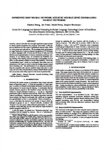
OSI model and is simply referred to as the Application Layer in this analysis. This was done because the top four layers of the OSI model all deal with end-user communications, and unlike the bottom three layers, the protocols used at the upper layers can vary significantly depending on the type of network used [5]. Thus, to simplify the analysis, all four layers were grouped into one layer to represent application performance at the end-user level. We developed a grid model using the two hierarchies: Rasmussen’s means-end hierarchy on the vertical dimension and the communications hierarchy on the horizontal dimension. 1 Figure 1 shows these dimensions and our work domain model at a fairly low level of detail. The following sections describe the contents of the model in more detail.
1
The orthogonal arrangement of the state space does not necessarily imply that the two
dimensions used are conceptually orthogonal, however.
FP
Data Link
Network
Application
Physical
Maximize Availability Maximize throughput of communications between distributed applications
Maximize Accuracy
Minimize Errors
Minimize Delay
AF
LAN Traffic
Internetwork Traffic Data Sink
Data Source
Reliable Data Transfer Between Devices Within a LAN
Data Transfer Between Networks
GF Internetwork Traffic Routing
Broadcast Containment
Traffic Prioritization
Signal Source
Data Sink
Data Source
Signal Sink
Signal Transmission Across Physical Medium
Network Segmentation
Error Checking
Packet Switching
Packet Retransmission
Signal Generation
Signal Propagation
Collision Detection
PFn Routers
Switches
Bridges
Hosts
Network Interface Card
Cable
PFo Network Topology
Physical Form of Device (e.g. # of ports)
Physical Location of Device
Cable Form (e.g. twisted pair, coaxial)
Figure 1. Work Domain Representation for Network Performance Management.
Functional Purpose The Functional Purpose (FP) of a computer network is to provide a reliable and efficient means of communicating information between distributed applications and devices. Modern data communication networks are often composed of many and varied components, which must intercommunicate and share data and resources. In some cases, it is critical to the effectiveness of an application that communication over the network is within certain performance limits. Time-sensitive applications, such as video-
conferencing software, for example, are particularly dependent upon the ability of the underlying network to deliver and receive large amounts of data in a timely manner in order to function effectively. Consequently, at the Application Layer, it is clear that the primary objective is to maximize the throughput of communications between applications in a distributed environment. That is, application data from one host must somehow be delivered expeditiously to another host requesting this information in order to provide satisfactory application performance. Thus, the greater the throughput of data among distributed applications, the more data can be transferred in a given amount of time, which ultimately leads to increased satisfaction among end-users of the network. At the Network Layer, this objective can be expressed in terms of maximizing the availability of the network, maximizing and ensuring accuracy of data delivered, and minimizing the response time between when a request is issued to when a reply is received by a host. Availability can be expressed as the percentage of time that a network system, component, or application is “up” or available to an end-user [9]. In many cases, the cost of down time can result in tens of thousands of dollars per hour in lost productivity and business. In most cases, availability is based on the reliability of individual components in a network as well as the organization of the system. For example, some components may be redundant such that the failure of a component may lead to reduced capacity or capability, but the overall system is still able to function. Accuracy of data being transmitted among network devices is also another objective and is essential for any communications system. However, because of built-in error correction mechanisms supplied by various protocols in the Data Link Layer,
accuracy in data transmission is generally not a concern for the end-user. Nevertheless, excessive errors in a network may be a result of an intermittently faulty line or some source of interference, and may have an impact on network performance due to the need for increased retransmissions. As a result, one of the main objectives identified at the Data Link Layer is to minimize errors in transmission among devices so that the accuracy of data transferred across the network at the Network Layer is maximized. Minimizing response time is thus concerned with searching for, identifying, and eliminating the potential processing and communication bottlenecks that contribute significantly to the overall time taken between sending a request and receiving a response through the network. For the purposes of structuring and understanding the work domain, the functional purpose of a communications network is described in terms of what the outputs of the system should be. In this case, the goal of maximizing throughput of communications among distributed devices at the Application Layer, and maximizing availability and accuracy, as well as minimizing response time at the Network Level provides a framework for structuring the rest of the elements in the work domain. By moving down through the various levels of the hierarchy from here, one can observe how each of the important objectives in the work domain are achieved through progressively more concrete representations or views of the same system. Abstract Function The Abstract Function (AF) level provides a view of the causal structure of the system. At this level, the network could be described in terms of information flow from one point to another. Information is generated at some source, representing the originator
or sender of the information, and is transferred through some medium to the intended recipient, or sink for that information. The transfer mechanism must ensure that there are available paths to connect the source and sinks of the information flow. The implication of this design is that information is preserved or “conserved” as it travels through the communications medium. While this conservation principle has a different meaning than that applied to mass and energy flow systems in most physical systems, it is nevertheless useful to describe communications networks in these terms. Just as conservation of mass and energy would apply to physical, closed-loop systems, conservation of information needs to take place in order for a communications through a network to operate correctly. For example, information that is generated by a certain device (or source) and specifically intended for another device (or sink) must be transferred through the network to its destination without loss or modification to the original data. If the information from this source were somehow changed or misdirected to a host other than the intended recipient, then the conservation of information principle would be violated, since a loss of information has occurred between the source and sink. As shown in Figure 1, the concept of information conservation can be applied at various layers of the communications part-whole hierarchy. At the Network Layer, communications through the system is viewed at the level of internetwork traffic or traffic that travels between different LANs or broadcast domains. As such, sources and sinks at this layer are described in terms of logical addresses, such as IP addresses. At the Data Link Layer, however, communications is viewed at the level of traffic within a LAN, and sources and sinks are described in terms of physical media access control (MAC) addresses. Whereas the Network Layer provides a view of the system with
respect to the flows of information through the network as a whole, the Data Link Layer deals mostly with flow of data through individual network devices or resources within a LAN. Moving down to the Physical Layer, one can view the system as the transfer of signals along a physical medium between the device generating the signals (i.e. the source) to the device receiving and interpreting them in another location (i.e. the sink). Thus, the level of description changes from internetwork traffic flow at the Network Layer to intra-LAN traffic flow at the Data Link Layer and finally to bit-stream data flow along a wire at the Physical Layer. Regardless of the communication layer or level of description used, however, the principle of information conservation applies in each case. While information is conserved at each layer of the communications hierarchy, it is important to also realize that at each layer of the communications hierarchy, information is conserved as it is transferred between end points. For instance, the information that is sent out at the Application layer from Host A will arrive at the same layer on Host B unchanged and in its original form. Similarly, the information that is sent out at the Network Layer from Host A will arrive intact at the same layer on Host B. The same concept applies to all other layers of the communications hierarchy. Although the information that is acted upon at each layer is different, with application data at the Application Layer and logical network addresses on the Network Layer for example, the information is always preserved within any given layer. Thus, the conservation of information principle can be applied to all layers of the communications hierarchy at the Abstract Function level. In terms of network performance considerations, the abstract functions could be described in terms of resource utilization, which refers to the percentage of time that a
resource is in use over a given period of time [9]. With this notion comes the concept that any network resource, whether it is a network device or link, has a fixed capacity or maximum load limit that it can handle. As network traffic or load increases, the percentage of time needed by a network resource to process or handle the load also increases, thus increasing the level of utilization of the resource. When the load reaches the maximum capacity, the utilization level is at 100% and the resource has reached its limit in terms of the amount of traffic it can handle. Network performance is thus, ultimately limited by the capacity of the network’s individual resources and the closer these utilization levels approach maximum values, the greater the need to provide more capacity to adequately handle the traffic load. It is therefore critical that utilization levels of various network resources be monitored very closely in order to keep network response time to an acceptable level. Thus, as a measure of the health of a particular LAN segment at the Data Link Layer, the utilization levels of each link and switching device can be assessed. At the Network Layer, the distribution of traffic between different LAN segments needs to be taken into account. Here, the relationship between traffic or system load and response time imposes a constraint on how network resources need to be allocated in order to satisfy the objective at the Functional Purpose level. In other words, in order to minimize response time of the overall network, it is necessary to look at how resources are allocated or balanced with respect to the actual traffic load that occurs in different parts of the network. By looking at a profile of how much traffic is flowing within each LAN and between different LANs, it is possible to identify whether the available network resources are allocated efficiently. For example, if it is determined that a certain server is
being mostly accessed from a LAN other than the one it is currently in and as a consequence, an excessive amount of internetwork traffic is being generated, then this would be an indication that the server needs to be reallocated to a more appropriate LAN. Thus, one of the ways of ensuring efficient network operation is to adjust the allocation of network resources such that a larger proportion of the traffic is kept local within a LAN and the amount of traffic between different LANs is balanced [9]. As long as such a balance exists and the total capacity of all resources within the network is able to accommodate the total load of traffic at any given time, the objective of minimizing response time across the entire network can be achieved. At this point, it is instructive to point out how the abstraction hierarchy representation naturally supports goal-oriented problem solving behavior. By moving up the abstraction hierarchy to the functional purpose level, for instance, one can answer the question of why reducing resource utilization and having a proper balance of traffic between different LANs are important: to ensure acceptable performance and response time within the overall network. Similarly, by moving down a level to the generalized function layer, one can answer the question of how these functions are achieved. The processes that support the functions at the abstract layer are discussed in the following section. Generalized Function At the Generalized Function (GF) level, the representation of the work domain changes to a view of the processes by which the abstract functions are carried out. For example, at the Network Layer, the function of moving information through an interconnection of pathways from source to sink is achieved through the traffic routing
process of the underlying system. Since multiple paths may be available in transferring information from one point to another, the performance of a network will be mainly dependent on how efficiently the traffic is routed through to its destination, given the current traffic load on the system. By intelligently routing the information through less busy pathways, a better balance between traffic load and available resource capacity may be achieved, thus maintaining high network efficiency at the abstract function level. Provisions may also be made at the Network Layer for high-priority traffic, such as video-conferencing data, which are highly sensitive to delays in transmission and delivery. In such cases, traffic prioritization mechanisms can be used to maintain acceptable performance for network applications with higher quality-of-service (QoS) requirements by ensuring that high-priority information always goes over the fastest network paths. At the Data Link Layer, the view of the domain is focused on the processes that support the transfer of data from device to device in a LAN, segmentation, framing, and switching. One of the primary measures at this level is transmission delay. Another process that is required at the Data Link Layer in order to satisfy the functional purpose of minimizing errors and ensuring accuracy of data transmission is error checking. This is done through a variety of error-detection protocols. At the Physical Layer, the view of the network changes to the processes that occur at the signal level. Signals are physical changes in voltages along a transmission medium that carry data. Correct data can only be interpreted from a signal, however, if the signal is of a certain form with respect to the timing and magnitude of the waveforms. If the signal’s magnitudes are not great enough or its frequency is shifted either higher or lower
due to loss, distortion, or noise then the data stream may not be interpreted correctly, resulting in error or data loss. As a result, most of the processes at this level are concerned with correct signal generation and propagation, as well as collision detection. Physical Function The Physical Function (PFn) level deals with the actual components and physical implementations of the processes described above. These include the actual physical routers, switches, bridges, hubs and cables that comprise the network infrastructure. The objects described at this layer of the abstraction hierarchy tell how the general network processes in the layer above are actually implemented. Error checking and correction is another process identified at the Generalized Function level that is handled by all hosts and switching devices at the Data Link Layer. Through the implementation of Data Link Layer protocols, all network devices can support error checking, as well as packet retransmission or error correction to ensure reliable transfer of information between devices on a LAN. Similarly, generalized functions at the Physical Layer, such as signal generation and detection, are accomplished using network interface cards (NICs). Since signals tend to degenerate or lose their original form when transmitted over long distances, repeaters may be necessary to boost or regenerate signals so as to maintain signal strength and quality throughout the network. To summarize, views of the domain at the Physical Function level in the abstraction hierarchy are typically concerned not only with the specific types of equipment that exist in the system, but also with the kinds of capabilities that are provided to support the processes described at the Generalized Function level. Many of
the limitations of these processes are due to the capabilities of devices used as well as the specific network configurations that have been implemented. Thus, an analysis of the work domain with respect to performance considerations at the Physical Function level should focus on the speed and capacity of individual devices and components within the network as well as how they are connected or configured to satisfy overall performance requirements. Physical Form At the physical form (PFo) level, components in the domain are described with respect to their appearance, location, and physical condition. This will include, for instance, the network topology and the relative geographic locations of devices that comprise the network. Such information is extremely important to a network manager who for example, will need to quickly locate failed network components and perhaps visually inspect them to determine whether they need to be replaced based on their physical appearance or condition. In addition, network managers may need to quickly assess the physical capacity of individual equipment, such as the number of available ports in a switch, to determine whether or not excess equipment or other configurations need to be implemented when traffic patterns or the number of users and hosts changes.
DERIVATION OF INFORMATION REQUIREMENTS FROM THE WORK DOMAIN MODEL As stated earlier, the purpose of creating a work domain model is to extract information requirements that will be useful for visualization design when developing
effective displays for managing networks. Following the model, we have summarized some of these requirements in Table 1. Table 1. Information requirements derived from the work domain model.
Abstraction Level Functional Purpose
Abstract Function
Generalized Function
Physical Function
Physical Form
Information Requirements Performance target view latency or overall response times accuracy of information transmitted (usually not a problem) availability of network resources throughput of application data through the network threshold settings Information flow view path availability between different LANs traffic load and capacity on each LAN segment balance of information flow within and between different LANs resource utilization of individual links and devices Routing and switching process view traffic routing information broadcast containment areas rate of collisions and errors in different LAN segments Equipment View information on capabilities, capacities, settings, and configuration of network devices Topological View physical location of equipment logical connections between network devices
INTERFACE DESIGN Following the analysis and derivation of information requirements, the next step was to use those requirements to design visualizations of the network. We proceeded systematically through each level, ensuring that the variables from that level were displayed. For graphical visualizations of the variables, we adapted some previously tested and successful visual techniques from other domains. After drawing up the graphical representations of all the variables and components resulting from the analysis on paper, and going through several revisions with various graphical ideas, a working prototype interface was implemented in Visual C++ using the OpenGL library to render
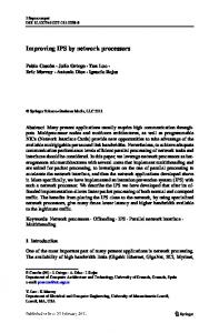
objects in a 3D environment. The resulting application was a fully interactive environment, in which users can navigate to different parts of a network, select different objects of interest, and analyze resulting graphs and information provided. Thus, this prototype tool allowed us to demonstrate the effectiveness of the graphical concepts and ideas in a dynamic way. Since the purpose of the prototype was mainly to test the interface design ideas and not to create a fully functional network management tool, the actual data used to drive the display were simulated but modeled to reflect the traffic patterns of the chosen network as accurately as possible. The following sections provide a description of the prototype display at each level of the abstraction hierarchy used in the analysis. Functional Purpose Display Functional purpose displays are typically overview displays that show system performance against various objectives. An overview of system state should remain continuously visible and allow the network manager to quickly identify network failures in any region of the network. We made our overview display a dedicated view in the top left hand corner of the display (shown in Figure 2). This view presents a 2D image of the topological layout of all the switches and routers in the network. Each device appears symbolically as a colored dot on the overview map, with the colors corresponding to the condition or state of the device at any moment in time (green – normal, yellow – warning, red – critical). The network manager, depending on the normal operating characteristics of the network, can set the threshold levels for these categories. Additionally, bright white-colored dots indicate that the corresponding device is either down or not responding to any requests. This display, with its multitude of dots uses a large amount
of individual data to show overall system state and is an implementation of what is called a “Mass Data Display” (MDD) [12]. MDDs have been shown to be very effective at supporting rapid fault detection and capitalizing on human pattern recognition skills. These dots implement the threshold settings, resource availability, and at a high level, show the performance levels of the devices in the network, implementing the functional purpose level. A trending bar graph is shown below the display (in Figure 2) to show network performance over time. The bar graph is stacked such that its height is determined by the sum of the number of devices that are currently in the “warning”, “critical”, and “down” states. Consequently, a network operator can quickly tell how healthy the state of the network is or has been by observing the height of the bar graph. The taller the bars of the graph, the less healthy state the network is currently in, thus alerting the network manager that there may be potential problems occurring at the moment.
Figure 2. Two close-up shots of the overview map. The left shot is that of a relatively healthy network while the one to the right depicts a less healthy one.
The overview map provides more than just monitoring purposes. It was also designed to serve as a navigation aid for the main 3D view (Figure 3). By positioning the mouse pointer and selecting a point on the overview map, the main view will immediately jump to the corresponding area of the network. In addition, the selected area is highlighted on the overview map, thus providing orientation information to the network manager. Abstract Function Display As discussed above, the abstract function level deals with information flow from one area of the network to another. The information must be generated at some source and then transferred over a network of links and devices to its intended destination or “sink” for that information. Since there are numerous sources and sinks within a network and a limited number of links with set capacities, each device on the network must share the available bandwidth with other devices that may be transmitting information at the same time. For example, if a large number of devices were attempting to transmit information on a particular link, the utilization levels along that link may quickly approach its available capacity for handling traffic, thus resulting in excessive congestion and a decrease in data transfer rate for each device using that link. Thus, an important measure of network performance is link utilization, as this measure directly affects how quickly information can be transferred from one point to another. It is also important for the network manager to know how utilization levels are distributed across the entire network not only for each physical link but also for logical links that connect between different LANs or VLANs. Because there is some delay
associated with routing traffic from one LAN to another, it is important to keep as much of the traffic local within a LAN as possible in order to minimize the amount of traffic that needs to pass through a router. Thus, by examining a profile of how much traffic is flowing between different LANs as well as within each LAN, a network manager may be able to determine if network resources are allocated efficiently and whether the capacities of certain links may need to be upgraded to allow for more balanced utilization. Response time throughout the network can only be minimized if all links are carrying a proportionate share of the traffic load. Figure 3 shows a screenshot that allows the network manager to quickly extract information concerning the utilization of links both within and between different VLANs.
Figure 3. Logical view of residence network in Visual Network, showing traffic levels between and within different VLANs.
The view shown in the figure represents a logical view of the network, where switches that are logically assigned to one VLAN are physically placed together in a circle in one area, and each area is linked to every other area to represent the logical connections between them. In addition, logical links are shown between each switch and every other switch within the same VLAN to give an indication of the level of intra-LAN communications. When the traffic load is light and utilization levels are low, the links appear with a dull green color. However, when the levels cross a warning threshold, which signifies that the amount of traffic is starting to significantly affect the data transfer rate through that link, the link will turn yellow. Links turn a salient red when it is nearly saturated with high amounts of traffic that result in severe network congestion and delays in transmission. To aid in determining the traffic load that flows across the network between different LANs or VLANs, a utilization matrix is shown in the lower right hand corner of the display. This display allows the network manager to quickly get a feel for where the traffic load is heaviest and what the distribution of the load is like between each pair of VLANs. In the “combined” mode, the display appears as a matrix with only its lower diagonal area filled in by a set of colors that match the colors of the corresponding links in the main view. Each cell of the matrix thus represents the combined level of traffic that is flowing in both directions between the two VLANs represented by the identifier in both the row and column of the matrix. In Figure 3, for example, there is a single link that shows a critical amount of traffic flowing between VLAN 33 and 39, which is
represented in the matrix as a red square located at the column labeled 33 and the row labeled 39. All other inter-VLAN links are operating in the normal range, so the other cells in the lower diagonal of the matrix show a green color. In the “split” mode, the matrix has all of its cells filled in with color except for the cells along the diagonal. Here the traffic is “split” to represent both the traffic to and from each VLAN. In order to determine the amount of traffic that is flowing from one VLAN to another, one can interpret the columns as being the VLAN from which the traffic originates and the rows as being to where the traffic is directed. Thus, by reading vertically down the column from the originating VLAN and finding the intersection with the row representing the destination VLAN, one can get directional traffic information between all VLANs. Generalized Function Display At the Generalized Function level, the network manager will be looking at processes by which abstract functions in the level above are carried out. Each of the processes that were described at this level in the abstraction hierarchy involved a number of performance indicators that the network manager can measure to determine how well the network is functioning. For example, large networks can be divided into different LANs, each containing a broadcast domain. In order to determine if the network is operating efficiently at the Network Layer, it is possible to obtain a measure of how many broadcasts are being generated in different parts of the network. If, for example, there is a consistently high number of broadcasts that are being generated in one LAN, it may be possible to reduce the effects of the broadcasts, by splitting the LAN into two separate LANs (joined by a router). This may result in a lower number of broadcasts being
generated in each LAN, thus increasing bandwidth available for other transmissions. Similarly, to get an idea if traffic is being transmitted efficiently at the Data Link Layer, one can measure the amount of errors that are being generated at each device interface, which would provide an indication of the rate of transmission of information along a particular link. Obviously, the lower number of errors generated, the less the need for packet retransmission at this layer, and the more quickly packets can be transmitted from device to device. In addition, a high error rate may be an indication of a possible interface malfunction or a crimped wire that is the cause of significant performance degradation in the network. For the prototype display implementation, six variables or metrics were selected to provide information at the Generalized Function level, and these include: broadcasts, multicasts, errors, packets, octets, and utilization. The first five metrics can be directly queried from the management information variables (MIB) variables that are collected from an RMON agent for each port or interface of every network device being monitored. The last metric, utilization, can be derived from the other MIB variables to provide an indication of the percentage of the total link capacity that is currently being taken up by traffic passing in and out of a specific port on a network device. In the prototype EID display, these six metrics are arranged in a polar star diagram [2] that appears above every network device on the main 3D view. The diagram shows the value of each variable represented along one axis of the polar star, with the center of the star representing the zero point for all variables and the ends of each axis representing the normalized maximums for each metric. The current values for each metric are then plotted in appropriate positions along their respective axes, and the points
are joined together to form an emergent shape or polygon, which can be quickly read or interpreted. This is illustrated in Figure 4, which shows two examples of a polar star diagram: one representing a “normal” situation and the other having at least one metric with a value that is in a critical state.
Figure 4. Two close-up shots of a polar star diagram. The left shot is depicting a normal situation when the values of all metrics are low, whereas the right one shows an abnormal situation.
As can be seen from the figure, there are many advantages that can be obtained from displaying the network variables in this manner. The most evident is the polygon that is formed by the connecting points in the polar star. When the situation is normal and all parameters are operating as expected, the network manager can easily recognize this condition by noting the small size and regular shape of the polygon, as all values are small and thus closer to the center of the polar star. When an abnormal situation occurs and one or more variables have exceeded certain threshold levels, the network manager is easily made aware of this by simply observing that the size and shape of the polygon has changed and has taken on a larger and more irregular appearance. In fact, the way in which the polygon deviates from its regular shape provides an indication of the potential source of the fault. For example, in the figure above, the right-hand shot depicts a
situation where utilization has reached a critical level, and this is reflected in the way the polygon “points” along the relevant axis to indicate where the high values are detected. Over a short period of time, the network manager may become adept at determining the potential cause of a problem by simply perceiving the shape and orientation formed by the polygon within the polar star and recognizing it as indicative of a particular type of problem that was encountered previously. While every network device in the main view appears with a polar star diagram located immediate above it, only the selected object will show more detailed graphs stacked above the polar star. For example, a second polar star display was also used to show port information for the selected metric for each device, with trended information being displayed in a bar graph depicting current and past values for the selected port at the very top (see Figure 5).
Figure 5. View of all the GF graphs that appear above a selected device.
Physical Function Display The physical function display provides device-specific information that allows the network manager to get an idea of the capabilities of the equipment and components that physically comprise the network. By knowing the capacity, settings, and configurations of each of the important components in the system, one can determine if a problem in the network is potentially caused by one or more pieces of equipment that may not be set up correctly or optimally to handle the current situation. For example, a certain port on a switch may have been incorrectly configured to operate at only a 10 Mbps connection speed to an important server that is accessed by hundreds of devices on the network when it should have been set to 100 Mbps, and this may have been causing excessive network
congestion. At other times, the network manager may only need to check the name and IP address of a certain network device to verify the identity of the device experiencing problems or to reference it in some other application. Whatever the context of the problem, the information at the physical layer must be made available to the network manager so that he can effectively monitor and control the actual equipment that he works with. In the prototype display, device-specific information is given in a semitransparent panel located in the upper right-hand corner of the display and overlaid on top of the main view, similar to the overview map. This display provides some general information on the currently selected device, such as its name, IP address, device type, and number of ports as shown in Figure 6.
Figure 6. Close-up view of the device info panel.
In addition to information related to the properties or characteristics of the selected device, the device info panel also provides extra information concerning the device’s current status. For example, the current statistics based on each metric being measured on the device are displayed in the form of color-coded bar graphs that appear on the lower portion of the info panel. This information is already encoded in the polar star directly above each network device, but is included here as well for quick reference. Digital readouts displaying the percentage of the maximum value for each metric are also superimposed on top of each bar graph to provide precise readings. Although not currently implemented in the prototype, more device-specific information such as various configuration settings could be displayed on this display panel, although due to space limitations, the extra information may have to be placed on different pages within the panel, which would then be accessed through either buttons or menus. Along with device-specific information at the Physical Function level, it is also important for a network management interface to portray Physical Form level information, which deals with the physical appearance and locations of individual equipment. The elements of the display providing this level of information are described in the next section. Physical Form Display A critical information requirement for network managers trying to solve a problem is the physical location of equipment, wires, and components that comprise the network. Without information concerning for example, the location of failed equipment or the exact location of a port on a switch that is causing problems, a network manager would be helpless in trying to resolve any network problems that come up.
In the prototype display, topological information containing physical locations of devices and how they are interconnected together is integrated into the main 3D view of the display. Network devices that appear on the map are arranged in approximately the same geographical locations as they would in the real network. To portray this information more clearly, the network objects are placed within a number of different areas, shown as blue rectangles on the 3D plane in the main view, with each area representing a separate building in which the devices are physically located. This is illustrated in Figure 7, which shows the topology of the Village Residence network.
Figure 7. Screenshot showing physical topology and layout of devices within the Village 1 Residence network.
The blue areas are arranged on the map to reflect the geographical layout of the buildings in the real world, so that it is easy to determine where the devices are located based on which area it is in. The areas are also labeled with the name of the buildings to allow the network manager to identify the areas in case it is not clear which buildings they represent based on their relative positions on the map. In the main 3D view, links are also drawn between each device that is physically connected to other devices, providing important connection information at the physical level. The network manager can thus use this information to determine how the devices are physically connected to each other, which may be very important information when trying to trace a problem, such as a degradation in performance in a particular part of the network caused by a faulty wire. PERFORMANCE RESULTS We compared the performance of our EID network management tool against an industry quality tool, HPOpenView Network Node Manager (NNM). HPOpenView is a tool for broadband network management that is used by many organizations with large networks to monitor. The following two figures shows the main network view (Figure 8) and switch diagnosis views (Figure 9) from NNM.
Figure 8. Network View from NNM.
Figure 9. Switch diagnosis view in NNM. We were interested in comparing the tools in two tasks, the detection of network
problems, and the diagnosis of these problems. In both cases, the tools displayed data captured from our university network and saved for display in the tools. The two tools will be referred to as NNM and EID in the following discussion. Tasks We used two detection tasks and three diagnosis tasks. The detection tasks involved asking the participants to determine the number of network nodes that were down or in a critical state, and to determine the number of network links that were not operating normally. We recorded the time to complete the task as well as the accuracy of the response. We calculated the time per node and time per link for all participants who generated correct answers. We used three diagnosis tasks. The first diagnosis task involved determining whether or not a particular device was operating normally. The second diagnosis task involved a situation where a device that was not operating normally was shown to the participants and they were asked to determine the problem with the device. In this case the problem was that the device was being bombarded with a high rate of multi-cast packets. The third diagnosis task involved a situation where the participants were asked to diagnose a switch that was experiencing a high level of utilization and determine the port responsible for this activity. These three tasks were timed and the accuracy of the responses rated on a scale of 1 to 4, where 1 was a perfectly correct answer and four was a completely incorrect answer. Results Twenty participants took part in the study. The participants were recruited from Engineering and Computer Science students at the University of Waterloo with a high
familiarity with computers and general familiarity with computer networks. All participants were paid for their participation in the study. All subjects performed tasks with both interfaces, in a 1x2 within subjects design. The presentation order of the two interfaces was randomly varied by task but held constant across participants. Detection Times. On both detection tasks, we observed faster detection times with NNM than with the EID network management tool. On the first task, the detection of down or critical nodes, the mean time per node for NNM of 0.84s and for EID of 1.6s. This result was significant at p