4498
IEEE TRANSACTIONS ON INDUSTRIAL ELECTRONICS, VOL. 61, NO. 9, SEPTEMBER 2014
Improving Power Quality in Cascade Multilevel Converters Based on Single-Phase Nonregenerative Power Cells
Vrh2m Vch2 Vrh6m vr∗ Ioh1 Iih2m
2m-th order harmonic amplitude of the rectified output voltage, with m = 0, 1, 2, . . . , n. Second harmonic amplitude of capacitor voltage. 6m-th order harmonic amplitude of the rectified output voltage in the coupled system. (m = 0, 1, 2, . . . , ). Common unfiltered output voltage of rectifiers. Fundamental amplitude of the load current. 2m-th order harmonic amplitude of the input inverter current. 2m-th order harmonic amplitude current generated by the rectifier voltage. Switching frequency.
Pa
Abstract—Interharmonics exist in the ac supply currents in ac/dc/ac drives mainly due to the poor decoupled behavior of the dc-link stage. This issue is particularly evident when different input/output operating frequencies are used, causing harmful effects on power transformers and reducing the system efficiency and power quality. Consequently, large interharmonics can be found in converters with single-phase stages, as they require large electrolytic capacitors to filter out the dc-link second harmonic of voltage and current, which is usually not fully accomplished. This is the case of the cascade multilevel converter based on single-phase power cells, where each module has a single-phase rectifier and a single-phase inverter stage that cannot be effectively decoupled with standard size capacitors. This paper shows that it is possible to improve the quality of the power cell input currents when the input/output frequencies are different in the cascade multilevel converter. This is achieved by means of magnetic couplings among the dc-links of the power cells that feed different output phases, while keeping the high power quality on the load side.
ge s
Carlos R. Baier, Member, IEEE, José R. Espinoza, Member, IEEE, Marco Rivera, Member, IEEE, Javier A. Muñoz, Member, IEEE, Bin Wu, Fellow, IEEE, Pedro E. Melín, Student Member, IEEE, and Venkata Yaramasu, Student Member, IEEE
Irh2m fsw
I. I NTRODUCTION
e
C
N OMENCLATURE
m
Primary voltage in the transformer [vpa vpb vpc ]T . Primary current in the transformer [iap ibp icp ]T . Secondary voltage in the transformer [vsu vsv vsw ]T . T Secondary current in the transformer [ius ivs iw s] . u v w T Output voltage in a power cell [vo vo vo ] . T Output current of the converter [iuo ivo iw o] .
Sa
vpabc iabc p vsuvw iuvw s vouvw iuvw o
ONTROLLED power supplies for medium voltage industrial electric loads may cause power quality problems due to the presence of voltage and current harmonics produced by the power electronics that control the electrical energy. The existence of currents with high harmonic content, subharmonics, and dc components produced by nonlinear loads affects the efficiency of the feeding transformer by increasing the losses in the magnetic cores and windings, hence decreasing their capacity to transmit power [1]–[4]. A basic solution addressing the harmonic currents produced by nonlinear loads is to filter them out with passive filters. However, when adjustable speed drives generate sub- and interharmonics, the possibility of eliminating them with passive filters is reduced, since their frequencies depend upon the converter’s output frequency and the resulting passive filter size would be impractical [4]–[6]. Since the beginning of the last decade, one of the main advances in power electronics was the inclusion of cascade multilevel converters as an option for medium voltage drives. These converters use multipulse transformers to achieve a good power quality in the electric grid. Similarly, this equipment has high power quality and reliability indexes on the load side. These characteristics make this equipment well suited for industrial applications [7], [8]. However, energy efficiency of multipulse transformers used in cascade converters is costly, because the electrolytic capacitors in the power cells end up extremely large. This is mainly because cascade converters use power cells based upon single-phase inverters that inject a large second current
pl
Index Terms—AC–AC power conversion, electromagnetic coupling, multicell single-phase topology, multilevel system, power electronics, variable-speed drives.
Manuscript received December 28, 2012; revised July 3, 2013; accepted September 30, 2013. Date of publication November 8, 2013; date of current version March 21, 2014. This work was supported by the Chilean Government under Project CONICYT/FONDECYT 11110292, Project CONICYT/ FONDECYT 1110794, and Project CONICYT/FONDAP/15110019. C. R. Baier, M. Rivera, and J. A. Muñoz are with the Department of Industrial Technologies, Universidad de Talca, Curicó 747-C, Chile (e-mail: cbaier@ utalca.cl; marcoriv@utalca;
[email protected]). J. R. Espinoza is with the Department of Electrical Engineering, Universidad de Concepción, Concepción 160-C, Chile (e-mail:
[email protected]). B. Wu and V. Yaramasu are with the Department of Electrical and Computer Engineering, Ryerson University, Toronto, ON M5B 2K3, Canada (e-mail:
[email protected];
[email protected]). P. E. Melín is with the Department of Electrical and Electronic Engineering, Universidad del Bío-Bío, Concepción 4051381, Chile (e-mail: pemelin@ ubiobio.cl). Color versions of one or more of the figures in this paper are available online at http://ieeexplore.ieee.org. Digital Object Identifier 10.1109/TIE.2013.2289866
0278-0046 © 2013 IEEE. Personal use is permitted, but republication/redistribution requires IEEE permission. See http://www.ieee.org/publications_standards/publications/rights/index.html for more information.
BAIER et al.: IMPROVING POWER QUALITY IN CASCADE MULTILEVEL CONVERTERS
ge s
For this reason, a multiple of three power cells are needed in the converter to feed a three-phase load—Fig. 1(a). Hence, each power cell consists of a diode bridge rectifier, a large electrolytic capacitor that acts as the dc filter, and a singlephase inverter, as shown in Fig. 1(b). These inverters are connected in a series so that each output phase can reach higher voltage magnitudes than a single power cell could withstand [7]. The basic Sinusoidal Pulse Width Modulation (SPWM) technique for these converters indicates that for nc power cells connected in a series in one phase, the carriers must be shifted 180◦ /nc [14]. Consider as an example the case of a converter with three power cells per phase, as in Fig. 1(a); an expected voltage waveform in one of the output phases is given in Fig. 2(a), where it can be seen that the waveform clearly has seven levels. For traditional (symmetrical) cascade multilevel converters, the maximum number of levels (Lmax ) that the output voltage can reach depends upon the number nc of power cells connected in series (Lmax = 2nc + 1) [7]. This also moves the switching harmonics up in the spectrum 2nc times, as seen in Fig. 2(d). The input current normally expected in a power cell, or equivalently in a transformer’s secondary, is shown in Fig. 2(b). This current is mainly characterized by odd harmonics [see Fig. 2(e)]; however, Fig. 2(c) and (f) show that the transformer’s input currents have a very low harmonic content. This is the result of the phase-shifted secondaries in the 18-pulse transformer. In this converter, the phase shift between the isolated secondaries that feed one row of cells is 120◦ , while the phase shift between the isolated secondaries that feed a column of cells must meet the relation φt = 60/nc where φt is the phase shift between the secondaries of the same column, and nc is the number of power cells that feed one output phase. Following this rule, the current harmonics with the lowest order present in the transformer’s primary winding are 6nc k ± 1(k = 1, 2, . . .). However, sub- and interharmonics appear in these currents when the load operates at a lower frequency than the ac mains frequency, and the dc capacitor is not large enough, as illustrated in this work. Input line-current waveforms in the power cells are of great interest because the harmonics present in these currents increase the power losses of the feeding transformer [1], [2]. An expected input line-current waveform in a power cell is shown in Fig. 2(b), where the main distortion is caused by odd harmonics 3rd, 5th, 7th, 9th, 11th, and 13th [see Fig. 2(e)]. These odd harmonics typically appear when oversized dc capacitors are included in the power cells, which virtually eliminates the second harmonics generated by the single-phase inverter. In a practical approach, if a rigid design is not considered and the resulting dc capacitors are not large enough, the output voltages and input currents will have significant sub- and interharmonic components, as will be shown later. This effect has been observed before in cascade multilevel converters with PWM single-phase power cells [10], where a limited solution is presented for a converter with nc = 3 modules per phase. Clearly, the second current harmonic pumped by the inverter defines the dc-link capacitor size in the power cells of cascade multilevel converters.
Sa
m
pl
e
Pa
harmonic back into the dc-link, which must then be filtered out by the electrolytic capacitors [7]. It is known that a bank of capacitors (mainly a string of series connected capacitors) is less reliable than only one capacitor, as well as it is known that the size of an electrolytic capacitor influences its own lifetime [9]. Thus, from the point of view of the reliability, it is always interesting to reduce the dc-link capacitance. Nevertheless, if the dc-link capacitor design is relaxed, the second current harmonic produced by the inverter may cause inter-, subharmonics, and, even worse, dc components in the ac input currents of the power cells. If these currents pass through the multipulse transformer, they will decrease the system efficiency [10]. Classic cascade multilevel converters use power cells that feature 3φ-input/1φ-output stages. However, an interesting case, which may increase the reliability even more, is the one that features 1φ-input/1φ-output stages. This is because the multipulse transformer has just 2/3 the number of secondaries required by the three-phase version, and it also requires 20% fewer semiconductors [10]–[13]. In these converters, the single-phase rectifier has higher harmonic content in the input currents, and, if the dc capacitor is not large enough, there will be inter- and subharmonic components in the load and grid currents. This work shows the adverse effects that a cascade multilevel converter feeding a load operating at a lower frequency than the grid has on the power quality. An alternative topology is proposed which allows the adverse effects, such as undesired harmonic content and large dc capacitor sizes, to be overcome. It is worth mentioning that the solution presented here has been initially proposed in [12], and it is based upon the use of magnetic couplings between the power cells that belong to the same basic level in the converter. The proposed solution in [12] only considers ideal components; therefore, no further details were given about the design of the magnetic couplings used, and only numerical simulations were presented. By contrast, in this paper, some practical aspects of design and implementation of the magnetic coupled topology are considered, where experimental results will allow for validation of the proposed solution. It is also important to note that balanced three-phase voltages and balanced loads are considered for the proposed solution in this paper. Although preliminary results show an acceptable performance with unbalanced ac supplies and asymmetrical loads, such conditions are beyond the scope of this manuscript.
4499
II. C HARACTERISTICS OF C ASCADE M ULTILEVEL C ONVERTERS BASED ON S INGLE -P HASE C ELLS A cascade multilevel converter based on 1φ-input/1φ-output stages is implemented with a multipulse transformer that distributes the energy to the array of power cells through multiple secondaries with isolated grounds. Each power cell is fed from a single-phase ac voltage, which is rectified, filtered, and then converted by means of a single-phase inverter, generating an ac voltage of variable amplitude and frequency. Thus, each power cell delivers controlled power to one phase of the load side.
IEEE TRANSACTIONS ON INDUSTRIAL ELECTRONICS, VOL. 61, NO. 9, SEPTEMBER 2014
Sa
m
pl
e
Pa
ge s
4500
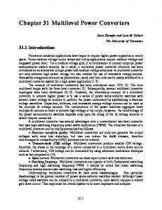
Fig. 1. Multicell topology based on single-phase diode-rectifier power cells: (a) conventional arrangement, (b) standard power cell, (c) proposed arrangement with magnetically coupled power cells, and (d) power cells magnetically coupled.
III. P ROBLEM OF THE DC-L INK C APACITOR F ILTERING
To avoid the existence of interharmonics, it is necessary to filter out the current harmonics in the dc-links, which will require large dc capacitors. It is possible to obtain an expression for the design of the dc-link capacitor in the power cell considering the maximum load current as well as the minimum frequency in the output of the converter, as presented in [12]. This can be written as C=
h1 Io[max]
8πfo[min] Vch2
(1)
h1 where Io[max] is the maximum output current amplitude in the converter, fo[min] is the minimum operating frequency of the load, and Vch2 is the amplitude of the second voltage harmonic that is allowed in the dc-link capacitor.
Although the capacitor (1) is usually designed to attenuate the second voltage harmonic amplitude (Vch2 ) present on the dc side of the inverter, it should also prevent the second current harmonic (or other current harmonics) taken by the inverter from circulating throughout the rectifier stage. However, this second goal is difficult to accomplish without oversizing the dc capacitor. This issue is explained by considering Kirchhoff’s current law at the dc-link node ir = ic + ii
(2)
where ir is the output rectifier current, ic is the capacitor current, and ii represents the current required by the inverter. Clearly, if the rectifier current ir is required to be harmonics free, the capacitor current ic must contain all the inverter components. This could be expensive because it would require