FERMILAB-CONF-11-586-E
Improving Single Slope ADC and an Example Implemented in FPGA with 16.7 GHz Equivalent Counter Clock Frequency Jinyuan Wu, John Odeghe, Scott Stackley and Charles Zha
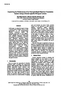
Abstract— Single slope ADC is a common building block in many ASCI or FPGA based front-end systems due to its simplicity, small silicon footprint, low noise interference and low power consumption. In single slope ADC, using a Gray code counter is a popular scheme for time digitization, in which the comparator output drives the clock (CK) port of a register to latch the bits from the Gray code counter. Unfortunately, feeding the comparator output into the CK-port causes unnecessary complexities and artificial challenges. In this case, the propagation delays of all bits from the counter to the register inputs must be matched and the counter must be a Gray code one. A simple improvement on the circuit topology, i.e., feeding the comparator output into the D-port of a register, will avoid these unnecessary challenges, eliminating the requirement of the propagation delay match of the counter bits and allowing the use of regular binary counters. This scheme not only simplifies current designs for low speeds and resolutions, but also opens possibilities for applications requiring higher speeds and resolutions. A multi-channel single slope ADC based on a lowcost FPGA device has been implemented and tested. The timing measurement bin width in this work is 60 ps, which would need a 16.7 GHz counter clock had it implemented with the conventional Gray code counter scheme. A 12-bit performance is achieved using a fully differential circuit making comparison between the input and the ramping reference, both in differential format. Index Terms— Front End Electronics, TDC, FPGA Firmware
T
I. INTRODUCTION
single slope ADC is a simple digitization scheme with low noise interference and low power consumption [1-4]. A conventional implementation scheme of the single slope ADC is shown in Fig. 1. In each channel, the input analog signal level is compared with a periodic ramping reference voltage. When the ramping voltage passes across input level, the logic level of the comparator output flips from low to high. The transition drives the clock (CK) port of a register so that the bits of a Gray code counter are stored. The stored count HE
Manuscript received November 5, 2011. This work was supported in part by Fermi Research Alliance, LLC under Contract No. DE-AC02-07CH11359 with the United States Department of Energy. J. Wu is with Fermi National Accelerator Laboratory, Batavia, IL 60510 USA (phone: 630-840-8911; fax: 630-840-2950; e-mail: jywu168@ fnal.gov). J. Odeghe is with South Carolina State University; 300 College St NE , Orangeburg, SC 29115, (e-mail:
[email protected]). S. Stackley is with Boston University, 590 Commonwealth Avenue, Boston, MA 02215, (e-mail:
[email protected]). C. Zha is with Rice University, 6100 Main, Houston, Texas 77005, (e-mail:
[email protected]).
reflects the crossing time between the ramping reference and the input level so that the analog input level is digitized.
+ CMP -
Register
+ CMP -
Register
f
Gray Code Counter
Fig. 1. A conventional implementation based on Gray Code Counter.
Unfortunately, feeding the comparator output into the CKport of the register causes unnecessary complexities and artificial challenges. In this scheme, the propagation delays of all bits from the counter to the register inputs must be matched, i.e., all bits must have the same propagation delay between the outputs of the Gray code counter and the inputs of the registers. The differences of the delay times between different bits become the differential non-linearity. Since the transition time of the comparator output has no defined phase relation with the system clock, the counter must be a Gray code one. In this document, we will first discuss a simple improvement based on the principle of timing uncertainty confinement. The spirit of timing uncertainty confinement allows improving the single slope ADC performance with not only multi-sampling, but also other TDC schemes. We will then describe implementation and test of a multi-channel single slope ADC in a low-cost FPGA device using the Wave Union TDC developed in our previous work [5-7]. The timing measurement bin width in this work is 60 ps, which would need a 16.7 GHz counter clock had it implemented with the conventional Gray code counter scheme. II. TIMING UNCERTAINTY CONFINEMENT A small improvement on the circuit topology will avoid the unnecessary challenges described above, eliminating the requirement of the propagation delay matching of the counter
bits and allowing the use of regular binary counters. The improvement is simply feeding the comparator output to the D-port of a flip-flop register as shown in Fig. 2(a), rather than feeding into the CK-port. In this case the output of the comparator is sampled with the system clock and the sampled result is used to hold the bits of the coarse time counter in the register, which reflects the digitized time. + CMP -
Hold
+ CMP -
Hold
f
Coarse Time Counter
(a) + CMP -
Hold
+ CMP -
Hold
f
Coarse Time Counter
(b) Fig. 2. Improved single slope ADC schemes: (a) with one sample per clock cycle and (b) with two samples per clock cycle.
It can be seen that the timing uncertainty is confined in the input side of the sampling flip-flop and the timing relationships in rest of the circuit are well defined by the system clock. In this case, there is no need to match the propagation delays of the bit lines between the outputs of the coarse time counter and the inputs of the registers. The only requirement on these delays is that they should be short enough to satisfy the setup time of the registers, but they are allowed to have relatively large skews and temperature variations. A curved bus is utilized in the diagram to emphasize this freedom. This scheme not only simplifies designs for low speeds and resolutions, but also opens possibilities for applications requiring higher speeds and resolutions. For example, one may use the multi-sampling method to increase digitization resolution or to increase digitization rate. In Fig. 2(b), sampling on both edges of the clock allows the users to either increase the digitization resolution from 7 bits to 8 bits or
double the digitization speed if 7-bit resolution is sufficient. Again in this case, the timing uncertainty is confined in the inputs of the two sampling flip-flops, and matching delays of the counter bit lines are not needed. Even further improvements with 4, 8, 16, 32 samples/clock are possible with increase of silicon area. See [2] as an example. It is interesting to review the topology utilized in Fig. 3 of [2], where the comparator output is fed into the D ports of the Synchronizer and the flip-flops registering the DLL outputs, so that the timing uncertainty is confined. (However, it would be even better if the output of the Synchronizer were not used as the clock input to the Memorization register recording the counter outputs. Using register output as clock of another register may not violate setup time requirement but may risk violating hold time of the second register.) Note that in both Fig. 2(a) and (b), the coarse time counters are regular binary counters, not Gray code counters, which further simplify the system design and data analysis. There is a natural fear that the system clock distributed in this scheme will generate noise to the analog portion of the ADC. We will show that the spectrum of the clock noise is far higher than the analog cut-off frequency of the input and will not degrade the ADC performance. Consider a 7-bit ADC with a counter clock frequency f as an example. The maximum sampling frequencies are (f/128) for the scheme shown in Fig. 2(a) or (f/64) for the scheme shown in Fig. 2(b). Base on sampling theorem, before analog signal is sent to ADC, there must be an anti-alias low-pass filter with Nyquist frequency less than half of the sampling frequency. Even in a simplest RC filter with 20 dB/decade frequency respond, more than a factor of 100 attenuation can be anticipated at frequency f. Therefore, as long as the clock noise level is less than the full voltage range at the filter input, the ADC error caused by the clock noise is smaller than an LSB. III. THE SINGLE SLOPE ADC IMPLEMENTED WITH FPGA In fact, the scheme given above can be considered as a special case of coarse time handling in TDC design and a crucial practice in TDC design is to confine the timing uncertainty. A suitably designed TDC that provide significantly finer time measurement resolution than a clock cycle can be utilized in single slope ADC with either higher sampling rate, or more digitization bits or both. Differential input ports are available in most FPGA families today which can be used as comparators in the single slope ADC. A multi-channel single slope ADC using TDC scheme built in a low-cost FPGA device is shown in Fig. 3.
4xR2
FPGA
Vc+
VIN1 +
FPGA TDC
TDC 4xR2
R
R
C
R
V REF+
C V REF-
1.5 V 1
R
VREF
Vin-/2
2 VIN2 + VIN2 -
TDC
Vin+/2
2.5
TDC
VIN1 -
Vc-
0.5 0
R1
R1
(a) (b) Fig. 3. Single slope ADC schemes implemented using FPGA: (a) singleended version and (b) fully differential version
It is possible to use single-ended topology as shown in Fig 3(a) for its simplicity and high input impedance. Clearly the concern is the input noise coupled through ground plane. It is also fairly common that the signal source is differential coming from a differential amplifier as the ADC driver and that a high ADC resolution is required. In this case, the fully differential topology given in the Fig. 3(b) is a suitable choice. In both schemes, the ramping reference voltage is derived from a pair of output pins of the FPGA which generate a square wave with 50% duty cycle. Through the symmetrical resister and capacitor network, a ramping wave form is generated. The upward and downward ramps are exponential functions and the voltage swing and the time constant can be adjusted by choosing R, C and R1 values. It should be pointed out that the output pins from the FPGA used here are not in true LVDS or other differential standard. In order to generate a stable ramping reference voltage, these pins are assigned with regular low impedance single-ended output standard such as LVCOMS. To reduce timing skew between the outputs, registers on the I/O pads are utilized. The ramping voltages for differential scheme must be buffered with amplifiers, either a differential amplifier or two single output operational amplifiers. The ramping voltage for single ended scheme can be sent directly to the differential input pins although buffering may also be utilized in practical applications. In the fully differential version of the comparing circuit, the voltages at the comparator pins VC+ and VC- are simply the means of corresponding input voltage and the reference voltage, i.e., VC+ = (VIN+ + VREF+)/2 and VC- = (VIN- + VREF)/2. To visualize the effect, the input voltages and the voltages at the comparator pins are plotted in Fig. 4.
0
32
64
96
128
160
192
224
256
t (ns)
Fig. 4. External input voltages and the voltages at the comparator pins.
Note that when the input voltages deviate from the baseline, the ramping waveforms move up or down symmetrically. The crossing times (relative to the vertical grid lines) of VC+ and VC- change accordingly. These crossing times provide information of the input voltage levels at given times. IV. TEST RESULTS Both single-ended and differential single slope ADC schemes are tested. The differential scheme is targeted to a high resolution but slow sampling rate application which is 12-bit at 2 M samples/s in our case. The single-ended scheme is configured to digitize at high rate with relatively low resolution which is 7-bit at 62.5 M sample/s. The test hardware and results are described in the following. A. The Differential Scheme A 16-channel single slope ADC prototype module is shown in Fig. 5.
Fig. 5. A 16-channel single slope ADC prototype module
Signal amplification, anti-alias low-pass filter and ADC drivers are built using differential amplifiers placed in the left section on the module. The FPGA performing the TDC functions is the 144-pin package Altera Cyclone II device [8] (EP2C8T144C6 costs $28, $1.75/channel) located in the middle of the module. The effective bin width of the FPGA Wave Union TDC is approximately 60 ps. A pulse about 15 μs wide with both polarities is generated in differential format. Differential ramping reference voltages are generated at 2 M samples/s, i.e., 500 ns ramping up and 500 ns ramping down. Both crossing time for ramping up and down are recorded and processed. Both sets of the time records are calibrated to compensate the exponential ramping function and an offset due to difference of the comparator
responses on upward and downward ramping. The oscilloscope traces of the input signals and the digitized data are shown in Fig. 6.
intended to be a quick test platform and the electrical characteristics are not as optimal as a dedicated printed circuit board. The ramping reference voltage is generated at 62.5 M sample/s, i.e., 16 ns ramping up and 16 ns ramping down. The TDC inside FPGA records crossing times and the data are readout through a USB cable to a PC. The input signals and the digitized raw data are shown in Fig. 8.
(a)
(a) Falling
Rising
5 12 4 48
(b) Fig. 6. Test results: (a) the test pulse and (b) digitized data.
3 84 ts 3 20 n u o 2 56 C C D 1 92 A 1 28 64 0
Due to limited gain of the comparator, i.e., the differential receiver in the FPGA, it is not obvious that a high precision of the ADC is achievable, which is what to be verified in our tests. Using a fully differential circuit to make comparison between the input and the ramping reference, both in differential formats, a 12-bit performance has been achieved. B. The Single-ended Scheme The hardware we used to perform the test on the singleended single slope ADC is shown in Fig. 7.
0
400
800
1200 1600 2000 2400 2 800 320 0 360 0 4000 ns
(b) Fig. 8. Test results: (a) the test pulse and (b) digitized raw data.
It can be seen that the digitized data follow the input pulses as expected. Large noise can be seen in the digitized raw data partially due to the single-ended scheme and partially due to long signal paths from the prototype board to the FPGA pins through the daughter card. The output from the FPGA TDC is a 9-bit integer but not the entire range is valid and the various noise sources in the device cause the least significant bit to be unusable. So as a coarse estimate, the ADC resolution is approximately 7 bits. Improvements can be anticipated with better hardware. Nevertheless, the input pulses are detectable and total charge can be coarsely estimated even with nonoptimal hardware. V. CONCLUSION
Fig. 7. The hardware for single-ended single slope ADC tests.
The FPGA performing the TDC function is an Altera Cyclone III device [9] (EP3C25F324C6N) located on an evaluation card. The bin width of the FPGA Wave Union TDC is approximately 40 ps. However, due to noise from switching power supply on the board, the actual TDC resolution is similar as in Cyclone II with 60 ps effective bin width. The FPGA I/O pins are connected via a daughter card to the prototype board hosting input connectors and the ramping voltage generating RC network. The hardware is
Test results of a high resolution low sampling rate and a low resolution high sampling rate single slope ADC schemes are presented in this paper. Today, TDC in FPGA has reached such a fine time resolution so that it becomes feasible to implement a “fully digital” single slope ADC with an FPGA plus a few passive components for most applications in high-energy physics and nuclear science. VI. DISCUSSION The names of two ADC schemes, “single slope/ramp ADC”
and “Wilkinson ADC” sometimes are not well distinguished in publications. The analog-to-time conversion (ATC) based ADC can be classified into two large categories, i.e., singleslope and dual-slope ones. The dual-slope ADC can also be called Wilkinson ADC, in which the analog signal is first charged into a capacitor and then discharged. The discharge time is digitized to reflect the amplitude of the input analog signal. Sometimes, the charging slope is so fast that it appears to have only one slope. But as long as the analog input is charged into a capacitor, is belongs to dual-slope category. This scheme is called Wilkinson ADC since this scheme is closest to Wilkinson’s original work [10]. In the single-slope scheme, the input analog voltage is sent to one input of a comparator and the reference ramp is sent to another input of the comparator. The input signal is not charged into a capacitor and then discharged. The Wilkinson ADC is suitable for charge measurement since the measurement result does not depend on the capacitor value. The single slope ADC scheme, on the other hand, is suitable for voltage measurements since the input analog signal is sent to the high-impedance input of the comparator and it is not manipulated as in dual-slope scheme. The references [1-4] are examples of single-slope ADC and the reference [11] is a dual-slope ADC. This classification is not a trivial name game since the two schemes do affect design simplicity (or complexity) and performance. The applications in [1-4] demand voltage measurement while the application in [11] requires charge measurement and the choice of the ADC scheme are suitable in these cases. If opposite choices are made, i.e., using Wilkinson ADC to measure voltage or using single slope ADC to measure charge, extra artificial challenges are often created. ACKNOWLEDGEMENT The authors would wish to express thanks to the Summer Internships in Science and Technology (SIST) program of Fermi National Accelerator Laboratory, the Science Undergraduate Laboratory Internship (SULI) of the Department of Energy Office of Science and Rice University. REFERENCES [1] [2] [3] [4] [5] [6] [7]
D. Yang, B. Fowler & A. Gamal, “A Nyquist Rate Pixel Level ADC for CMOS Image Sensors,” in IEEE 1998 Custom Integrated Circuit Conference, Page(s): 237 - 240. E. Delagnes, et. al., “A Low Power Multi-Channel Single Ramp ADC With Up to 3.2 GHz Virtual Clock,” in IEEE Transactions on Nuclear Science, 2007, Pages 1735 - 1742, vol. 54. W. Da Silva, et. al., “A 130nm CMOS Digitizer Prototype Chip for Silicon Strips Detectors Readout,” in Nuclear Science Symposium Conference Record, 2007, Page(s):1861 - 1864. J. Crooks, et. al., “A CMOS Image Sensor With In-Pixel ADC, Timestamp, and Sparse Readout,” in IEEE Sensors Journal, 2009, Pages 20 - 28, vol. 9. J. Wu & Z. Shi, “The 10-ps wave union TDC: Improving FPGA TDC resolution beyond its cell delay”, in Nuclear Science Symposium Conference Record, 2008 IEEE, 19-25 Oct. 2008 Page(s):3440 - 3446. J. Wu, “Several Key Issues on Implementing Delay Line Based TDCs Using FPGAs,” in IEEE Transactions on Nuclear Science, 2010, Pages 1543 - 1548, vol. 57. H. Sadrozinski & J. Wu, “Applications of Field-Programmable Gate Arrays in Scientific Research”, Taylor & Francis, December 2010.
[8]
Altera Corporation, “Cyclone II Device Handbook”, (2007) available via: {http://www.altera.com/} [9] Altera Corporation, “Cyclone III Device Handbook”, (2010) available via: {http://www.altera.com/} [10] D. Wilkinson, “Blood, Birds, and the Old Road,” in Annu. Rev. Nucl. Part. Sci. 1995, Pages 1-39, vol. 45. [11] S. Tedja, et. al., “A CMOS Low-Noise and Low-Power Charge Sampling Integrated Circuit for Capacitive Detector/Sensor Interface,” in IEEE Journal of Solid-State Circuits, 1995, Pages 110 - 119, vol. 30.