Improving Symbolic Execution for Statechart Formalisms Daniel Balasubramanian
˘ areanu ˘ Corina Pas
Michael W. Whalen
Vanderbilt University Nashville, TN
NASA Ames Research Center Mountain View, CA
University of Minnesota Minneapolis, MN
[email protected] [email protected]@cs.umn.edu Gábor Karasi Michael Lowry Vanderbilt University Nashville, TN
NASA Ames Research Center Mountain View, CA
[email protected] [email protected] ABSTRACT
semantic variants of Statecharts have been used together to model different, interacting components of a large system is the Constellation program at NASA. While the use of multiple tools is convenient for developers, component integration and analysis can be difficult due to different semantics between the tools. One form of analysis that is well-suited to Statecharts is symbolic execution [6]. Symbolic execution is a program analysis technique that systematically explores different program paths by using symbolic values rather than actual data values as inputs and computing the values of program variables as symbolic expressions in terms of the symbolic inputs. When applied to Statechart formalisms, symbolic execution can determine all feasible paths through a model up to a user-specified bound and perform test-case generation by generating sequences of inputs that drive a model through those paths. However, there are two major hurdles to using symbolic execution to analyze Statechart models. First, a suitable symbolic execution engine, which can execute a model symbolically, must be integrated with the modeling framework. Second, symbolic execution can be computationally expensive when analyzing large, complex pieces of code. In our previous work, we addressed the first problem by developing Polyglot [2], a unified framework in which interacting components modeled with different Statechart variants can be simulated and analyzed. Polyglot works by translating the structure of a model into Java code, and then combining this structure code with pluggable modules that implement the semantics of different variants of Statecharts. To perform analysis, Polyglot uses Symbolic PathFinder (SPF) [7], a symbolic execution engine built on top of Java PathFinder (JPF)’s custom virtual machine [1]. SPF generates path coverage tests up to some depth; these could be used to test a Statecharts compiler or a modelbased implementation. While this approach scales for small to medium sized examples, the performance of SPF on large models can be slow, due to the interpretation overhead of the custom virtual machine. This paper describes two contributions that improve the performance of symbolic execution for Statechart formalisms. The first is a multithreaded symbolic execution engine for Polyglot. Even though the symbolic execution of Statecharts and multithreaded symbolic execution have been described elsewhere independently ([9] and [8], resp), our new framework provides some advantages, such as the ability to handle both hierarchy and parallel states. Additionally, the design
Symbolic execution is a program analysis technique that attempts to explore all possible paths through a program by using symbolic values rather than actual data values as inputs. When applied to Statecharts, a model-based formalism for reactive systems, symbolic execution can determine all feasible paths through a model up to a specified bound and generate input sequences exercising these paths. The main drawback of this method is its computational expense. This paper describes two efforts to improve the performance of symbolic execution within our previously developed framework for Statechart analysis. One method is a multithreaded symbolic execution engine targeted directly at our framework. A second, orthogonal, method is program specialization with respect to a particular model and Statechart semantics, which uses symbolic execution to rewrite the original code into an equivalent form that has fewer instructions and is easier to analyze.
Categories and Subject Descriptors D.2.5 [Testing and Debugging]: Symbolic execution
General Terms Design, languages, verification
Keywords Symbolic execution, analysis, Statecharts, test case generation.
1.
INTRODUCTION
Since their introduction, Statecharts [5] have become one of the most widely used model-based notations for describing complex, reactive systems. There are literally dozens of variants of Statecharts, each having a similar but slightly different execution semantics [3]. One example where multiple
c 2012 Association for Computing Machinery. ACM acknowledges that
this contribution was authored or co-authored by an employee, contractor or affiliate of the United States government. As such, the United States Government retains a nonexclusive, royalty-free right to publish or reproduce this article, or to allow others to do so, for Government purposes only. MoDeVVa ’12, September 30 2012, Innsbruck, Austria Copyright 2012 ACM 978-1-4503-1801-3/12/09 ...$15.00.
47
= type = OP val = “=”
State machine model in Java Simulink/Stateflow
(1)
x
(2)
IMPORT
GENERATE
t0
Modeling / Intermediate Representation
A
{a = x + 1} B
t1
// x is an integer input // a is an internal integer
Rhapsody
Generic Execution Environment
(4) Data interface Java PathFinder / Symbolic PathFinder
of Polyglot, which decouples the semantic modules from the “structure” of a Statechart model, readily lends itself to a multithreaded implementation. The second complementary contribution is the application of program specialization to the generated Polyglot code for particular models and particular semantics. The approach is akin to partial evaluation [4] and it uses SPF to first examine the model in Polyglot and then to generate a specialized version whose semantics are equivalent to the original. The specialized code is simplified with respect to a Statechart model, resulting in fewer instructions to be executed and analyzed by SPF when further analyzing or simulating the model.
2.1
D
SymbolicNode
SymbolicNode
x type = VAR index = 1
+ type = OP val = “+” SymbolicNode
1 type = VALUE val = “1”
SymbolicNode
Initially Variables take initial values. x is symbolic, a is 0.
1. Step one The condition tree is walked and the value of a is updated. Variable values are retrieved using the index.
Symbolic values a0 = 0 x0 = symbolic
Symbolic values a1 = x1 + 1 x1 = symbolic
variables. As a result, the outputs computed by a program are expressed as a function of the symbolic inputs. The state of a symbolically executed program includes the (symbolic) values of program variables, a path condition (PC), and a program counter. The path condition is a boolean formula over the symbolic inputs, collecting the conditions on the inputs along the explored paths. The paths followed during the symbolic execution of a program are typically characterized by a symbolic execution tree.
3.
CUSTOM SYMBOLIC EXECUTION FOR POLYGLOT
This section describes the design and implementation of a multithreaded symbolic execution engine for Polyglot. As mentioned previously, using Symbolic PathFinder (SPF) to analyze Statechart models in the Polyglot framework can be computationally expensive. In general, symbolic execution may be expensive due to the large number of paths to explore. Furthermore SPF performs symbolic execution by implementing a non-standard interpreter of Java bytecodes inside JPF’s custom virtual machine. The use of the custom virtual machine alone incurs significant interpretation overhead. In addition, the execution of each transition step in the model involves invoking and executing several Java datastructures and methods that provide the implementation in Polyglot; in other words, SPF is symbolically executing the execution engine that executes the model, and this has a much larger state space than the model itself. In order to remove the overhead of SPF, we designed and implemented a custom symbolic execution engine targeted directly at models in the Polyglot framework. For our initial effort, we refactored the Stateflow semantic module from a concrete execution engine into a symbolic execution engine. Additionally, we designed this engine with multithreading in mind, so that analysis can be distributed across multiple cores. The rest of this section describes the design and implementation, using a small example to explain the involved concepts and algorithms. Even though this presentation is done in the context of Stateflow semantics, we believe this approach generalizes, and that our methods can be used as a “recipe” for constructing symbolic execution engines for other Statechart like modeling languages as well.
BACKGROUND Polyglot
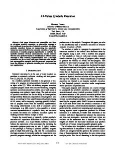
Figure 1 gives an overview of the Polyglot framework[2]. Components can be defined inside the Simulink/Stateflow or Rational Rhapsody environments (top-left corner of Figure 1) and automatically imported into an intermediate representation. From the intermediate representation, Java code representing only the structure of the model, not the semantics, is generated (top-right corner of Figure 1). In this way, the semantics of a paticular Statechart variant are decoupled from the structure of the model, allowing, for instance, different models to be simulated and executed with multiple semantics. To execute a model, the generated structure code is combined with a semantic module, currently for either Stateflow, UML or Rhapsody semantics. To perform analysis, the semantic modules expose a generic data interface that SPF uses to interact with and control the symbolic execution of a model. One important feature of the Polyglot design is the decoupling of the structure of a Stateflow model from its semantics. Figure 1 shows that the structure of a model is turned into Java code and combined with the semantic modules to provide an execution. With respect to the “state” of a model, the semantic modules hold only a list of currently active states. This design allows the semantic modules to act as interpreters of the generated structure code: a module can inspect and set the variable values for a model while storing the list of active states internally. Section 3.3 describes how this eases our multithreaded implementation.
2.2
[a < 0]
a type = VAR index = 0
SymbolicTree for t1’s condition action
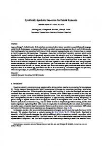
Figure 2: A condition action tree and the update to symbolic variables.
Figure 1: Overview of the Polyglot framework.
2.
t3
[a > 0]
SymbolicNode
0.
Rhapsody Stateflow UML (3) Pluggable Semantics
t2
C
3.1
Symbolic execution
Running example
The example Statechart model that will be used to illustrate the concepts throughout this section is shown in the top left-hand corner of Figure 2. This model has four states (A, B, C and D), four transitions (t0, t1, t2 and t3 ) and two
Symbolic execution [6] is program analysis technique that uses symbolic values instead of actual data as inputs and uses symbolic expressions to represent the values of program
48
integer data variables: an input variable x and an internal variable a. Transition t1 is labeled with a condition action, meaning that when transition t1 is taken, a is assigned the value x + 1. Transition t2 and t3 each have a guard, which is a condition that must be true for the transition to be valid. The guard on t2 states that the value of the variable a must be greater than zero, while the guard on t3 states that the value of a must be less than zero. Execution of this model with Stateflow semantics works in the following way. Initially, assume the model is in state A and the value of a is zero. At the beginning of every step of execution, the value of the input variable x is read from the environment. Next, transition t1 is tested, and because it has no guard, t1 is taken, its condition action performed, and the current state becomes state B. The condition action of t1 assigns to variable a the current value of the input variable, x, plus one. At the next step of execution, first the guard on transition t2 is tested, and if true, t2 is taken and the current state is state C. Otherwise, the guard on transition t3 is tested, and if true, t3 is taken and the current state is state D. If the guard on neither t2 nor t3 evaluates to true, the current state remains state B.
3.2
x + 1 to the internal variable a. In order to perform this assignment, we first parse a = x + 1, retrieving the current symbolic value of x from the list of symbolic values. Next, we update the symbolic value of the variable a based on the assignment. The reasons for the actions above is that, in general, assignment expressions, such as the one found on the condition action of transition t1, can be arbitrarily complex, and the values of all the variables used in the expression must be retrievable from the array of symbolic values contained by the current symbolic snapshot. However, in order to retrieve the current value of a symbolic variable, information is needed about where the variable is stored, such as an index into the array of symbolic values held by a SymbolicSnapshot. The top-right hand portion of Figure 2 shows the example model augmented with a tree structure holding the expression in the condition action on t1. Each node in the tree in Figure 2 is an instance of the SymbolicNode data structure (Listing 1). In addition to a member variable giving its type, each SymbolicNode has an index, which is an integer index into the array of symbolic values held by the SymbolicSnapshot. When the symbolic execution engine walks the tree corresponding to an expression (in this case, a = x + 1 ), the index held by a SymbolicNode will be used to retrieve the current value of the variable from the array of SymbolicValue variables held in a SymbolicSnapshot. This allows the generated code for specific Statechart models to interact with the data held by the symbolic execution engine. The bottom part of Figure 2 describes how the values of the symbolic variables are assigned as the model is executed. Generalizing from this example, a SymbolicValue data structure is shown in Listing 1.
Symbolically executing a model
At a high level, symbolic execution of the model in Figure 2 means that instead of reading a specific, concrete value from the environment for the input variable x at each step of execution, a symbolic value is used instead. Whenever x is used in actions, such as transition t1, or in guards, such as transitions t2 and t3, the symbolic value is used. When a branching condition is reached, such as whether the guard on a transition is true or false, both paths are explored by forking execution and attaching a path constraint to each separate path. Along any given path of a symbolically executed program, the path constraint states what conditions must be satisfied in order for a path to be satisfiable. Generalizing this high-level description and the sample execution, a path of symbolic execution of a Statechart model needs three pieces of information. A data structure holding this information (named SymbolicSnapshot) is shown at the top of Listing 1 and explained below. The first item in the SymbolicSnapshot data structure, a list of active states, is also used in concrete execution. This simply tells which states in the model are active in an execution path. This list depends on symbolic values only in that the path constraints and assignments to symbolic variables must be satisfiable for this list of states (and path) to be valid. The second item in the SymbolicSnapshot data structure is an array of symbolic values of the variables in a model. To describe a data structure for holding the variable values, consider again the model in Figure 2. We assume that initially, the model is in state A and that the value of variable a is 0. With ordinary, concrete execution, at the beginning of a step of execution, the value of the input variable x is read from the environment. However, because the model is being symbolically executed, at the beginning of each step, a symbolic value is assigned to x (this symbolic value can be denoted with a special symbol in the implementation). After a symbolic value has been assigned to the input variable x for the current step, transition t1 is tested. Because t1 has no guard condition, its condition action is performed. The condition action of t1 assigns the value of the expression
1 2 3 4 5 6 7 8 9 10 11 12 13 14 15 16 17 18 19 20 21 22 23 24
class SymbolicSnapshot { L i s t s t a t e s ; // t h e c u r r e n t s t a t e s SymbolicValue [ ] v a l u e s ; SymbolicConstraint constraint ; } c l a s s SymbolicNode { int index ; // i n d e x i n t o SymbolicValue [ ] Type t y p e ; enum Type { VAR, OPERATOR, VALUE } S t r i n g v a l ; // f o r VALUE t y p e s } c l as s SymbolicValue { // name , d a t a t y p e and v a l u e o f v a r i a b l e S t r i n g name , dataType , v a l u e ; S y m b o l i c V a l u e p r e v ; // p r e v i o u s v a l u e i n t seqNum ; // t h e s e q u e n c e number } class SymbolicConstraint { S t r i n g c o n s t r a i n t ; // v a l u e o f c o n s t r a i n t S y m b o l i c C o n s t r a i n t p r e v ; // p r e v i o u s v a l }
Listing 1: Data structures for symbolic execution. The third and final item in the SymbolicSnapshot data structure holds constraint information. The core of symbolic execution is what happens during branching conditions: execution is forked and an attempt is made to explore both paths. Recall that an instance of the SymbolicSnapshot contains all necessary information about a path of execution. When a branching condition is encountered, both paths can be explored in the following way. First, two copies of the current SymbolicSnapshot are made. Next, a path constraint
49
State sequence: A -> B -> C Path constraint a1 > 0 Symbolic variable constraints a1 = x0 + 1 && a0 = 0 && x0 = symbolic && x1 = symbolic
State sequence: A -> B -> D Path constraint !(a1 > 0) && a1 < 0 Symbolic variable constraints a1 = x0 + 1 && a0 = 0 && x0 = symbolic && x1 = symbolic
State sequence: A -> B -> B Path constraint !(a1 > 0) && !(a1 < 0) Symbolic variable constraints a1 = x0 + 1 && a0 = 0 && x0 = symbolic && x1 = symbolic
1. The initial snapshots are fed into the execution engine.
Symbolic snapshots
2. A step of execution generates new symbolic snapshots.
Symbolic execution engine 5. The satisfiable snapshots are fed back into the execution engine.
Figure 3: The path constraints for the three possible symbolic execution paths after two steps of execution.
New symbolic snapshots
3. The path constraints and variable constraints are given to a constraint solver.
Constraint solver
Satisfiable symbolic snapshots
4. Snapshots with unsatisfiable constraints are removed.
Figure 4: The overall architecture of the custom symbolic execution engine.
asserting that the branch condition is true is appended to one of the SymbolicSnapshots, and execution proceeds along the “then” branch with the assumption that the branching condition is true using that SymbolicSnapshot. To the other copy of the SymbolicSnapshot, a path constraint asserting that the branch condition is false is appended, and execution proceeds along the “else” branch with the assumption that the branching condition is false using this SymbolicSnapshot. A path constraint contains the constraints that must be satisfiable in order for a path to be valid. After execution is forked and path constraints are appended, the constraints can be given to an off-the-shelf constraint solver and checked for satisfiability. If the constraints of a path are satisfiable, symbolic execution can proceed along that path. Furthermore, valid assignments to the input variables can be used as test-inputs that are guaranteed to drive the model through the execution path represented by a SymbolicSnapshot. If the path constraints of a SymbolicSnapshot are not satisfiable, execution along that path stops. One of the reasons SPF has interpretive overhead when analyzing models in Polyglot is that from SPF’s perspective, the Statechart model code is treated like regular Java code. This means that SPF attempts to explore both branches of every conditional statement in the semantic module code. However, there are many conditional statements found in the semantic modules that provide the implementation but are irrelevant with respect to the branching conditions of a Statechart. For Stateflow models, the branching points of interest are on the guard conditions of transitions. The custom symbolic execution engine explores both paths of only these branching points, thus avoiding the overhead of SPF. Path constraints can be represented in various ways. The SymbolicConstraint data structure at the bottom of Listing 1 implements path constraints as a linked list of strings. When a new constraint is appended to a SymbolicSnapshot, it is linked to the previous constraints held by the SymbolicSnapshot. The simplicity of this approach facilitates multithreading (Section 3.3). However, a more complex representation, such as a tree, can also be used, especially if the constraints are preprocessed before they are given to a constraint solver. Figure 3 shows the generated path constraints for each of the three possible symbolic execution paths that result from two steps of execution of the model in Figure 2. If in this example the transitions with guard conditions also had condition actions, those actions would be applied to the symbolic values contained by the SymbolicSnapshot as the transitions are taken.
3.3
Architecture and multithreading
Even though the custom symbolic execution engine alone significantly reduces the overhead imposed by SPF, multithreading can be used to scale symbolic execution even more. There has been work on multithreaded and distributed symbolic execution (see Section 6), but we are not aware of any such work that focuses on multithreaded symbolic execution specifically for Statechart analysis. The overall architecture of our singlethreaded approach is shown in Figure 4, which is labeled with annotations that describe the sequence of execution. The first step in the figure gives the initial symbolic snapshots to the symbolic execution engine. Next, the symbolic execution engine performs a step of execution, generating new symbolic snapshots. The newly generated symbolic snapshots may contain unsatisfiable constraints, so in order to discard the infeasible paths, the constraints for each symbolic snapshot are given to a constraint solver. Snapshots with unsatisfiable constraints are discarded, while the remainder of the snapshots are fed back to the symbolic execution engine and the process repeats to a user-specified depth. Multithreading is implemented in our approach in the following way. After the unsatisfiable symbolic snapshots are discarded (Step 4 in Figure 4), the remaining symbolic snapshots are divided and distributed across multiple instances of the symbolic execution engine that run in separate threads. This approach is possible because the snapshots share no writeable state information: the data structures for path constraints and symbolic values use linked lists that never modify previous elements. Section 5 gives benchmarks with the multithreaded approach.
4.
SYMBOLIC EXECUTION FOR PROGRAM SPECIALIZATION
The goal of program specialization is to reduce the interpretation overhead in Polyglot by specializing the code of the Polyglot interpreter with respect to a particular Statechart model and a particular Statechart semantics. We propose to use symbolic execution to perform the program specialization. Recall that symbolic execution uses symbolic values instead of concrete program inputs. The technique maintains a path condition for each path explored and it further computes the outputs of the program as a function of the symbolic inputs for each path. Our approach is to symbolically execute the Polyglot step() method for a particular formalism (e.g., Stateflow) for each state (and each event) in the model. Conceptually, the step() method takes as input a set of states and an event and then
50
A
B D
[y < 0]
[x < 0] C F
E
[y > 0]
[x > 0]
[y < 0]
G
[y > 0]
Figure 5: Example Statechart. Variables x and y are integer inputs. advances the Statechart to the next set of states as encoded in the Statechart. The result of symbolic execution applied to step() for one state is a set of path conditions together with the computed next states in the model and the effects on the global variables, expressed as functions over the symbolic inputs. We then aggregate the results for all the paths and all the states in the model, resulting in a specialized code for the step() method that has fewer instructions than the original code. As an example, consider the Stateflow model in Figure 5. The result of symbolically executing the step() method for state G and the empty event is shown in Listing 2 (there are no effects on the global variables in this simple example). 1 2 3 4 5 6 7 8 9
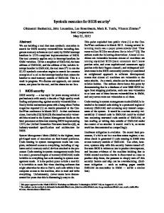
initial
Figure 6: Execution time using the different approaches. execution trees. We detect this at specialization (SPF runs out of resources) and simply fall back on the original code. Similarly for parallel states, there is no specialization performed. We remark that the result of specializing the step method for one state may result in more than one next states (hence the use of the ArrayList data structure in Listing 3); this is due to the usual semantics of hierarchical state machines. We have found experimentally that specialization can achieve up to 3 times improvement in analysis time and 10 times fewer instructions to be executed. We note that the cost of specialization is small (few seconds) and is linear in the number of states and transitions, the reason being that our analysis is modular, i.e. we first perform specialization for each state in the model and then we aggregate the results. We note that our program specialization performs a more ”aggressive” optimization than typical partial evaluation (see discussion in related work). Partial evaluation could be useful when we fall back on the original code, e.g. infinite loops.
state : G
next s t a t e s : D PC : x > 0 e f f e c t s : −− next s t a t e s : F PC : ! ( x > 0 ) && y > 0 e f f e c t s : −−
Listing 2: Results of symbolic execution for state G1. The result of symbolically executing the step() method for state F is similar (we omit the listing due to space constraints). The results of the individual specializations for each state are then aggregated resulting in the specialized step method shown in Listing 3. 1 2 3 4 5 6 7 8 9 10 11 12 13 14 15 16 17 18 19
public A r r a y L i s t s p e c i a l i z e d s t e p ( S t a t e state ) { S t a t e G, D, F , E ; L i s t s l i f ( s t a t e==G) { i f ( x > 0) s l . add (D) ; i f ( y > 0 && s l . add (F) ; s l . add ( s t a t e ) ; } i f ( s t a t e==F) { i f ( x > 0) s l . add (D) ; i f ( y < 0 && s l . add (G) ; s l . add ( s t a t e ) ; } ...
= new L i s t () ;
5.
EVALUATION
We have applied the presented techniques to the analysis of several examples that exercise different features of Statecharts, such as hierarchy, parallel states and infinite loops (i.e., loops that result in an infinite execution when executed symbolically). We report here on one particular model that contains both hierarchy and parallel states: a Statechart model containing three identical copies of the model in Figure 5, each running in parallel. For any particular step of execution, there are exactly three possible execution paths; thus, increasing the exploration depth by one increases the number of execution paths by a factor of three. We analyzed this model to different depths using (1) the original version of Polyglot with SPF, (2) Polyglot using the specialized code with SPF and (3) the custom symbolic execution engine with different numbers of threads. The experiments were performed on a 2.67GHz four core machine with 4GB RAM running 32-bit Windows 7 Enterprise. Our results are shown in Figure 6. As the graph shows, both the custom symbolic execution engine and SPF applied to specialized code achieve significant time savings as compared to SPF running with the original Polyglot code.
return s l ; x