Improving the Data Rate in Wireless Mesh Networks Using Orthogonal Frequency Code Division (OFCD) 1
Jaiminkumar Gorasia, 1Syed S. Rizvi, and 2Aasia Riasat
1
Computer Science and Engineering Department, University of Bridgeport, Bridgeport, CT-06604 2 Department of Computer Science, Institute of Business Management, Karachi, Pakistan 1 2 {jgorasia, srizvi }@bridgeport.edu,
[email protected]
Abstract-: In the present scenario, improvement in the data rate, scalability and throughput are some of the most time consuming issues in Wireless Mesh Networks (WMN). This paper discusses one of our proposed methods, i.e., improving data rate in Wireless Mesh Networks by redefining the mesh transceiver with the help of OFDM and CDMA called OFCD. The details are set down by dividing the transceiver into transmitter and receiver which incorporates OFDM and CDMA techniques. Keywords - WMN, mesh topology, mesh routers, mesh clients, multihop, scalability and different layers of TCP/IP, OFDM, CDMA
I.
INTRODUCTION
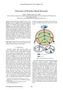
For more connectivity, mesh routers are equipped to provide connectivity between different networking technologies such as Wi-Fi, IEEE 802.11, mobile technology and wired Ethernet. In WMN, each client with same radio technology communicates via Ethernet links, for different clients communications are first made with their base station which has Ethernet connections to the mesh routers. Sometimes client nodes actually form network to perform routing and this kind of infrastructure is called client wireless mesh networks. Mesh clients can perform mesh functions with other mesh clients as well as accessing the network through routers yielding hybrid wireless mesh networks. WMN’s operation is similar to the way that packets are routed over the wired Ethernet i.e. data hops from one device to another until it reaches its destination. This is possible only when each node shares its dynamic routing algorithm with every single node to which it is connected. The routing algorithm implemented in each node takes the fastest route to its destination. As it is mentioned before, WMN is the most recent network technology it attracts researchers to do some more development and improvement in it. As the part of
it this paper is focused on the improvement of the scalability and data rate [15].There are some more research doing on better routing [13] [14]. There are only adaptive radios in mesh networks, a device in a mesh network will only connect with other devices if they are in a set range. If natural load balancing system has more devices in a network it will offer more bandwidth. Since in WMN’s there are no central servers each node (client) transmits data to as far as the next node. As a result of each node behaving like a repeater it forms an externally big network analogous to the internet. Now in today’s scenario, hybrid WMN’s have taken place of basic WMN’s. The basic advantage of Hybrid WMN is that in the Hybrid MWN network can be accessible either through mesh routers or through mesh clients. It supports all different kinds of network technologies like wired Ethernet, mobile communication, Wi-Fi, Wi-MAX, IEEE 802.11 etc. The access points form a wireless backbone, providing connectivity in places otherwise it is difficult to access through traditional wired infrastructure. The wireless communication between the access points can use different technologies such as IEEE 802.11a/b/g or IEEE 802.16 and different hardware (directional or Omnidirectional antennas).The use of multi channels in wireless network leads to throughput and reduced delay. One class of such protocols divides the available channels in two classes, control and data channels. Control channels are used to exchange network control information, while data channels are used for data transfer [3] [4].The use of multi transceiver allows a node to scan all available channels concurrently, hence solves many complex problems. II.
RELATED WORK
As it is mentioned before, this paper is focused on the improvement of scalability and throughput by some
T. Sobh et al. (eds.), Novel Algorithms and Techniques in Telecommunications and Networking, DOI 10.1007/978-90-481-3662-9_49, © Springer Science+Business Media B.V. 2010
288
GORASIA ET AL.
modification of the mesh antenna. To redesign the mesh antenna, the combined technology of OFDM (Orthogonal Frequency Division Multiplexing) and CDMA (Code Division Multiple Access) is used. OFDM is a multi carrier modulation in which multiple user symbol are transmitted simultaneously using different sub carrier [5]. Sub carriers used in OFDM have overlapping spectrum but their waveforms are orthogonal [6]. With the help of cyclic prefix longer time duration symbols are transmitted and these transmitted bits have a length longer than the length of impulse response of the channel [7]. By this way Inter Symbol Interference (ISI) is avoided which plays critical role in multipath delay spread. When the channel impulse response gets changed during an OFDM block, orthogonality of the sub channel is lost [7]. But still OFDM is much efficient for restricted wireless communication. CDMA is a spread spectrum technique which uses no frequency channels or time slots. In CDMA, pseudo random noise (PN) code which is usually of large bandwidth is multiplied with a narrow band message. In CDMA all users use same frequency band and they are free to transmit simultaneously [9]. Using OFDM and CDMA symbols are transmitted on many carriers. With OFDM technique frequency selectivity in multipath fading channel is resolved [8]. The MC-CDMA i.e. Multi Carrier CDMA is a combination of OFDM and CDMA. It uses WALSH code (it is an orthogonal spreading code sequence) in frequency domain [9]. By this frequency, diversity is achieved. The WALSH code differentiates different users and can handle number of different users, even providing good BER (Bit Error Rate). Different spread input symbols are fed to the sub carriers, when OFDM and CDMA are combined [10]. In MC-CDMA, all data symbols are not transmitted on each sub carriers. But they are transmitted on some channels. Those few channels on which data symbols are transmitted are chosen after channel assignment. Thus a problem of flat fading is resolved as only some of the bits are lost. Each sub carrier is used by different users and these users are differentiated by WALSH code. Spreading technique is used in time domain. In MC-CDMA, with receiver using FFT and variable gain diversity combiner, signal can be easily recovered. Hence transmitting and receiving a signal can be easily solved [10]. III.
PROPOSED TRANSMITTER AND RECEIVER MODEL
All system variables, along with their definition, are listed in Table I. Before we present the proposed models
Tf
TABLE. I NOTATION USED IN ANALYSIS Related Quantities Number of channels Number of nodes in unit area Frame length
Sa
Number of contention slots
Notation N N
Sd
Number of data slots
Ta(interval length) Td(length of data interval)
Contention duration Data duration
for transmitter and receiver, it is worth mentioning some of our key assumptions: • There are n available channels, each has equal bandwidth. • The access points can receive data on multiple channels simultaneously; this is a reasonable assumption since the access points can be more specialized higher end device compared to a simpler client that it serves. • The channels are orthogonal and code division multiple access (CDMA) scheme is used, i.e. transmission on a channel do not interfere with transmission on any other channels. Here a channel may represent a code or a frequency band (OFDM-CDMA modulation technique). • Each network node including the base station is equipped with multi radio, multi transceiver which is capable of performing in full duplex mode. Hence each node can either transmit or receive a signal on channel at any point of time. The nodes can however switch to different channels dynamically. • The network is synchronized [11]. A. Static And Mobile Observer For multi hop mesh network, we consider the hybrid architecture as it is the most widely deployed architecture. This architecture is characterized by the fact that mesh clients do not need direct connection to a mesh route, but can connect multi hop over mesh clients to a route. The advantages are improved connectivity and coverage. And the disadvantages are that mesh clients need more resources because they also need to have routing capability. Let’s assume there are N sensor nodes distributed over an area A. Sensors are assumed to be independently and uniformly scattered over a region of interest [12]. n - Nodes are assumed to be distributed independently and uniformly over an area of Πr2. Each
IMPROVING THE DATA RATE IN WIRELESS MESH NETWORKS
TABLE II NOTATIONS USED IN PROPOSED TRANSMITTER AND RECEIVER MODEL. Notation Related Quantities x(k) Input from digital data source x1….xN Parallel data symbols f1….fN Carrier frequency Cb PRN codes Xn Symbol mixed with PRN codes χk Output of the mixer Yk Output of IDFT block x(t) Analog received signal Non negative weight function w(k) Xk Output of DFT X(k) Output of mixer at receivers end n(t) White additive Gaussian noise G Guard time matrix
node can communicate with every other node within the radius r where, π r 2 = ( ln n + c ( n ) ) ⁄n
The networking is connected with unit probability if and only if lim c( n) → ∞ . From this, we can choose the n →∞
transmission range. After flooding the network is organized into a tree with the observer at its route. In the first step of flooding the observer first broadcasts a wakeup signal. All sensors within direct communication range hear this signal and reply to the observer, upon this observer registers them as first level nodes in the node tree and instructs them to repeat the process of broadcasting in a time shared manner to avoid collisions. All the node encountered as a result of these new broadcasts and have not been encountered previously, are registered as second level nodes. Then the second level nodes broadcasts and process repeat until all nodes have been registered. Whenever a node broadcasts wakeup signal, it also attaches its unique address and chain of nodes which leads to it, from the observer. Nodes that are wakened up by broadcast are designated as children of broadcasting node. These children obtain the chain of nodes leading from observer to them by concatenating the last link with the chain, leading to there parent. A node obtains a route to observer by reversing this chain. The same reasoning suggests that a fewest-hop route should be optimal even in a mobile observer network. But since the observer does not stay at a fixed position, the fewest-hop route is time variant in nature, and so is the number of hops. Quite obviously, the best solution is to choose the route which consists of the fewest hops at any time. In other words, if S = Ns1, Ns2, Ns3, ... is the set of all the nodes that come within direct communication range of the observer at any time, then the fewest-hop route to the observer is the shortest of the fewest-hop routes to any of the nodes in S joined with the link between the corresponding node in S and the observer. Finding the shortest route in practice involves a procedure very similar to the flooding described in section 4.1.1, but with one difference. The 1st level nodes (those belonging to the set S just described) are discovered by moving the observer on its path while transmitting a wake-up signal to all nodes that are within range. These nodes are registered as 1st level nodes. The remaining process of flooding proceeds exactly as described in section 4.1.1. At the end of it, each node in the network knows its route to one of the nodes in S that communicate directly with the observer.
289
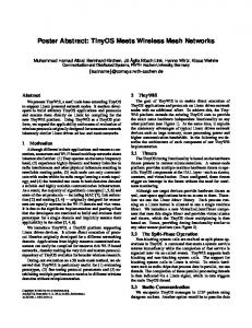
B. OFCD System Model This is a hybrid combination of OFDM and CDMA spread spectrum modulation technique. All system variables, along with their definition, are listed in Table II. Transmitter Model: As shown in Fig. 1, x(k) is the discrete digital data which a transmitter will receive from digital data source where k represents discrete time. The serial to parallel converter will convert x(k) into n number of parallel data symbols with a symbol rate of 1/T. The parallel symbols are x1(k) to xn(k). QPSK block is used which will have the carrier frequency f1 to fn as its other inputs. The QPSK block will split the input bit stream into in-phase and quadrature phase components. The quadrature components and the in-phase components will be modulated with f1 to fn carrier frequencies. The output of QPSK block would be xn ( k ) + f n , which is then supplied to the mixer. At mixer, PRN code Cb will mix with the incoming signal xn ( k ) + f n . So, the output is
X n = [ xn (k ) + f n ].Cb The Inverse Discrete Fourier Transform (IDFT) would be used for modulation and it is described as N −1
Yk = ∑ X n .e
−
2π .i kn N
n= 0
where k= 0,…, N-1. The last symbol coming out of IDFT block is taken and added on the beginning of source code block to provide guard time which in fact will provide
GORASIA ET AL.
290
Fig. 1. Proposed Transmitter Model
orthogonality (Analogous of OFDM). If the last symbol coming out of IDFT block is Xn. Then, b
< χ k , Yk >= ∫ χ k .Yk .w(k )dk
where n(t) is the noise which gets added during the transmission. The signal has been passed through the guard time removal block to remove the guard time G.
a
Where w(k) is the non negative weight function and χk and Yk would be orthogonal if, b
∫ χ k .Yk .w(k )dk = 0 a
G = (0 Nxl 1NxN 0 NxN ) where G is a matrix of 0’s and 1’s. Receiver will perform Discrete Fourier Transform (DFT) to demodulate the signal. DFT can be represented as
As the input bit stream can be of infinite length, so for infinite integral
N −1
X k = ∑ xn .e
∞
∫χ
k
.Yk .w(k )dk = X k
2
= Xn
2
−
2π .i kn N
n=0
−∞
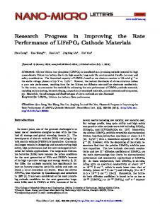
After digital to analog conversion, discrete digital signal would be converted into analog signal and then would be transmitted over the medium. Receiver Model: In Fig. 2, x(t) is the received signal which can be shown as: x (t ) = F −1[ X k ] + n (t )
where k= 0,…,N-1. Xk is then fed to the mixer which will mix it with the PRN code Cb which is deterministic to the receiver. As we are deploying the CDMA’s feature, the receiver should know the seeds of the PRN codes which were used at the transmitter. The output of mixer is represented by X(k) and can be represented as
Fig. 2. Proposed Receiver Model
IMPROVING THE DATA RATE IN WIRELESS MESH NETWORKS
X (k ) = Cb X k The Direct Sequence Spread Spectrum technique i.e. DSCDMA is used to detect X(k). DS-CDMA will simply perform the XOR operation between the PRN codes and the signal coming out of the mixer X(k). The unique chip sequence is used by DS-CDMA depends on the number of seeds used by the transmitter. Band Pass Filter(BPF) will pass only a certain range of frequency by considering the maximum and minimum frequency components of the carrier frequency. If fh is the highest frequency component and f1 is the smallest frequency component then fBPF = fh – f1 and those detected signals will be passed which lie in the frequency range of fh-f1. With the parallel to serial converter original transmitted signal x(k) will be recovered.
[8] [9]
[10] [11]
[12] [13]
[14] [15]
291
Transmission Schemes” Proceedings of 1st International OFDMWorkshop Hamburg, 21-22 September 1999. J. Proakis, “Digital Communications.New York: McGraw Hill”, 3rd ed., 1995. N. Yee, J.P.M.G. Linnartz, “Multi-carrier CDMA in an Indoor Wireless Radio Channel”, UCB/ERL, 1994. U.C. Berkeley, UCB/ERL M94/6, Electronics Research Lab. R. Van Nee, R. Prasad, “OFDM for Wireless Multimedia Communication”, Boston London: Artech House Publishers, 2000. Synchronization scheme reference IEEE working group “A Wireless LAN MAC and physical layer (PHY) Specification”, Zhou D. and Lai T.H., A compatible and scalable clock synchronization protocol ICCP 2005. P. Gupta and P. R. Kumar, Wireless Networking, 1998-99. T. Keller, L. Hanzo, “Adaptive Multicarrier Modulation: A Convencient Framework for Time-Frequency Processing in Wireless Communication,” IEEE, vol. 48, May 2000. “Wireless Communications: Principles and Practice” 2nd edition, Theodore S. Rappaport, 2002. Yi Li Lili Qiu Yin Zhang Ratul Mahajan “Effects of Interference on Wireless Mesh Networks: Pathologies and a Preliminary Solution”
Authors Biographies
IV. CONCLUSION In this paper, we have studied a multi radio multi channel Wireless Mesh Network (WMN) using OFCD which amalgamates the advantages of OFDM and CDMA. A transmitter and a receiver model are described with the help of useful mathematical expressions. This is a simple and a realistic technique and has good performance properties. In very noisy multipath channel the proposed hybrid scheme is expected to work efficiently and will give good Bit Error Rate (BER) value.We have also highlighted the potential of multi-radio wireless mesh networks, along with primary technical challenges that must be addressed for widespread deployment of such networks. Wireless mesh networks present a promising solution by extending network coverage based on mixture of above wireless technologies through multi-hop communications. REFERENCES [1] [2]
[3] [4]
[5] [6]
[7]
F. Akyildiz, X. Wang,and W. Wang,” Wireless mesh networks: a survey”, Computer Networks (2005). P. Kyasanyur and N. Vaidya “Routing and interface assignment in multi channel multi interface wireless networks” Proc. Of IEEE WCNC 2005. S.L. Wu and C.Y. Lin, “A New Multi Channel MAC Protocol” ISPAN. D.N.C. Tse and M. Grossglauser, “Mobility Increases the Capacity of Ad Hoc Networks” IEEE/ACM Trans. Net, vol. 10, no.4, Aug 2002. O. Edfors, M. Sandell, J.-J. De Beek, D. LandstrÄom, F. SjÄoberg, “An Introduction to Orthogonal Frequency-Division Multiplexing”. E. Lawrey, “The Suitability of OFDM as a Modulation Technique for Wireless Telecommunications, with a CDMA Comparison,” MSc. thesis, James Cook University, Australia, October 1997. A. Engelhart, H. Gryska, C. Sgraja, W.G. Teich, J. Lindner, “The Discrete-Time Channel Matrix Model for General OFDM Packet
SYED S. RIZVI is a Ph.D. student of Computer Engineering at University of Bridgeport. He received a B.S. in Computer Engineering from Sir Syed University of Engineering and Technology and an M.S. in Computer Engineering from Old Dominion University in 2001 and 2005 respectively. In the past, he has done research on bioinformatics projects where he investigated the use of Linux based cluster search engines for finding the desired proteins in input and outputs sequences from multiple databases. For last one year, his research focused primarily on the modeling and simulation of wide range parallel/distributed systems and the web based training applications. Syed Rizvi is the author of 45 scholarly publications in various areas. His current research focuses on the design, implementation and comparisons of algorithms in the areas of multiuser communications, multipath signals detection, multi-access interference estimation, computational complexity and combinatorial optimization of multiuser receivers, peer-to-peer networking, and reconfigurable coprocessor and FPGA based architectures.
AASIA RIASAT is an Associate Professor of Computer Science at Collage of Business Management (CBM) since May 2006. She received an M.S.C. in Computer Science from the University of Sindh, and an M.S in Computer Science from Old Dominion University in 2005. For last one year, she is working as one of the active members of the wireless and mobile communications (WMC) lab research group of University of Bridgeport, Bridgeport CT. In WMC research
292
GORASIA ET AL.
group, she is mainly responsible for simulation design for all the research work. Aasia Riasat is the author or co-author of several scholarly publications in various areas. Her research interests include modeling and simulation, web-based visualization, virtual reality, data compression, and algorithms optimization.
JAIMINKUMAR GORASIA is a M.S. student of Electrical Engineering at University of Bridgeport. He received a B.S. in Electronics & Telecommunication Engineering from Nagpur University INDIA in 2006.In the B.S. he developed the Prepaid Electricity Billing system with the help of magnetized prepaid cards, Card sensors, A/D converters, Microcontrollers, LCD display and transformers. He researched on the signal strength improvement on MTS and BTS in mobile communication. During his Masters he researched on the improvement of the High Level Architecture structure with the use of session initiation protocol. From last six month he is working on the project based on the packet sniffing and data security in computer network using LDEP protocol.