Shape memory alloy (SMA) based actuators have a number of attributes which make them useful for robotic applications. Unfortunately their response is ...
Improving the Response of SMA Actuators. R. Andrew Russell Intelligent Robotics Research Centre, Department of Electrical & Computer Systems Engineering Monash University, Clayton, VIC 3168, AUSTRALIA
Robert B. Gorbet Department of Electrical and Computer Engineering University of Waterloo, Waterloo, Ontario, N2L 3G1, CANADA
Abstract
2. Improved cooling. In the past a number of techniques have been proposed for reducing SMA cooling time, and thus achieving faster operation. Of the "static" cooling methods, water immersion, heat sinking and forced air cooling are the most common. Experiments have been performed to compare the effect of different cooling techniques [6]. Water immersion and fixed heat sinking were shown to yield the most promising results. While these measures do provide improved speed, a large increase in power consumption results from heat lost to the cooling medium. For example, Furuya and Shimada [4] describe an underwater crab-like vehicle. Underwater operation provided a ten-fold decrease in joint cycle time. However, power consumption was increased twenty times! In other work [ 6 ] , a constant flow of distilled water cooled SMA coils used as actuators for a robotic phalange. A -3dB cutoff frequency of approximately 1.5Hz was achieved, but the authors neglected to discuss the associated power consumption. For their biped robot, Hashimoto et al. [6] embedded lmm diameter SMA wires inside the robot's metal limbs, to provide heat sinking. They indicate a power consumption of approximately 200 Watts, for a response velocity of 3cmIs.
Shape memory alloy (SMA) based actuators have a number of attributes which make them useful for robotic applications. Unfortunately their response is relatively slow being limited by the speed with which the SMA can be heated and cooled. This paper describes two novel developments of the basic SMA actuator which iqprove dynamic performance. To allow rapid heating of the shape memory alloy wire without the danger of over heating an infrared temperature sensor is introduced. Cooling is improved with the aid of a mobile heat sink. :These developments are described and preliminary results are presented.
1. Introduction Over the past five to ten years there has been increasing interest in the use of shape memory alloy to make robotic actuators [ l , 2, 3, 41. SMAs have some muscle-like properties that are useful in robotics applications. They have smooth, silent operation and compact size. However, a major disadvantage is their relatively slow operating speed. Shape memory alloys are thermally activatd. At low temperatures the crystalline structure of the alloy is in its martensite form and the material is elastic; easy to stretch or otherwise deform. As the temperature is raised the crystalline structure transforms to austenite. The austenite phase is much less elastic and a large portion of strain induced in the martensite phase can be recovered in the austenite phase. SMAs which have been stretched while cool contract towards their original shape upon being heated. This contraction can be used to produce movement in an actuator. To operate quickly the SMA material in an actuator must be both heated and cooled rapidly. In this paper heating and cooling are considered as two distinct operations which are addressed separately . Techniques for improving SMA performance have been reported [51 which involve processing to modify the characteristics of commercially available SMA material. Such modified SMA materials were not considered in this project.
I FE E Int e r m t lonal Con fererice on Robotlcs and Automutlol I 0-/803-1963 6/95 $4 00 01995 It tC
2.1 Mobile heat sink. In this paper, a novel actuator construction is proposed, using a mobile heat sink. It is expected that eventually, most of the performance improvement achieved with static heat sinks can be gained, without the increase in power consumption that heat sinking normally requires. The actuator configuration is of the two-wire differential type illustrated in Figure 1. The mid-point of a length of SMA wire is anchored to a 6mm diameter shaft. This shaft is attached to an incremental optical rotary encoder and a mobile link that provides the actuator output. The encoder generates 2000 counts/revolution, giving an angular resolution of 0.18 degrees, or less than 10pm change in length of the SMA wire. A total of 35cm of 0.3" NiTi wire is used to make two 15cm lengths of active wire. The wires have a common electrical connection at the shaft and the two "free" ends have
2299
electrical lugs crimped over a knot tied in the wire. These lugs provide an electrical connection to the ends of the SMA wire and also allow the ends to be secured to a terminal block. This terminal block is adjustable and can be positioned by means of a screw. The screw is set to give a 3% pre-strain in the SMA wire, placing it approximately in the middle of the martensite stress plateau. The major innovation in this apparatus is the friction clutch mechanism linking the output shaft to the heat sink (Figure la). Its operation is shown conceptually in Figures lb, IC and Id. Shape memory alloy wire is fastened to the actuator hub and the two ends anchored at a distance, to hold the wire in tension. The mobile heat sink is connected to the hub via a felt friction pad. Initially, both wires are at room temperature, and are the same length (Figure lb). As the top wire is heated, it contracts, causing the actuator to rotate counter-clockwise. The friction clutch drags the heat sink along with the actuator hub until the heat sink contacts the lower wire (Figure IC).As the wire is further heated, the actuator continues to rotate but the friction clutch slips, permitting the heat sink to remain in contact with the lower SMA wire. The hear sink cools the lower wire, allowing it to be more easily stretched (Figure Id). In the prototype actuator, an angular rotation of 3.5 degrees moves the heat sink from one SMA wire to the other. Heat sink
Mobile link
\
SMAwir: \
Felt washer-+i
(a) Cross section view
LEEELI
the heat sink to move away from the opposite wire. Even during repetitive motion, wires are never heated while in contact with the heat sink. As a result, power consumption will be much lower than that of an equivalent fixed heat sink. The trade-off is a slight decrease in the output torque, corresponding to the torque required to make the felt clutch slip.
3. Temperature sensing. The time it takes for an SMA wire to contract is inversely proportional to power dissipated in the wire. If the timescale is small then the effects of heat dissipation can be largely ignored. In practice measurements of contraction time have been made for currents of 1.8A and 2.4A. This represents a change in inverse power by a factor of 1 to 0.56. As a result the contraction time was reduced from 0.5 sec. to 0.3 sec a factor of 1 to 0.6. However, overheating can destroy the shape memory effect and in extreme cases lead to rupture of the wire. To prevent overheating some researchers have imposed a constant current limit [8, 91. In doing so, the wire is deprived of higher transient currents, which it would be able to tolerate when cool. These higher initial currents would be capable of producing a much faster response. Another reason for wishing to monitor the wire temperature is to prevent excessive heating which does not produce any additional stress recovery in the wire but does add to the cooling problems. Kuribayashi [9] replaces current limiting with direct measurement of the wire temperature using a copper-constantan thermocouple. When the wire is cool very high currents are applied in order to heat the wire quickly and provide rapid motion. In addition, Kuribayashi increases the cooling rate by connecting several SMA wires in parallel and using forced-air cooling. With this apparatus a maximum frequency response of 0.4Hz was achieved.
3.1 Infrared sensor.
(b) The initial position
Using thermocouples to measure wire temperature presents a number of problems: (c) Heat sink contacts bottom wire
thermocouples can only be attached to relatively large diameter SMA wires, the SMA wire is constantly flexing making it difficult to attach a thermocouple reliably, it is difficult to arrange electrical isolation between thermocouple and SMA wire, and a thermocouple attached to the wire would interfere with the operation of the mobile heat sink.
n
(d) The clutch slips
Figure 1. The mobile heat sink SMA actuator.
As soon as heating of a wire ceases, the force exerted by that wire decreases, and it begins to stretch. This causes
As an alternative sensing technique non-contact infrared temperature sensing was investigated. Pyroelectric sensors used in burglar alarm motion detectors are inexpensive, sensitive and readily available. Unfortunately they only
- 2300 -
respond to changes in infrared radiation and not its absolute value. This shortcoming was addressed by "chopping" infrared energy reaching the sensor using a vibrating vane. A spring steel vane was maintained in oscillation by energy coupled into the system by a magnet attached to the vane, a fixed electromagnet and associated electronics (Figure 2). The vane oscillates at its mechanical resonant frequency of 11Hz. Collimating tubes restrict the view of the infrared sensor to a 3mm diameter disk. After amplification and bandpass filtering the output of the sensor is an l l H z sinewave whose amplitude is proportional to temperature. Ther-mometer
does respond to the varying radiation arriving through the collimating aperture (ii) and (iii). The pyroelectric sensor responds to the average infrared radiation it receives through the collimating aperture. Therefore the sensor will give the same output for a heated wire against a background of ambient temperature as it would for even irradiation from the black body heat source where the black body temperature is the spatial average of the wire and background temperatures. 2
Heater
K
1.5
L Y
g 1 0 I4
8 t3
VI
0.5
0
Sensor
0
Electromagnet
Figure 2 Infrared temperature sensor and the black body heat source.
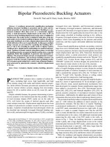
To calibrate the infrared sensor a black body heat source was constructed (Figure 2). The heat source comprises a block of aluminium heated by a 25W power resistor bolted to one face. A 0-300°C mercury in glass thermometer is located in a hole in the block to measure the heat source temperature. A second hole drilled into the block to a depth of more than six times the hole diameter acts as a black body radiator [lo]. Infrared radiation from the black body heat source is measured by the infrared sensor. Figure 3 shows a graph relating the peak-to-peak output voltage of the infrared sensor to the temperature of the black body radiator measure by the mercury in glass thermometer. The temperature readings have been scaled to indicate the temperature of a 0.3" wire crossing the centre of the 3mm diameter collimating aperture. Temperature scaling is performed as follows. From the point-of-view of the infrared sensor there are three sources of inhared radiation (Figure 4): (i) steady peripheral radiation from the sensor enclosure, (ii) radiation from the hot wire chopped at 1lHz, and (iii) radiation from the remainder of the 3mm collimating aperture also chopped at 11Hz.
100
200 300 400 Temperature ("C)
500
Figure 3 Infrared sensor output when viewing a heated 0.3" wire.
Where: tbb = temperature of a black body radiator completely filling the collimating aperture, a, = area of the collimating aperture, = temperature of the wire, a, = area of wire visible through collimating aperture, tb = temperature of the background, a, = area of that part of the collimating aperture which is at background temperature. The area of wire a, "seen" by the infrared sensor is:
where: dw = diameter of the SMA wire, d, = diameter of the collimating aperture, and the relationship between wire temperature and the infrared sensor output is: (3)
Constant peripheral radiation (i) does not register because the sensor only responds to varying inputs. The sensor
2301 -
Asymmetric open-loop results will be obtained, with the longer wire achieving greater contraction. In a closed-loop experiment, results will again be asymmetric, since the wires will be operating in different ranges of strain. To reestablish the correct zero position for the optical encoder, the SMA wires are annealed to bring the actuator to the centre of its range. To accomplish this, before each experiment the wires were subject to a linearly decaying alternating current starting at 51 Amp and decaying linearly to zero in 10 current cycles which take a total of 100 seconds. In a practical robotic application the use of absolute encoders, or some external calibration mechanism, would avoid this problem. Figure 4 Sources of heat affecting the infra-red sensor.
I IBM 486/50 compatible I
Using Equation 3, the temperature values plotted in Figure 4 were rescaled to show the sensor output that would be expected when measuring the temperature of a 0.3" diameter SMA wire. To test the validity of the use of the black body radiator to calibrate the sensor an alternative method of measuring the temperature of the SMA wire was devised. A length of 0.3" SMA wire was tensioned by a spring and its length measured at temperatures between 23°C and 100°Cusing a heated water bath. The same wire was then heated electrically to give the same deflections and its temperature measured using the infrared thermometer. In this way a second set of wire temperature versus sensor output measurements were recorded. Because of limitations of the waterbath the temperature range was much more restricted in comparison with results obtained using the black body radiator. There was good agreement between the two sets of results. A linear fit to the blackbody data has a slope of 0.00348 Volts/"C the equivalent value of slope from the water bath measurements is 0.00353 Volts/"C.
1 Infrared sensor
Figure 5. Schematic diagram of the experimental equipment.
5. Results.
4. Experimental Apparatus.
5.1 Results using the mobile heat sink.
A block diagram of the complete SMA actuator position control system is shown in Figure 5. Position data is fed from the optical encoder to a PC-486/50MHz computer, which carries out control calculations based on a target position. The control signal is current, with the sign of the error determining the sign of the current. Current drive to the SMA wire is provided by a voltage-controlled current amplifier with a transconductance of 1 AmpPolt. Two series diodes route current to the appropriate wire. Due to the incremental nature of the optical encoder, absolute position information is lost when the actuator system is powered down. Because of mechanical hysteresis in the SMA wire, it is unlikely that the actuator will come to rest in the middle position of its range of motion when power is removed. Thus when the system is reinitialised, the encoder zero may not correspond to the actual centre position of the actuator, and the wires will be at different levels of pre-strain.
Experiments were conducted to determine the effect of the mobile heat sink. The actuator was required to track a 0.16H2, It0.6" square wave input, corresponding to approximately 23 degrees of actuator rotation. Two separate trials were carried out: once with the heat sink immobilised and again with it free to move. Results are shown in Figure 6. The controller manages to eliminate some, but not all of the asymmetry in the cooled response. This asymmetry is attributed to manufacturing defects in the heat sink. Were the heat sink planer on both sides, it is expected that these problems would not occur. With the heat sink active, the response tracks the target waveform very well. If the heat sink is removed, the controller rapidly saturates the current to its preset limit of +1.8A in an effort to meet the target. This causes the overall temperature of the wire to increase, reducing its dynamic range.
2302
In an effort to quantify the increased speed made possible by the introduction of the mobile heat sink, the bandwidth of the closed loop system was measured, as it attempted to track a k0.6" square wave target. The improvement in -3dB bandwidth is very marked, having nearly quadrupled from 0.8Hz to just over 0.3Hz. The drop-off rate of the characteristic is close to 2odB/decade in both cases. Note that, unlike a linear system, the bandwidth is dependent on the input waveform. For this reason it is difficult to make meaningful comparisons with the results quoted by other authors.
(F) Because the negative wire is hot the positive wire
cannot pull the servo to its target and current is continuously limited to 1.8A. (G) The negative wire also cannot achieve its target but in this case current is controlled to limit the wire temperature to 165°C.
..........
..........
20
10
0
target
30 40 Time (sec.)
50
60
Figure 7. Closed loop controlled response of the actuator with temperature limiting applied to the SMA wire turning the output shaft in the negative direction.
1 * " " " " * * ^ 4
-20 0
10
20
30
90
100
I
Time (sec.)
Figure 6. Closed loop controlled response of the SMA actuator showing the effect of the mobile heat sink.
1
s
h
5.2 Results using temperature sensing.
Y
G o
In order to demonstrate the effects of temperature sensing tests were performed using temperature sensing without the mobile heat sink. Figure 7 shows actuator position as it attempts to track a +21 degree square wave with a period of 20 seconds. Once the target waveform has been through one full cycle the actuator cannot achieve the target because the active wire is pulling against an inactive wire which is still hot. Figure 8 shows the current applied to the actuator. Regions of interest on this graph are: (A) Current limiting in the positive direction at 1.8A. (€3) Positive current falls as target position is achieved. (C) Negative current limits at 2.4A, @) The positive wire is still hot and the negative wire has difficulty reaching the target. Current is limited back to - l A because of the wire temperature. (E) Eventually the positive wire cools sufficiently that the negative wire can pull the servo to its target and temperature limiting of the wire current ceases.
3
ii -l v)
-2
-3
1 0
.....
n
L I
.
.
,
I
10
I
,
.
,
I
20
'"',"",'"' 30 40 Time (see.)
.50
60
Figure 8. Current applied to the SMA actuator when temperature limiting is applied. Figure 9 shows the corresponding wire temperature measured by the thermal sensor. Thus higher current limits with associated faster actuation can be safely used on an SMA actuator if temperature limiting of the current is also applied.
- 2303 -
25 0
I
corresponding reduction in response time. The sensor is quite bulky and in a practical application a miniature integrated infrared sensor would be more appropriate. The development of simple, lightweight and compact actuators is an important goal in the field of robotics, where there are many potential applications. A major obstacle to the use of shape memory alloys in this effort has been their speed. This work represents a step towards the day when robots will be able to benefit from the advantages SMA actuators have to offer, without suffering the disadvantages associated with current designs.
I
Acknowledgments The authors would like to gratefully acknowledge the generous financial support of David Wang, member of the ConStruct group at the University of Waterloo. 0
10
20
30 40 Time (sec.)
50
60
References
Figure 9. SMA wire temperature measured by the infrared sensor.
.
Conclusions.
A novel mobile heat sink mechanism for a rotary SMA actuator has been described and used to construct a differential actuator, suitable for use in a robotic joint. Position control experiments were carried out. The results show a great improvement in speed of operation, as well as range of dynamic motion, over the same actuator configuration without any heat sink. Due to the nature of the mechanism, this increased performance has been achieved without the increased power consumption associated with fixed heat sinking. In its present form the prototype actuator only lunctions in one plane, where the effect of gravity on the heat sink is entirely supported by the shaft. Operation would be hindered if the mechanism were positioned such that gravity opposed, or induced, rotation of the heat sink. To overcome this problem, the heat sink must be counterbalanced in order to function in any orientation. The concept of the mobile, "intelligent" heat sink is an important one, and is not restricted to the friction clutch idea presented here. Heat sink movement could also be provided by a solenoid, or some other external mechanism. If the SMA wire temperature can be measured then larger currents can be applied to the wire producing faster movement of the actuator without the danger of over heating. The wire will also cool faster if it is not overheated. An inexpensive infrared temperature sensor has been implemented which provides non contact measurement of SMA wire temperature. This sensor has been successfully used to limit the temperature of an SMA actuator wire. With temperature limiting the maximum current was safely raised from 1.8A to 2.4A (the maximum our amplifier could provide) with a
- 2304
1. Schetky, L., 'Shape memory effect alloys for robotic
devices', Robotics Age, Vol. 6, No. 7, July 1984, pp. 13-17. 2. Nakano, Y., Fujie, M. and Hosada, Y., 'Hitachi's robot hand', Robotics Age, Vol. 6 , No. 7, July 1984, pp. 18-20. 3. Bergamasco, M., Salsedo, F. and Dario, P., 'Shape memory alloy micromotors for direct-drive actuation of dexterous artificial hands', Sensors and Actuators, Vol. 17, 1989, pp. 115-119. 4. Furuya, Y. and Shimada, H., 'Shape memory actuators for robotic applications', In Engineering Aspect of Shape Memory Alloys, (T.W. Duerig, et. al. eds.), Butterworth-Heinemann, London, 1990, pp. 338-355. 5. Hunter, I.W. et al., 'Fast reversible NiTi fibers for use in microrobotics',Proceedings of the IEEE Micro Electro Mechanical Systems Workshop, Aara, Japan, 1991, pp. 166-170. 6. Hashimoto, M., et. al., 'Application of shape memory alloy to robotic actuators', Journal of Robotic Systems, Vol. 2, No. 1, 1985, pp. 3-25. 7. Bergamasco, M., Salsedo, F. and Dario, P., 'A linear SMA motor as direct-drive robotic actuator', Proceedings of the IEEE International Conference on Robotics and Automation, 1989, pp. 618-623. 8. Madill, D.R., 'Modelling and stability of a shape memory alloy position control system', Master's Thesis, University of Waterloo, Waterloo, Canada, 1993. 9. Kuribayashi, K., 'Improvement of the response of an SMA actuator using a temperature sensor', The International Journal of Robotics Research, Vol. 10, No. 1, February 1991, pp. 13-20. 10. Anon, Omega Complete Temperature Measurement Handbook and Encyclopedia, Vol. 27, Omega Engineering Inc., 1989.