E3S Web of Conferences 36, 03006 (2018) https://doi.org/10.1051/e3sconf/20183603006 BIG 2018
Geotechnical aspects of locating the Łagiewnicka Route on the area of the “White Seas” in Kraków Jakub Zięba1*, Mirosława Bazarnik1, 1
Cracow University of Technology, Faculty of Civil Engineering, Krakow, Poland Abstract. The article presents the results of field studies and laboratory tests of the subsoil of the section of the „Łagiewnicka” route located on the area of so-called “White Seas” [1] in Kraków-Łagiewniki. The analysed samples come from the layer of anthropogenic soils being the result of the operation of the Solvay Sodium Plant in the 20th century. The results of the geotechnical and land-surveying studies served as the basis for developing a numerical model to determine the pressure on the walls of the planned tunnel and the horizontal thrust in the planned excavation. Besides, the study and test results were used to perform an analysis of the excavation’s stability and to check the impact of the sheet pile on land deformations near the John Paul II Centre in Kraków.
Keywords: Łagiewnicka Route, slope stability, MCC model
1 Introduction The construction of so-called “Łagiewnicka Route” means the construction of a road section totalling 3.5 km in length. The beginning of the route is located at the intersection of Grota Roweckiego Street with the planned „Pychowicka Route” (now Norymberska Street) whilst the end of the route is located at the intersection of Jerzego Turowicza and Wincentego Witosa Streets. The Łagiewnicka Route is part of so-called “III Krakow Ringroad” and the construction of the whole section is planned for 2018-2020. The complex geotechnical conditions along the planned section and the terrain layout characteristics of this region, require the construction of 7 tunnel facilities, including 4 twolevel intersections. Due to the planned construction of a road tunnel, located in part on the anthropogenic soils of the “White Seas”, a study and analysis were performed of the possibilities to make an excavation and the tunnel itself and of the impact of the works on the surroundings. Due to low strength parameters [2,3] of the limestone sediments in the sedimentation tanks, throughout this length, the tunnel will be located on quaternary or tertiary layers *
Corresponding author:
[email protected]
© The Authors, published by EDP Sciences. This is an open access article distributed under the terms of the Creative Commons Attribution License 4.0 (http://creativecommons.org/licenses/by/4.0/).
E3S Web of Conferences 36, 03006 (2018) https://doi.org/10.1051/e3sconf/20183603006 BIG 2018
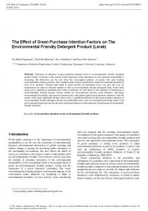
immediately below the industrial sediments. The detailed route of the Łagiewnicka Route is presented in Fig. No. 1. Since the tunnel construction work was done using the cut-and-cover method, at the section of the Łagiewnicka Route concerned, an attempt was made to assess the impact of the earthworks on the behaviour of the anthropogenic soils and the negative impact of the excavation on the John Paul II Centre in Kraków. The determination of the geotechnical parameters of the land enabled the construction of a numerical model which made it possible to determine the impact of the excavation on the behaviour of the land in its neighbourhood. The analyses served the purpose of presenting the results of the land deformation parameters on the area of the “White Seas”.
2 Location and geological engineering conditions The places where the samples were collected are marked on the satellite image with the Łagiewnicka Route marked thereon (Fig. 1). Besides, archival studies done by the Soil – Structure Interaction Division, Cracow University of Technology, for the area were also used.
Fig. 1. Location of the “Łagiewnicka Route” course in the area of Solvay Sodium Plant landfill, also indicating the location of boreholes O1, O2, O3 and O4 [4,5]
The geological structure of the terrain, together with a description of the formation of the production sedimentation tanks of the Solvay Sodium Plant in recent years, was discussed in several papers [1,2,3,6]. In the subsoil layer, there are quaternary soils (sand and gravel alternating with cohesive soils, mainly dusts) which are laid out directly on the tertiary formations represented by Miocene silt. Above the indigenous soil, there is waste generated during the former production of the Solvay Sodium Plant in Kraków. The 2
E3S Web of Conferences 36, 03006 (2018) https://doi.org/10.1051/e3sconf/20183603006 BIG 2018
production generated waste which was stored in whole, in the form of suspended matter, in sedimentation tanks. The tanks covered a total area of more than 30 ha. The height of the stored waste was up to 20m. Based on the field geotechnical and land-surveying studies which were done and an analysis of data in the writings [2,3,4], the following cross-sections were made: transverse A-A and longitudinal B-B for the section of the tunnel located on the area of the “White Seas” in Łagiewniki. The cross-sections took account of the geometry of the tunnel. Besides, it was proposed to extend the tunnel walls to locate them on the load-bearing layers.
Fig. 2. Transversal cross-section A-A
Fig. 3. Longitudinal cross-section B-B
The cross-sections and the specified parameters of the subsoil served, ultimately, to develop a numerical model with which a numerical analysis was done concerning the next stages of tunnel construction. The analysis takes account of the impact of the excavation, at the construction stage, on deformation of the subsoil in the neighbourhood of the John Paul II Centre in Kraków.
3 Material and Methodology The soil for laboratory tests was collected from two test boreholes O2 and O3. In both of them, below the gravel layer, anthropogenic soils were found, mainly in a semi-compact and plastic condition. No ground water table was found in the boreholes. The water content of the soil in the profile varied. After it had been transported to the laboratory, the soil was cold stored at a temperature of 5°C until the samples were formed and the tests were done. The tests were done on samples with natural water content. The test range was selected on the basis of the parameters necessary for developing a numerical model of digging the Łagiewnicka Route tunnel.
3
E3S Web of Conferences 36, 03006 (2018) https://doi.org/10.1051/e3sconf/20183603006 BIG 2018
4 Results and analysis The tests were done at the Laboratory Soil – Structure Interaction Division, Cracow University of Technology. The averaged results of the physical parameters which were used in the development of the numerical model are presented below. 4.1 Physical properties of the soil The results of the physical parameters, i.e. bulk density, particle density, water content, porosity and the degree of saturation are presented in Table No. 1. Table 1. Physical parameters of the soil on the area of the “White Seas” in the natural condition. Bulk density [g/cm3]
Water content [%]
Particle density [g/cm3]
Porosity [-]
Degree of saturation [-]
1,45
75
2,64
0,65
0,79
FSa/siSa
1,95
21
2,65
0,39
0,64
Clay
2,05
34
2,68
0,43
1,21
Sample Anthropogenic Soil
4.2 Mechanical properties of the anthropogenic soil 4.2.1 Shear strength The tests of shear strength setting the critical angle of repose and coherence, were done in the shearing test apparatus. The compression stresses were applied of 50, 100, 150 and 200 kPa, accordingly. The shear results are presented in Fig. No. 4.
Fig. 4. Results of the shearing test.
Ultimately, based on tests for anthropological tests, the critical angle of repose was about 5 degree and the coherence about 8 kPa. The tests were done for 5 soil samples totalling 20 tests from each borehole.
4
E3S Web of Conferences 36, 03006 (2018) https://doi.org/10.1051/e3sconf/20183603006 BIG 2018
4.2.2 Consolidation Due to the use of the Modified Cam-Clay numerical model in the Midas GTS NX software, consolidation tests were done with the use of a oedometer. The test results for the representative sample with the specified path are presented in Fig. No. 5.
Fig. 5. Results of oedometric tests.
The figures for the primary deformation modules for the samples were 4÷9 MPa. The secondary deformation module was between 12 and 18 MPa. 4.2.3 Dynamic parameters of the soil The setting of the dynamic parameters of the soil base from the area of the “White Seas” was the subject of the studies done in 2017. The results are presented in paper [3]. The dynamic module figures of the base in its natural condition, i.e. the module of nondilatational strain G was set at 12-20 MPa. The module figure changed together with the depth in the test borehole. In a comparison of the results of the transversal and longitudinal wave, the Poisson ratio was set for soil with natural water content which is 0.35÷0.39 [3]. The parameters are presented in Table No. 2.
5 Numerical Analysis The numerical analysis was done with the assumption that the tunnel would be constructed in the open excavation technology. Such technology for the construction of tunnels all alongside the “Łagiewnicka Route” was adopted at the stage of identifying the contractor for the route [4]. The considerable overburden in the area of the “White Seas” of even 12m above the upper tunnel plate caused a problem in the protection of the excavation walls along the section concerned. Due to the close proximity of the John Paul II Centre, an analysis was done of protecting the tunnel excavation, in three alternatives. Also, an analysis of stability of the alternatives was done to see whether the technology of doing the work would not have a negative effect on the location of the John Paul II Centre in Kraków. The Modified Cam-Clay model was applied, which was based on the theory of resilience and plasticity theory with enhancement [7]. Non-linear behaviour is represented by an increase in the bulk modulus during the application of pressure in the material. Material plastification is applied in the material together with the destruction surface whose changes depend on the hardening or the softening of the material. Figure 6 presents a diagram of the relationship between the changes in the sample volume conditioned by the pressure in the MCC model.
5
E3S Web of Conferences 36, 03006 (2018) https://doi.org/10.1051/e3sconf/20183603006 BIG 2018
Fig. 6 Relationship between sample volume and pressure in the MCC model [8]
Detailed information on the assumptions in the MCC model for the soil can be found in the records [8,9,10]. Figure No. 7 presents the model with a simulation of the construction work staging. The symmetrical part of the structure was taken account of. The analysed area was implemented in the Midas GTS NX programme based on the finite element method.
Fig. 7. Numerical model for the area, with staging No. 1-10
The geometry of the model covered an area of 32.5m in width and 35m in depth. The model was discretised with quadrangular finite elements of 0.5m. Non-displaceable boundary conditions were applied at the model’s base. The vertical edges were blocked horizontally. The geotechnical layer with the thickness of 24 m, made of anthropological soil, was modelled with the MCC model. At the depth of between 24m and 30m, a clay layer was implemented in the MC model. The silt layers below 30m, were modelled with the MC model. Larssen type walls modelled with beam elements were selected as the encasing of the first excavation. The thrust depth was set at 14m below the terrain level. Cavity walls made of C30/37 concrete with the thickness of 0.8m were taken as the encasing of the other tunnel. The upper and lower plates with the thickness of 0.6m were modelled with beam elements. The contact was included between beam elements and the geotechnical layers. The following calculation alternatives were applied: Alternative I: checking the stability of the excavation to the level of the tunnel’s upper plate Alternative II: designing the wall protecting the excavation in the form of a Larssen 755 wall.
6
E3S Web of Conferences 36, 03006 (2018) https://doi.org/10.1051/e3sconf/20183603006 BIG 2018
Alternative III: application of a vertical encasing of the planned tunnel made of a concrete cavity wall and the making of the excavation together with the construction of the tunnel’s upper and lower plates. Covering the tunnel with anthropogenic soil. The parameters of the materials applied in the numerical simulations are presented in Table No. 2.
Table 2. Materials parameters used in numerical simulations. Material:
Material 1
Material 2
Material 3
Model: E [MPa] ν [-] γ[kN/m3] φ [○] c [kPa] K0 [-] λ κ M
MCC 9.27 0.37 14.22 5 8 0.58 0.002 0.001 0.179
MC 80 0.30 21.58 20 35 0.43 -
MC 80 0.30 21.09 26 65 0.43 -
Steel Larssen 755 Elastic 210000 0.30 78.50 1.0 -
Concrete C30/37 Elastic 33000 0.20 24.00 1.0 -
Numerical simulations for alternative I demonstrated that an unprotected excavation with appropriate inclination of the slopes is only possible at the inclination of 1:4.5. Due to a low efficiency of this solution, it is recommended to protect the excavation in accordance with alternatives II and III. Figure 8 presents the results of the initial inclination of the slopes of 1:1 (Fig. 8a), and the inclination of 1:4.5 stabilising the excavation slope (Fig. 8b).
Fig. 8. a) Slip surface for the inclination alternative 1:1 and FoS=0.54 b) Slip surface for the inclination of 1:4.5 and FoS=1.05
The numerical simulations for alternatives II and III were based on the following stages (Fig.7): Stage 1: thrusting a sheet pile to the depth of 14m below the terrain level, Stages 2,3,4,5: making of an excavation to the depth of 3m, 6m, 9m, 11.5m below terrain level, with the protection of the wall with ground anchors, Stage 6: making of a cavity wall to the depth of 18.5 m from the excavation level, Stage 7: construction of the upper plate, Stage 8: extracting the soil under the plate, Stage 9: construction of the tunnel’s lower plate, Stage 10: covering the tunnel with anthropogenic soil. With the application of appropriate support of the cavity wall, the analysis demonstrated the overall effectiveness of the alternative which was adopted, as a result of which the land in the neighbourhood of the CJPII will not be subject to excessive deformations.
7
E3S Web of Conferences 36, 03006 (2018) https://doi.org/10.1051/e3sconf/20183603006 BIG 2018
6 Conclusions The paper presents the results of field studies and laboratory studies and tests of the parameters of soils from the production waste heap on the area of the defunct Solvay Sodium Plant in Kraków. The results of laboratory tests together with the results of field studies done to identify the base for the John Paul II Centre (CJPII) project in Łagiewniki, in Kraków served the purpose of developing a numerical model and analysing the stage of construction work on the Łagiewnicki Route tunnel on land deformation in the immediate neighbourhood of the John Paul II Centre. The area concerned is characterised by low geotechnical parameters. This is confirmed by the Soil – Structure Interaction Division own studies which were part of preparation of the execution documentation for the Łagiewnicka Route tunnel on the area of the “White Seas” [4]. Due to low soil strength parameters, it can finally be concluded that the land cannot be used as the soil bearing substrate to locate the future road project there. Besides, the results of the soil numerical model, which take account of the base parameters specified on the basis of the studies and tests, point to the need to protect the excavation to counteract the negative impacts on the John Paul II Centre.
6 References 1.
I. Krzak, Zagospodarowanie terenów poprzemysłowych Krakowskich Zakładów Sodowych „Solvay”, Problemy Ekologii Krajobrazu, Tom 17, s.283÷287 (2005) 2. B. Czado, Analiza nośności pali fundamentowych na podstawie polowych badań gruntów sondą statyczną, Rozprawa doktorska, Biblioteka Politechniki Krakowskiej (2014) 3. E. Pilecka, J. Zięba “Preliminary studies of the dynamic stiffness modules of soil samples from the Solvay Sodium Plant waste landfill in Krakow”, E3S Web of Conferences (2017) 4. http://trasalagiewnicka.krakow.pl/ 5. http://www.geoportal.gov.pl// 6. W. Sroczyński, Perspektywy zagospodarowania tzw. ʺbiałych Mórzʺ na terenach po byłych krakowskich Zakładach sodowych ʺSolvayʺ Komisja Krajobrazu Kulturowego PTG s.423÷430 (2008). 7. A. M., Britto, M. J. Gunn, Critical state soil mechanics via finite elements, Ellishorwood Limited (1987) 8. Midas GTS NX, Manual specification. Materials, (2016) 9. T. Godlewski, T. Szczepański, Metody określania sztywności gruntów w badaniach geotechnicznych, Instytut Techniki Budowlanej, Warszawa (2015) 10. R. I., Borja, Cam-clay plasticity, Part II: Implicit integration of constitutive equation based on a nonlinear elastic stress predictor, COMPUT METHOD APPL M, Vol. 88, Issue 2, pp. 225-240 (1991)
8