Key words: Automobile nut, real time system, image processing algorithms, pneumatic components, vision system, circle algorithm, visual abilities, mechanical structure, digital image ..... Pdf Image. Processing techniques for Machine Vision. Biedl, T., M. Hasan, J.D. Horton, A.L. ... Fundamentals of Machine Vision. 1st Edn.
Journal of Computer Science 8 (4): 528-532, 2012 ISSN 1549-3636 © 2012 Science Publications
In-Process Vision Inspection Systems for Sorting using Image Processing Techniques 1
Latha, J. and 2N. Devarajan Department of EEE, Faculty of Engineering, Avinashilingam University for Women, Coimbatore, Tamilnadu, India 2 Faculty of Electrical Engineering, Government College of Technology, Coimbatore, Tamilnadu, India 1
Abstract: Problem statement: Machine vision system is based on digital image processing and is found to be the best sensor detection as its operation is similar to the human eye. The purpose of machine vision is the desire to provide real time machines with visual abilities. Approach: A real time system is developed and is interfaced with the mechanical structure to be used in automobile industry. Dynamic thersholding is used and image pre-processing techniques are considered and implemented namely ellipse and circle algorithm. Results: The developed machine vision system consists of a mechanical structure, DIO card for communication and pneumatic components. Conclusion: The proposed model is tested on real time for segregation and mix up of automobile nut samples. Key words: Automobile nut, real time system, image processing algorithms, pneumatic components, vision system, circle algorithm, visual abilities, mechanical structure, digital image images, such as lenses to focus the desired field of view onto the image sensor and suitable, often very specialized, light sources, Input / Output hardware (e.g., digital I/O) or communication links (e.g., network connection or RS-232) to report results. A synchronizing sensor for part detection (often an optical or magnetic sensor) to trigger image acquisition and processing and some form of actuators to sort, route or reject defective parts, a program to process images and detects relevant features. Naturally, capturing an image, possible several for moving processes is a pre-requisite for analyzing a scene. In many cases these images are not suited for immediate examination and require pre-processing to change certain sizing specific structures. In most cases it is at least approximately known which image areas to be have analyzed, i.e., the location of a mark to be read or a component to be verified. These are called Regions Of Interest (ROI) (sometimes Area Of Interest or AOI). Of course, such a region can also comprise the entire image if required.(Ramli et al., 2008). A process called segmentation is used to isolate these objects. Because of the essential role of this step, various segmentation methods are used in machine vision. Once the objects have been segmented, characteristic properties can be computed, such as area, perimeter, position, orientation, distance from each other, similarity to predefined
INTRODUCTION Machine vision encompasses computer science, optics, mechanical engineering and industrial automation. Unlike computer vision which is mainly focused on machine-based image processing, machine vision integrates image capture systems with digital input/output devices and computer networks to control manufacturing equipment such as robotic arms. Manufacturers favor machine vision systems for visual inspections that require high-speed, high-magnification, 24-h. operation and/or repeatability of measurements. The aim of a machine vision inspection system is typically to check the compliance of a test piece with certain requirements, such as prescribed dimensions, serial numbers and presence of components the complete task can frequently be subdivided into independent stages, each checking a specific criterion. These individual checks typically run according to the following model: Image Capture, Image Preprocessing, Definition of one or more (manual) regions of interest, Segmentation of the objects, Computation of object features, Decision as to the correctness of the segmented objects .A typical machine vision system will consist of most of the following components: One or more digital or analogue cameras (blackand-white or color) with suitable optics for acquiring
Corresponding Author: Latha, J., Department of EEE, Faculty of Engineering, Avinashilingam University for Women, Coimbatore, Tamilnadu, India
528
J. Computer Sci., 8 (4): 528-532, 2012 patterns (e.g., for character recognition). Finally, these properties are checked for compliance with the nominal values of the inspection task. The major machine vision applications is from defect inspection of semiconductor wafers to notifying a painting robot which style of vehicle is coming next-and countless others. The typical applications are gauging/measurement, identification, optical character recognition, presence verification print inspection, surface inspection, colour analysis, code reading (Bolhouse, 1993; Davies, 2005; Gonzalez and Woods, 2002). A digital camera has almost the same structure as that of a conventional (analog) camera, but the difference is that a digital camera comes equipped with an image sensor called a CCD. The image sensor is similar to the film in a conventional camera and captures images as digital information. CCD stands for Charge coupled device, which is a semiconductor element but converts images into digital signals. A photoelectric sensor can detect presence/absence of a target of a specified size in a specified location .Here in the in-process vision system, the image of the nut is captured on the fly (without stopping) and dynamic algorithm was indigenous developed to sort the mix up in nut and the template matching is not adopted for this type of inspection. Image pre-processing techniques (Alberto and Tosunoglu, 2000; Liedtke, 1992; Frayman et al., 2006) are considered and implemented; namely ellipse algorithm and circle algorithm (Biedl et al., 2002; Aken, 1984; Burr et al., 2005). In other words, machine vision is the desire to provide machines and robots with visual abilities. The main objective of the research presented in this study is to develop real time system that can interface with the mechanical structure to be used in automobile industry.
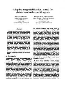
Fig. 1: Flow chart of the operation of nut sorting algorithm
Fig. 2: Presence of component Each nut will have specified number of alpha numerical characters punched on the top surface as per the model/type of nut. The vision algorithms are written using dynamic image processing techniques so that the number of logo’s and the thread pitch are inspected and sorted according to the selected model of the nut. The nuts will be segregated automatically to accept and reject bins with the help of PLC and mechanical arrangements.
MATERIALS AND METHODS
Presence of component: The nut moves on the conveyor and the CCD camera itself is used as the component sensor. To identify the presence of the nut in the camera frame the thresholding range of 95 is set for the frame band of y axis (20-700) and x axis (400630). The above mentioned frame band will have full of black pixels by default; this will turn into white pixels if the nut enters that band. As soon as the white pixel is detected the camera captures that particular frame. This threshold limit is set to 95 is fixed immaterial of the nut size passing through the image frame. The camera takes continuous images at 60 frames per second rate and one accurate image is selected automatically for processing as shown in the Fig. 2.
The objective of this work is to sort the nuts being manufactured in an industry with respect to mix up of different logo punched on the top surface of the nut, thread pitch and missing operation (No thread). These nuts are manufactured in a automobile ancillary manufacturer and will have the logo mark punched with alpha numerical characters on the top surface which represents different specification and customer needs. The nuts are sorted Fig. 1 depending upon the number of logo’s and the orientation of the alpha numerical characters. The camera is mounted at an inclined angle of 300-450 so that the top surface of the nut and the threaded portion of the nut can be captured in a single image frame. The image of the nuts is captured by the camera when they are moving on the conveyor continuously at a speed of sixty nuts per minute.
Thresholding: In this online process dynamic thresholding is applied to the converted grey scale image to get the binary data. The user chooses lower and upper threshold values to process the histogram. If 529
J. Computer Sci., 8 (4): 528-532, 2012 a pixel is inside of this range, it is assigned an "inside" value. Otherwise it is assigned an "outside" value. So, thresholding may be viewed as an operation that involves tests against a function Eq.1: T = T[x, y, p(x, y), f (x, y)]
(1)
where, f (x, y) is the grey level of point (x, y) and p(x, y) denotes some local properties of this point,e.g, the average grey level of a neighbourhood. The actual part of thresholding consists of setting background values for pixels below a threshold value T and a different set of values for the foreground. A thresholded image (Bolhouse, 1993; Gonzalez and Woods, 2002; Freeman 1988; Parker, 2010) g (x, y) is defined as Eq. 2: 0 if f ( x ) < T g (x) = 1 otherwise
Fig. 3: Center point of the inner and the outer ellipse
(2)
Image frame: The image frame is a known and declared variable and is equal to the resolution of the CCD camera we have used a 640×480 resolution camera in this nut sorting inspection system. The centre point of the image frame is known 3 and 4 by default and will be used as reference point to find out the approximate centre point of the nut from the dynamically acquired image Eq. 3 and 4:
Fig. 4: Circumferences of the ellipse
Xo = W/2 Yo= H/2
The ellipse radii are determined using Eq.9-12: IXR = (IX2-IX1)/2
(9)
IYR = (IY2-IY1)/2
(10)
OXR = (X2-X1)/2
(11)
(3)
OYR = (Y2-Y1)/2
(12)
(4)
Alpha numeric character detection: The Area Of Interest (AOI) for vision inspection is in between the inner and the outer circumferences of the ellipse. Since the images are captured online and processing is done dynamically unwanted data’s are eliminated using predefined threshold values. The exact centre point Xc and Yc of the ellipse is known. To determine the starting point and ending point of the AOI and with the acquired centre point and radii we draw the inner and outer ellipse and mark it in red color using the RGB value. Straight line is drawn from center point with 00 towards the outer circumference of the ellipse to mark co-ordinates on the edges of the inner and outer circumferences which initiates the starting and ending points of AOI to determine the alphanumerical characters. To find the number of alphanumerical characters and match with selected type stored in the database Fig. 5. The starting angle being zero degree the algorithm is defined to start reading in the incremental form, the AOI is the white pixel area and the alpha numerical characters which are black in color. The algorithm will start from the ellipse centre point towards inner circumference starting at zero degree. The inner circumference is identified in red pixels.
Forming ellipse and determining the radii of the image: After finding the approximate center point of the frame the outer edges of the nut are identified as ellipse and the corresponding image processing ellipse algorithm is used Eq. 5-8: Xc = X1 + (X2-X1)/2
(5)
Yc = Y1+ (Y2-Y1)/2
(6)
NH = Y2-Y1
(7)
NW = X2-X1
(8)
Xc Yc represents the center point of the inner and the outer ellipse Fig. 3. To trace the inner and outer nut circumference respectively, the algorithm ensures the approximate centre point of the frame toward the left X, right X and top Y, bottom Y. It will mark points as soon as the first white pixel is detected and join the points. Similarly the algorithm ensures the edges of the frame towards the approximate centre point and as soon as it detects the white pixel it will stop further proceeding and join all the points to form the outer circumference for the nut image (Fig. 4). 530
J. Computer Sci., 8 (4): 528-532, 2012
Fig. 5: Selected nut
Fig. 7: Vision inspection software interface
(a)
Fig. 6: Threads pitch detection The first red pixel is taken as the first reference point and further continue to identify the next red pixel which is the outer circumference of the ellipse. The presence for the black pixel is the alpha numerical character which is in between these two red pixels. Identification of all characters is done for the complete circumference of the ellipse. The number of characters in the acquired image is compared with the selected type of nut in the database.
(b)
Threads pitch detection, missing and comparison: The next part of the sorting system is to identify the correct thread pitch of type 1.5-2.5mm pitch. Considering (XC, Y2) as the centre point, an angle of thirty to forty five degrees is read in the inner circumference of the ellipse Fig. 6. Even pitch distance between the black and white pixels are taken and the average value of this is considered to detect the pitch distance. The same data is used to compare for the mixup in the pitch for the selected model type (1.5-2.5 mm pitch) of the nut which is stored in the database. The correct thread pitch is allowed to fall in the selected bin which is further packed and sent for dispatch and the mix-up thread pitch will be segregated to the rejection bin. In the inner circumference if the black pixels are missing then it is assumed that the thread is missing.
(c)
(d)
RESULTS The proto type consists of 60 fps 640×480 CCD camera from “The Imaging Source”. Germany, for image captures and image acquisition 1394V IEEE card interface with the PC through PCI slot.
(e)
Fig. 8: (a) Camera (b) DIO (c) Control panel (d) Pneumatic components (e) Final proto type machine 531
J. Computer Sci., 8 (4): 528-532, 2012 REFERENCES
The control and communication module mainly consisted of Digital Input Output card (DIO) from Advantech. The image processing module mainly consisted of the vision inspection software. The software was responsible for both type recognition and mix up sorting Fig. 7. The overall system Fig. 8 of automatic nut sorting consists of two main parts, software system and the mechanical structure. The image-processing algorithm needs to be interfaced with the mechanical setup to control the movement of the conveyor and automatic segregation of the nuts. All the algorithms for image processing and communication is developed in VC++. This acts as the interface between the mechanical structure (conveyor and segregation mechanism) and the vision inspection system.
Alberto, M. and S. Tosunoglu 2000. Pdf Image Processing techniques for Machine Vision. Biedl, T., M. Hasan, J.D. Horton, A.L. Opez-Ortiz and T. Vinar, 2002. Searching for the center of a circle. Proceedings of the 14th Canadian Conference on Computational Geometry, (CCCG’02), Canada, pp: 137-141. Bolhouse, V., 1993. Fundamentals of Machine Vision. 1st Edn., S.N, United States, pp: 82. Liedtke, C.E., 1992. Machine vision applications in germany. Universitat Hannover. http://www.tnt.unihannover.de/papers/data/149/149_1.pdf Davies, E.R., 2005. Machine Vision Theory, Algorithms, Practicalities. 3rd Edn., Elsevier, Amsterdam, ISBN-10: 9780122060939 pp: 934. Freeman, H., 1988. Machine Vision: Algorithms, Architectures and Systems. Academic Press, Boston, ISBN-10: 0122667204 pp: 315. Gonzalez, R.C. and R.E. Woods, 2002. Digital image processing. 2nd Edn., Prentice Hall, Upper Saddle River,, ISBN-10: 0201180758, pp: 793. Aken, J.R.V., 1984. An Efficient Ellipse-Drawing Algorithm. IEEE Comput. Graph. Appli., 4: 24-35. DOI: 10.1109/MCG.1984.275994 Burr, M.A., A. Lauric and K. Mann, 2005. Searching for the center of an ellipse. Tufts University. http://citeseerx.ist.psu.edu/viewdoc/download?doi= 10.1.1.89.9102&rep=rep1&type=pdf Parker, J.R., 2010. Algorithms for Image Processing and Computer Vision. 2nd Edn., John Wiley and Sons, Indianapolis, ISBN-10: 0470643854, pp: 504. Ramli, S., M.M. Mustafa, A. Husain and D.A. Wahab, 2008. Histogram of Intensity Feature Extraction for Automatic Plastic Bottle Recycling System Using Machine Vision. Am. J. Environ. Sci., 4: 583-588. DOI: 10.3844/ajessp.2008.583.588 Frayman, Y., H. Zheng and S. Nahavandi, 2006. Machine vision system for automatic inspection of surface defects in aluminum die casting. J. Adv. Comput. Intell. Intelligent Inform., 10: 281-282.
DISCUSSION This prototype system was tested in real time. The main factor to key successful of the real time machine vision system is its processing techniques to analyze an image. The system was also tested with 1000 samples to find the feasibility. The most important thing in the classification stage, how the nuts can be extracted using designated extraction technique. The limitation of this real time system can be optimally tuned to operate for the size detection in the range of 100-250 mm. The speed of the system is the detection of each nut per second. This contributed to the reliability of the machine vision system and the nut images can be distinguished correctly by implementing the given technique in image processing. CONCLUSION The system consists of hardware and software engine was successfully built in engineering prototype as shown in Fig. 8. It was integrated with compact size of PC and assembled into mechanical structure. The whole system can be fixed into five building blocks of image acquisition, data transfer with DIO from PC to control panel board interfaced with the pneumatic components and connected to the mechanical system for loading and segregating the component for automatic functioning of the nut for sorting purpose. The core component of the machine vision system is the image processing techniques. Further work is in progress to improve the system by using ANN technique for sorting of nuts in real time condition.
532