materials Article
In Situ Elevated Temperature Testing of Fly Ash Based Geopolymer Composites Les Vickers 1 , Zhu Pan 2 , Zhong Tao 2 and Arie van Riessen 1, * 1 2
*
Geopolymer Research Group, John de Laeter Centre, Curtin University, GPO Box U1987, Perth WA 6845, Australia;
[email protected] Institute for Infrastructure Engineering, Western Sydney University, Penrith NSW 2751, Australia;
[email protected] (Z.P.);
[email protected] (Z.T.) Correspondence:
[email protected]; Tel.: +61-8-9266-7090
Academic Editor: Javier Narciso Received: 11 April 2016; Accepted: 30 May 2016; Published: 3 June 2016
Abstract: In situ elevated temperature investigations using fly ash based geopolymers filled with alumina aggregate were undertaken. Compressive strength and short term creep tests were carried out to determine the onset temperature of viscous flow. Fire testing using the standard cellulose curve was performed. Applying a load to the specimen as the temperature increased reduced the temperature at which viscous flow occurred (compared to test methods with no applied stress). Compressive strength increased at the elevated temperature and is attributed to viscous flow and sintering forming a more compact microstructure. The addition of alumina aggregate and reduction of water content reduced the thermal conductivity. This led to the earlier onset and shorter dehydration plateau duration times. However, crack formation was reduced and is attributed to smaller thermal gradients across the fire test specimen. Keywords: fly ash geopolymers; alumina aggregate; in situ thermal testing; fire testing
1. Introduction Geopolymers are inorganic materials produced by alkali activation of suitable amorphous precursors such as metakaolin, fly ash and volcanic ash. They are based on aluminate and silicate tetrahedra, which can combine to form a range of compositions [1–3]. Geopolymers are generally recognised as being superior to ordinary Portland cement (OPC) based systems with respect to thermal resistance. Changes occurring in OPC systems are considered to be irreversible after heating beyond 500 ˝ C. This is attributed to the dehydration of OPC systems with formation of calcium oxide. On rehydration of the heated material, calcium hydroxide is reformed, which is an expansive process leading to the formation of cracks and reduced strength [4,5]. In the case of OPC, this loss of water from the hydrates present results in the reduction of strength and consequent load bearing ability [6,7]. Contrastingly, the majority of the water in geopolymer systems is not chemically bound, but is present in the pore system. The ease of escape of this water during thermal exposure is dictated by the inter connectivity of the pore system [8]. Ma et al. [9] demonstrated the higher porosity content and increased permeability of fly ash based geopolymer pastes compared to OPC paste. The increased pore volume connectivity of geopolymers compared to OPC during high temperature exposure will markedly increase transport of water through the binder with associated reduced spalling [7,10]. The complex chemical composition of fly ashes and the resulting geopolymers results in the formation of new phases during alkali activation and on subsequent thermal exposure [11]. The effect of these new phases and their evolution during thermal exposure needs to be clearly understood [12–14]. To develop thermally resistant geopolymer systems based on fly ash, knowledge of the bulk chemical and phase compositions is required. Bulk chemical composition (from X-ray fluorescence Materials 2016, 9, 445; doi:10.3390/ma9060445
www.mdpi.com/journal/materials
Materials 2016, 9, 445
2 of 13
spectrometry) and crystalline phase composition (from quantitative X-ray diffraction) determination is necessary to arrive at the amorphous silicon to aluminium ratio (Si:Al) [15]. From a geopolymer synthesis perspective this amorphous Si:Al value is crucial to the development of thermally resistant fly ash geopolymer systems [16,17]. In order to optimise thermal properties, control of thermal expansion and retention/development of physical properties after elevated temperature exposure is desirable. The use of thermally stable filler material to optimise thermal properties is common place in other materials technology. Additionally the use of fibres to modify crack initiation and propagation mechanisms can play an important role in the optimisation of properties during thermal exposure. Silva et al. [18] used naturally occurring wollastonite fibres (aspect ratio of 10 to 20:1) to reinforce a metakaolin based geopolymer. Toughness of the system increased as fibre volume increased to 5% by volume. The wollastonite is compatible with the pH levels in geopolymer synthesis and a dense interfacial transition zone, matrix-fibre, was developed. Dias and Thaumaturgo [19] investigated the addition of basalt fibres (45 mm ˆ 9 µm diameter) to metakaolin based geopolymer and OPC pastes at 0.5% and 1% volume fraction. The basalt fibres were more efficient at reinforcing the geopolymer system than the OPC system. This could probably be related to the alkali initiated bond formation between fibre and matrix [20]. Polypropylene fibres are used sacrificially, melting and vaporising on exposure to elevated temperatures to form channels to facilitate water escape [21–23]. This results in reduced spalling tendencies of thermally exposed systems. The ability of geopolymer systems to give controlled water release, together with inherent heat resistance, very low smoke and toxic gas emissions indicates that fly ash based geopolymers will show improved fire resistance compared to OPC and organic binders. In the case of geopolymers and OPC, no incomplete combustion products are formed during a fire so flashover times are theoretically infinite. Organic polymers used as binders for fibre reinforcement in composites generate smoke (incomplete combustion products), which lead to flash over times of 10 to 25 min. Flashover is a phenomenon unique to compartment fires, where products of incomplete combustion collect at the ceiling and then ignite leading to total involvement of the compartment materials and signaling the end of human survivability. The time to flashover is the available escape time. The Federal Aviation Administration (FAA) has used time to flashover of materials in aircraft cabin tests as the basis for acceptance criteria for commercial aircraft cabin materials [24]. Pan et al. [25] compared two different Class F fly ashes in a geopolymer mortar (sand:fly ash = 3:1) using 50 mm diameter ˆ 100 mm high cylinders. They measured strength gains and losses after exposure to 800 ˝ C. The rate of temperature increase was 4.4 ˝ C per minute with a two hour residence at the target temperature followed by natural cooling in the furnace. One fly ashshowed strength gains after high temperature exposure whilst the other showed losses. They suggested that further geopolymerisation at high temperatures and/or sintering could lead to gains whilst damage due to thermal incompatibility arising from non-uniform thermal gradients led to strength losses. The following was suggested as a mechanism of geopolymer thermal degradation: 1. 2. 3.
Thermal incompatibility between matrix and aggregates Pore pressure effects Phase transformations
Kong and Sanjayan [26] investigated the effect of heat on geopolymer paste, mortar and concrete. Aggregates with different Coefficients of Thermal Expansion (COTE) were evaluated together with the influence of specimen size. They concluded that strength loss in geopolymer concrete at high temperature can be attributed to a mismatch in COTE between geopolymer paste and aggregate. Larger aggregate gave better strength retention. Larger samples showed lower strength retention, which was attributed to larger temperature gradients.
Materials 2016, 9, 445
3 of 13
Pan and Sanjayan [27] described the equipment used to measure in situ physical properties of geopolymer paste at high temperatures. The level of preload influenced the thermal expansion behaviour in terms of absolute strain, but did not affect any deflection points with respect to temperature. A glass transition temperature of 560 ˝ C for the paste system was determined. Above this temperature, significant viscous flow occurred as shown by the large strain increases (1200%) up to 680 ˝ C. Previous work [28] showed that when the silicon to aluminium, ratio was reduced below 2.0 for Collie fly ash geopolymers with the addition of 10% by volume of thermally stable fillers (α-alumina, mullite and wollastonite), improved thermal resistance was demonstrated. In this paper the work is extended with the use of high volume loadings of graded alumina together with a fibre tri-blend in the 1.82 Si:Al binder. High temperature in situ testing of this composite is described together with the outcomes of simulated fire testing. 2. Experimental Details 2.1. Materials The fly ash used in this work was sourced from the Collie Power Station, Western Australia. The compositional information has been detailed previously [28]. Table 1 shows the differences in bulk and amorphous molar Si:Al. The graded α-alumina with an Al2 O3 content >99 wt % was sourced from Doral Minerals, Rockingham, Western Australia. The graded sizes were selected and combined in ratios to enable processable composites to be utilised in specimen preparation. Wollastonite, NYAD MG, was sourced from NYCO Minerals, Willsboro, NY, USA. The alkaline activating solution was based on sodium silicate, PQ-D A53 (PQ Australia, Dandenong, Australia) and sodium hydroxide pellets (Rowe Scientific, Wangara, Australia). Deionised water was used to prepare sodium hydroxide solutions. Sodium based activation was selected to enable comparison with previous work. The composition of the PQ-D A53 is 44.1 wt % solids with a SiO2 :Na2 O modulus of 2. Adfil Ignis, monofilament polypropylene fibres with a melting point of 165 ˝ C, were sourced from Reoco Performance Fibres, Smeaton Grange, New South Wales, Australia. They were 6 mm long and 18 µm diameter with a tensile strength of 600 MPa. The basalt fibres used in this work had a melting point of 1050 ˝ C and were sourced from Technobasalt, Kyiv, Ukraine. They were 5 mm long and 18 µm diameter with a tensile strength of 2900 MPa. The surface of the basalt fibres was treated with 1% by weight of silane type size to improve handling characteristics. Table 1. Differences in bulk and amorphous Si:Al for Collie fly ash. Total Oxide (wt %)
Collie Fly Ash
SiO2 Al2 O3 Fe2 O3 CaO Bulk Si:Al molar Amorphous content, % Amorphous Aluminosilicates, % Amorphous Si:Al molar
51.38 26.90 13.20 1.74 1.62 54.00 36.29 1.15
2.2. Geopolymer Synthesis The geopolymer matrix was synthesised with a targeted Si:Al ratio of 1.82, a Na:Al ratio of 1.08 and a water content of 20 wt % using a sodium hydroxide/sodium silicate solution as the activating medium. The fly ash and activating solution were mixed in a planetary mixer for five minutes prior to the addition of graded aggregate and fibres, followed by a further five minutes mixing for paste and a further seven minutes for aggregate filled composite. Table 2 shows the formulations used
Materials 2016, 9, 445
4 of 13
in this work. The geopolymer reaction mixture was poured into moulds of the required geometry, Materials 2016, 9, 445 4 of 13 which were then vibrated to remove entrained air. The filled moulds were then sealed and cured this work. TheOn geopolymer reaction was poured moulds the required geometry, for 24 h at 70 ˝ C. removal from themixture curing oven mouldsinto were kept of sealed for 2 days at ambient ˝ C) prior which were toto remove entrained air. The filled moulds were then sealed and cured for temperature (23then ˘ 2 vibrated demoulding. 24 h at 70 °C. On removal from the curing oven moulds were kept sealed for 2 days at ambient temperature (23 ± 2 °C) of prior demoulding. Table 2. Formulations the to two mixtures (parts by weight) with total water content and alumina content at the bottom of the table. Table 2. Formulations of the two mixtures (parts by weight) with total water content and alumina content at the bottom of the table. Components C1.82PP Paste HTC 6A Composite Components C1.82PP 100.0 Paste Collie Fly Ash Collie Fly Ash Solution 100.039.5 Alkaline Activating Alkaline Activating Solution 39.5 0.15 Polypropylene Fibre Polypropylene Fibre 0.15 Basalt Fibre Basalt Fibre Wollastonite Wollastonite Alumina aggregate 3–5 mm Alumina aggregate mm Alumina aggregate3–5 1–2 mm Aluminaaggregate aggregate 0.2–0.5 1–2 mmmm Alumina Alumina aggregate 0.2–0.5 Additional water mm Additional water - 139.65 Total Parts by Weight Total Parts by Weight 139.6520 Water content, wt % Water content, wt vol% % 20 0 Alumina content, Alumina content, vol%
0
HTC 6A Composite 100.0 100.0 39.5 39.50.15 0.151.0 1.010.0 10.0 175.0 175.0 105.0 105.0 70.0 70.07.5 7.5 508.15 508.15 7.2 7.251.0 51.0
2.3. Mechanical Testing
2.3. Mechanical Testing
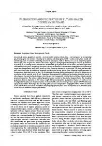
Compressive strength at athigh assessedbybyusing using a thermal steady-state Compressive strength hightemperatures temperatures was was assessed a thermal steady-state test test method while creep at high temperatures was assessed bybyusing method.All All the method while creep at high temperatures was assessed usingthe thetransient-state transient-state test test method. tests the were carried out using a MTS (Winchester, VA, USA) equipped with an electric split tube furnace tests were carried out using a MTS (Winchester, VA, USA) equipped with an electric split tube and extensometer fitted with alumina probes (Figureprobes 1). For(Figure hot strength tests, specimens furnace and extensometer fitted with alumina 1). For hot the strength tests, (without the specimens load) were heated at of a constant heating of 5 °C/min. Once the target any load) were (without heated atany a constant heating rate 5 ˝ C/min. Oncerate the target temperature was reached, temperature was reached, temperature was for around 2 h until reached the specimen the furnace temperature was the heldfurnace for around 2 h until theheld specimen temperature a steady temperature reached a steady state. Then the specimen was loaded until failure. The procedure of state. Then the specimen was loaded until failure. The procedure of the tests complied with RILEM the tests complied with RILEM TC 129HT [29]. For creep tests, the specimens were first loaded in 0.2σ, TC 129HT [29]. For creep tests, the specimens were first loaded in compression to a stress level of compression to a stress level of 0.2σ, where σ is the reference strength at room temperature prior to where σ is the reference strength at room temperature prior to heating. Then the stressed specimens heating. Then the stressed specimens were heated at a constant rate of 5 °C/min until failure were heated at a constant rate of 5 ˝ C/min until failure occurred. During heating, the strain was occurred. During heating, the strain was measured in the transient-state by a high-temperature measured in the transient-state by proposed a high-temperature The procedures extensometer. The procedures by RILEM extensometer. [30] were followed for these proposed types of by RILEM [30] were followed for these types of measurements. measurements.
Figure 1. High temperature testing arrangement.
Figure 1. High temperature testing arrangement.
Materials 2016, 2016, 9, 9, 445 445 Materials
of 13 13 55 of
2.4. Dilatometry 2.4. Dilatometry A DI-24 Adamel Limohargy, Roissy-en-Brie, France (alumina push rod dilatometer) was used to determine the thermal expansion and shrinkage on 4.7 mm diameter × 15 mm long was geopolymer A DI-24 Adamel Limohargy, Roissy-en-Brie, France (alumina push rod dilatometer) used to paste rods.the In thermal the caseexpansion of aggregate composites a 10 diameter mm × 12ˆmm × 22 long mm geopolymer rectangular paste block determine andfilled shrinkage on 4.7 mm 15 mm was cut from moulded cylinders. measurements were made range 25 to 1000 °C was at a rods. In the case of aggregate filledThe composites a 10 mm ˆ 12 mmover ˆ 22the mm rectangular block ˝ C at a to heating of 5 °C/min. A pre-load of 100 mN were was applied to the prior to heating allow cut fromrate moulded cylinders. The measurements made over thesample range 25 to 1000 heating dataoffrom shrinking samples to be in order comply with ASTM to E228-11 [31].from The rate 5 ˝ C/min. A pre-load of 100 mNcollected was applied to theto sample prior to heating allow data intersection of tangents the curve sections of large change wasE228-11 used to[31]. determine the inflexion shrinking samples to betocollected in in order to comply with ASTM The intersection of points in to thethe data [32]. in sections of large change was used to determine the inflexion points in the tangents curve data [32]. 2.5. SEM 2.5. SEM Scanning electron microscopy (SEM) was performed on a NEON 40EsB field emission SEM Scanning electronGermany) microscopy was performed on a Czech NEONRepublic). 40EsB fieldThe emission SEM coated (Zeiss, (Zeiss, Oberkochen, or(SEM) MIRA3 TECSAN (Brno, platinum Oberkochen, or MIRA3 TECSAN (Brno, Czech Republic). coated samples samples wereGermany) then imaged in the SEM with an accelerating voltage of The 5 kVplatinum using secondary electron were then imaged in the SEM with accelerating voltage of 5 kV using secondary electron (SE) or (SE) or back scattered electron (BSE)an imaging. back scattered electron (BSE) imaging. 2.6. Fire Testing 2.6. Fire Testing A custom designed electric furnace was used for the fire testing based on Australian Standard A custom electric furnace was used for the fire testing based on Standard AS1530.4. The designed equipment and methodology has been described previously byAustralian the authors of [33]. AS1530.4. The equipment and methodology has been described previously by the authors of [33]. The time versus temperature relationship of this fire curve is described by Equation (1). The time versus temperature relationship of this fire curve is described by Equation (1). T 345log10 8t 1 20 (1) T “ 345log10 p8t ´ 1q ` 20 (1) where T = temperature (°C), and t = time (min). where T = temperature (˝ C), and t = time (min).
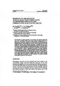
3. Results 3. Resultsand andDiscussion Discussion 3.1. Dilatometer Tests Tests 3.1. Figure22shows showsthe thethermal thermal expansion curves C1.82 (paste) 6A (composite). The Figure expansion curves for for C1.82 (paste) and and HTCHTC 6A (composite). The large ˝ large change in shrinkage at approximately 600 °C for the C1.82 specimen is caused by viscous flow change in shrinkage at approximately 600 C for the C1.82 specimen is caused by viscous flow and and sintering and by further sintering and formation of crystalline phases [16,34]. sintering and at 950at˝950 C by°Cfurther sintering and formation of crystalline phases [16,34].
Figure 2. Dilatometer curves for C1.82 paste (blue) and HTC 6A composite (green). The composite Figure 2. Dilatometer curves for C1.82 paste (blue) and HTC 6A composite (green). The composite curve shows both heating and cooling cycles as indicated by the direction of the arrows. curve shows both heating and cooling cycles as indicated by the direction of the arrows.
Materials Materials 2016, 2016, 9, 9, 445 445
66 of of 13 13
The dramatic reduction in shrinkage at 1000 °C associated with the addition of 51 vol % of Thealumina dramatictoreduction shrinkage at 1000 ˝ C associatedwas withreduced the addition 51 vol of graded graded the pasteinis clearly evident. Shrinkage fromof−5% to % +0.5%. The alumina to the paste is clearly evident. Shrinkage was reduced from ´5% to +0.5%. The smoothing out smoothing out of the composite curve and reduction in expansion range (relative to the paste) of the composite curve and reduction in and expansion range (relative to the paste) contributed to reduced contributed to reduced crack initiation propagation compared to the paste system. The weight crack initiation and propagation compared to the paste system. The weight (water) losses during the (water) losses during the heating cycle reflect the total water added (Table 3). The bulk of the water ˝ C as it heating cycle reflect the total water added (Table 3). The bulk of the water was lost up to 250 was lost up to 250 °C as it resided as free water in the pore system. resided as free water in the pore system. Table 3. Summary of in situ test results. Values in parentheses correspond to the least significant Table 3. of instandard situ test results. Values in left. parentheses correspond to the least significant figure figure in Summary the estimated deviation to the in the estimated standard deviation to the left.
As Cured Properties Density, g·cm−3Properties As Cured Compressive Density, strength, MPa ´3 g¨ cm Young’s Modulus,strength, GPa Compressive MPa Young’s Tested atModulus, GPa Tested at Compressive strength, MPa Compressive strength, MPa Young’sYoung’s Modulus, GPa Modulus, GPa Density,Density, g·cm−3 g¨ after 1000 °C1000 ˝ C cm´3 after Weight loss,% Weight after loss,%1000 after°C 1000 ˝ C Volume shrinkage,% after°C 1000 ˝ C Volume shrinkage,% after 1000
C1.82PP 1.98 (1) C1.82PP 24.5 (12) 1.98 (1) 9.8 24.5(5) (12) 9.8°C (5) 500 ˝C 500 38.7 (20) 38.7 (20) 2.1 (1) 2.1 (1) 1.89 1.89(1) (1) 19.4 19.4(1) (1) 11.8(11) (11) 11.8
HTC 6A 2.74 (2) HTC 6A 16.6 (19) 2.74 (2) 10.23 (50) 16.6 (19) 10.23 (50) 700 °C 700 ˝35.3 C (18) 35.3 (18) 2.6 (1) 2.6 (1) 2.73 (1) 2.73 (1) 2.9 (1)2.9 (1) 1.3 (1)1.3 (1)
3.2. 3.2. In In Situ Situ Compressive Compressive Strength Strength Testing Testing ˝ C were Testing Testing temperatures temperatures of of 500 500 and and 700 700 °C were selected selected from from the the dilatometer dilatometer curves curves(Figure (Figure2). 2). ˝ These temperaturesare are100 100 °C lowerthan thanthe theonset onsettemperature temperature viscous flow obtained from These test temperatures C lower of of viscous flow obtained from the the dilatometer curves. 3 summarises the results of situ the testing in situ while testingFigures while 3Figures 3 andthe 4 dilatometer curves. TableTable 3 summarises the results of the in and 4 show show the stress-strain stress-strain curves. curves. ˝ C °C Figure shows that thatthe theeffect effectofoftesting testing C1.82PP compared to ambient temperature Figure 3 shows C1.82PP at at 500500 compared to ambient temperature was was to agive a marked reduction in compressive stiffness by Young’s moduli of2.08 9.8 GPa, and to give marked reduction in compressive stiffness shown shown by Young’s moduli of 9.8 and 2.08 GPa, respectively, and aincrease ten-foldinincrease strain at maximum respectively, and a ten-fold strain atinmaximum load (0.003load and(0.003 0.029).and 0.029).
˝ C. Figure Figure 3. 3. C1.82PP C1.82PP compression compression test test curves curves undertaken undertaken at at ambient ambient and and 500 500 °C.
Materials 2016, 9, 445
7 of 13
Materials 2016, 9, 445
7 of 13
Materials 2016, 9, 445
7 of 13
Materials 2016, 9, 445
7 of 13
Figure 4. HTC 6A compression test curves, undertaken at ambient and 700 °C. ˝ Figure 4. HTC 6A compression test curves, undertaken at ambient and 700 C.
Figure 4. HTC 6A compression test curves, undertaken at ambient and 700 °C. The increase in compressive strength was from 24.6 MPa at 25 °C to 39.3 MPa at 500 °C. This
˝ambient Figure 4. HTC 6A compression test curves, undertaken andMPa 700 °C. The increase in compressive was from 24.6 MPa at 25atin Cthe to dilatometer. 39.3 atHowever, 500 ˝ C. This latter temperature is below thatstrength for onset of viscous flow as seen the latter The increase inthat compressive strength was from 24.6 MPa at 25 °C to 39.3 MPa at 500 the °C. This temperature is below for onset of viscous flow as seen in the dilatometer. However, applied applied stress of the test may be sufficient to reduce the activation energy for the viscous flow The increase in compressive strength was from 24.6 MPa at 25 °C to 39.3 MPa at 500 °C. This latter temperature is below that for onset of viscous flow as seen in the dilatometer. However, the stressprocess. of theThe testtenfold may be sufficient to reduce the activation energy for thethat viscous increase in strain at maximum load at 500 °C indicates viscousflow flowprocess. is latter temperature is below thatbe forsufficient onset of viscous flow asactivation seen in the dilatometer. the applied stress of the test may to reduce the energy for the However, viscous flow ˝ The tenfold increase in strain at maximum load at C indicateswith that resulting viscous flow is occurring. occurring. The viscous flow is consolidating the500 microstructure increases in applied stress of the increase test mayinbestrain sufficient to reduce theatactivation energy for viscous flow process. The tenfold at maximum load 500 °C indicates thatthe viscous flow is compressive A comparison of SEM images as cured (Figurein5)compressive and hot tested The viscous flow strength. is consolidating the microstructure withfrom resulting increases strength. process. TheThe tenfold increase inis strain at maximum load at 500 °C indicates that viscous flow in is occurring. viscous flow consolidating the microstructure with resulting increases (Figure 6) specimens confirms the occurrence of viscous flowhot during the (Figure compression test. A comparison SEM images from cured (Figure and tested 6) specimens confirms occurring. of The viscous is as consolidating the5)microstructure resulting in compressive strength. A flow comparison of SEM images from as curedwith (Figure 5) andincreases hot tested the occurrence ofstrength. viscous flow during theofcompression compressive A comparison SEM imagestest. fromduring as cured (Figure 5) and (Figure 6) specimens confirms the occurrence of viscous flow the compression test.hot tested
(Figure 6) specimens confirms the occurrence of viscous flow during the compression test.
Figure 5. C1.82PP as cured (AC) fracture surface image.
Figure 5. C1.82PP as cured (AC) fracture surface image. Figure 5. C1.82PP as cured (AC) fracture surface image.
Figure 5. C1.82PP as cured (AC) fracture surface image.
Figure 6. C1.82PP post compression test at 500 °C image.
Figure 6. C1.82PP post compression test at 500 °C image. Figure 6. C1.82PP post compression test at 500 °C ˝ image.
Figure 6. C1.82PP post compression test at 500 C image.
Materials 2016, 9, 445 Materials 2016, 9, 445 Materials 2016, 9, 445
8 of 13
8 of 13 8 of 13
Testing of HTC 6A at ˝700 °C (Figure 4) showed an increase in compressive strength from Testing of HTC 6A at 700 C (Figure 4) showed an increase in compressive strength from 16.6 MPa Testing of HTC at 700 °C (Figure 4) 35.3 showed increase strength from 16.6 MPa obtained at 6A ambient temperature to MPa.anThe changeinincompressive Young’s modulus is from obtained at ambient temperature to 35.3 MPa. The change in Young’s modulus is from 10.23 to 16.6 MPa obtained at ambient temperature to 35.3 MPa. Theatchange in Young’s modulus is from 10.23 to 2.57 GPa. SEM images, as cured (Figure 7) and tested 700 °C (Figure 8), again confirm that ˝ 2.57 GPa. images, cured 700 C 8), again confirm that viscous 10.23 to SEM 2.57 GPa. SEMasimages, as cured7) (Figure 7) andattested at (Figure 700 °C (Figure again confirm that viscous flow has occurred. The (Figure presence ofand the tested alumina enables the specimen to8),support the applied flow has occurred. The presence of the alumina enables the specimen to support the applied load viscous flow has occurred. The presence of the alumina enables the specimen to support the applied load whilst allowing additional viscous flow to occur after the point of maximum stress has load whilst allowing additional viscous flow to occur after the point of maximum stress has whilst allowing additional viscous flow to occur after the point of maximum stress has been passed. been passed. been passed.
Figure 7. HTC 6A as cured (AC) fracture surface image. Figure fracturesurface surfaceimage. image. Figure7.7.HTC HTC6A 6A as as cured cured (AC) (AC) fracture
Figure 8. HTC 6A post compression test at 700 °C image. Figure 8. HTC 6A post compression test at 700 °C image. Figure 8. HTC 6A post compression test at 700 ˝ C image.
3.3. Fire Testing Fire Testing 3.3.3.3. Fire Testing The failure requirements of the AS1530.4-2014 fire test can be summarised as follows: The failure requirements of the AS1530.4-2014 fire test can be summarised as follows: failureinrequirements of the AS1530.4-2014 fire test can be summarised follows: 1. The Failure relation to thermal insulation is determined when measurementasof temperature is 1. made Failurebyinthermocouples relation to thermal insulation is determined when measurement of on the unexposed face. The specimen is deemed to havetemperature failed when:is 1. Failure to thermal is determined when measurement ofhave temperature is made madein byrelation thermocouples on insulation the unexposed face. The specimen is deemed to failed when: Failure criteria 1 (FC1): The average the unexposed face when: of the test by(a) thermocouples on the unexposed face. Thetemperature specimen is of deemed to have failed (a) specimen Failure criteria 1 the (FC1): The average temperature the face of the test exceeds initial temperature by more thanof140 K; unexposed or specimen exceeds the initial temperature by more than 140 K; or (a)(b) Failure criteria 1 (FC1): The average temperature of the unexposed face of specimen Failure criteria 2 (FC2): The temperature at any location on the unexposed the facetest of the test (b) exceeds Failure criteria 2 (FC2): The temperature at any location on the unexposed face of the test the initial temperature by more than 140 K; or specimen exceeds the initial temperature by more than 180 K. specimen exceeds the initial temperature by more than 180 K. (b) Failure criteria 2 (FC2): The temperature at any location on the unexposed face of the test 2. Structural adequacy is defined as when a sample either collapses or when the deflection under a specimen exceeds initial byeither more collapses than 180 or K.when the deflection under a 2. given Structural is the defined astemperature when a sample loadadequacy exceeds that specified in AS1530.4. given load exceeds that specified in AS1530.4. Integrity failure canis show three 2. 3. Structural adequacy defined asfailure when criteria: a sample either collapses or when the deflection under a 3. Integrity failure can show three failure criteria: given exceedsflaming that specified in AS1530.4. load Continuous on the cold side surface; Continuous flaming on thefailure cold side surface; 3. Integrity failure can show three criteria:
‚
Continuous flaming on the cold side surface;
Materials 2016, 9, 445
9 of 13
Materials 2016, 9, 445 Materials 2016, 9, 445 ‚ Through
9 of 13
9 ofsizes 13 gaps into the furnace, as determined by standard gauges, exceeding the specified Throughingaps into the furnace, as determined by standard gauges, exceeding the sizes AS1530.4; specified Throughingaps into the furnace, as determined by standard gauges, exceeding the sizes AS1530.4; ‚ Ignition during the cotton wool pad test. specified in AS1530.4; Ignition during the cotton wool pad test. Ignition during the cotton wool pad test. The paste specimen C1.82PP showed extensive hot side cracking which appeared to have The paste specimen C1.82PP showed extensive hot side cracking which appeared to have undergone crack healing in some areas on cooling (Figure 9b).This may bewhich attributed to thetoability of The paste showed extensive side cracking appeared have undergone crack specimen healing in C1.82PP some areas on cooling (Figurehot 9b).This may be attributed to the ability of these unfilled systems to exhibit extensive viscous flow and sintering as seen in Figure 2. The cold undergone healing in someextensive areas on viscous cooling (Figure 9b).This may attributed to the ability these unfilledcrack systems to exhibit flow and sintering asbe seen in Figure 2. The coldof side (Figure 9a) formed wide cracks (2 mm)viscous which remained after cooling butindid not penetrate these unfilled systems to exhibit extensive flow and sintering as seen Figure 2. The coldthe side (Figure 9a) formed wide cracks (2 mm) which remained after cooling but did not penetrate the specimen thickness and therefore did (2 notmm) compromise the integrity of the specimen. 10 shows side (Figure 9a) formed wide cracks which remained afterofcooling but did Figure notFigure penetrate the specimen thickness and therefore did not compromise the integrity the specimen. 10 shows C1.82PP hot side post fire testing where delamination of areas is evident and attributed to differential specimenhot thickness and fire therefore didwhere not compromise the integrity specimen. 10 shows C1.82PP side post testing delamination of areasofisthe evident andFigure attributed to thermal expansion bulk in ofwhere the bulk test specimen. C1.82PP hot sideevents post in firethe testing delamination of areas is evident and attributed to differential thermal expansion events the of the test specimen. differential thermal expansion events in the bulk of the test specimen.
(a) (a)
(b) (b)
Figure 9. C1.82PP fire test image: (a) C1.82PP cold side after fire test; (b) C1.82PP hot side after fire Figure 9. C1.82PP fire test image: (a) C1.82PP cold side after fire test; (b) C1.82PP hot side after fire test. Figure 9. evidence C1.82PP of firecrack test image: C1.82PPSample cold side after firemm test; (b) C1.82PP sideexposed after fire test. Some healing(a) is evident. size is 300 × 300 mm withhot region Some evidence of crack healing is evident. Sample size is 300 mm ˆ 300 mm with region exposed to test. Some evidence of crack healing is evident. Sample size is 300 mm × 300 mm with region exposed to heat being 200 mm × 200 mm. heat being 200 mm ˆ 200 mm. to heat being 200 mm × 200 mm.
Figure 10. C1.82PP hot side close up showing lifting section attributed to differential thermal Figure 10. C1.82PP hotHealing side close up showing section attributed differential thermal expansion/delamination. of other cracks islifting also evident. that to this region is clearly Figure 10. C1.82PP hot side close up showing lifting section Note attributed to differential thermal expansion/delamination. Healing of other cracks is also evident. Note that this region is clearly visible in Figure 9b and has been enlarged 1.5×. expansion/delamination. Healing of other cracks is also evident. Note that this region is clearly visible in Figure 9b and has been enlarged 1.5×. visible in Figure 9b and has been enlarged 1.5ˆ.
In the case of the specimens with increased loadings of graded alumina, HTC 6A, many large In thewere case of the specimens withtesting. increased of graded alumina, 6A, many large air cavities evident prior to fire Theloadings cavities are attributed to air HTC entrainment which Incavities the case of the specimens with increased loadings of graded alumina, HTC 6A, many large air were evident prior to fire testing. The cavities are attributed to air entrainment which could not be removed by the vibrating table’s lack of power. These cavities were also evident after aircould cavities evidentbyprior to fire testing. The cavities are attributed to air entrainment which not were be removed the vibrating table’s lack of power. These also12a). evident fire testing. Very few, fine cold side cracks formed during the fire test cavities (Figureswere 11a and The after hot could not be removed by the vibrating table’s lack of power. These cavities were also evident after fire showed testing. Very few, fine coldformation side cracks(Figures formed11b during fireThis test may (Figures 11a and 12a). Thelow hotfire side similar fine crack andthe 12b). be attributed to the testing. Very few, fine cold side cracks formed during the fire test (Figures 11a and 12a). The hot side side showed similar finedemonstrated crack formation (Figures 11bcomposites. and 12b). This may bethermal attributed to the low thermal shrinkage values by these filled The higher conductivity thermal shrinkage values demonstrated by these filled composites. The higher thermal conductivity
Materials 2016, 9, 445
10 of 13
Materials 2016, 9, 445 of 13 showed similar fine crack formation (Figures 11b and 12b). This may be attributed to the low10 thermal Materials 2016, 9, 445 10 of 13 shrinkage values demonstrated by these filled composites. The higher thermal conductivity values for values for these systems also led to reduced thermal gradients across the thickness of the test these systems also led to reduced thermal gradients acrossgradients the thickness of the the test specimens and values for and these systems alsoshown led toby reduced thermal across thickness of the testthis specimens this is clearly the higher cold side temperatures attained during testing. is clearly shown by the higher cold side temperatures attained during testing. These lower thermal specimens this isgradients clearly shown by the to higher cold side attained during testing. These lowerand thermal are expected contribute to a temperatures reduced number of and smaller crack gradients are expected to contribute to a reduced number of and smaller crack formation. The use of These lower thermal gradients are expected to contribute to a reduced number of and smaller crack formation. The use of the fibre tri-blend would also have contributed to lower crack initiation and theformation. fibre tri-blend would also have contributed lower crack initiationtoand growth The use of the fibre tri-blend wouldtoalso have contributed lower crackrates. initiation and growth rates. growth rates.
(a) (a)
(b) (b)
Figure 11. HTC 6A fire test images: (a) HTC 6A cold side after fire test; (b) HTC 6A hot side after fire Figure 11. HTC 6A fire test images: (a) HTC 6A cold side after fire test; (b) HTC 6A hot side after fire Figure 11. HTC fire test images: (a) HTC 6A cold side after fire test; (b) HTC 6A hot side after fire test showing few6A minor cracks. test showing few minor cracks. test showing few minor cracks.
(a) (a)
(b) (b)
Figure 12. HTC 6A cold side: (a) after fire test and hot side; (b) after fire test showing fine cracks. Figure 12. HTC 6A cold side: (a) after fire test and hot side; (b) after fire test showing fine cracks. Figure 12. HTC 6A cold side: (a) after fire test and hot side; (b) after fire test showing fine cracks.
The plateau referred to in Table 4 is the “boiling front” which is attributed to the latent heat of The plateau referred to isinillustrated Table 4 is the “boiling which attributed to FC2 the latent heat of evaporation of referred water. This in Figure 13front” together withisisthe FC1 and The plateau to in Table 4 is the “boiling front” which attributed to thetemperature latent heat of evaporation of water. This is illustrated in Figure 13 together with the FC1 and FC2 temperature failure criteria. evaporation of water. This is illustrated in Figure 13 together with the FC1 and FC2 temperature failure criteria. failure criteria. Table 4. Summary of fire test results. Table 4. Summary of fire test results. Table 4. Summary of fire test results. Results C1.82PP
vol Results % alumina vol % alumina Calculated wtResults % water Calculated wt % water vol % Weight loss,alumina % Weight loss, % Calculated % water Start of plateau,wt min Weight min loss, % Start of plateau, Plateau duration, min Start of plateau, Plateau duration, min min −1 Plateau gradient, °C·min Plateau duration,−1min gradient, °C·min Cold Plateau side temperature at 120 min, ˝ ´1 Plateau gradient, C¨ min°C Cold side temperature at 120 min, °C Cold side temperature at 180atmin, °C ˝ C Cold side temperature 120 min, Cold side temperature at 180 min, °C Cold side at 180 min, ˝ C FCtemperature 1, min FC 1, min FC 1, min
C1.82PP 0 C1.82PP 0 20 020 12.0 12.0 20 37.4 12.0 37.4 32.5 37.4 32.5 0.65 32.5 0.65 247 0.65 247 279 247 279 279 87 87 87
HTC 6A HTC 51 6A HTC 6A 7.2 51 7.2 51 3.2 3.2 7.2 15.9 3.2 15.9 7.5 15.9 7.5 1.56 7.5 1.56 444 1.56 444 476 444 476 476 32.3 32.3 32.3
Materials 2016, 9, 445
11 of 13
Materials 2016, 9, 445
11 of 13
Figure 13.13.Cold readings. Figure Coldside sidetemperature temperature readings.
The measured weight values lower than total calculated values thespecimens specimenswere The measured weight loss loss values are are lower than thethe total calculated values asasthe ˝ were allowed to equilibrate at 23 °C and 50% ± 5% relative humidity for at least 28 days prior to fire allowed to equilibrate at 23 C and 50% ˘ 5% relative humidity for at least 28 days prior to fire testing. testing. The decreasing water content (indicated by weight loss in Table 4) as the alumina content The decreasing water content (indicated by weight loss in Table 4) as the alumina content increases will increases will lead to shorter plateau durations. Thermal conductivity also increases with decreasing lead to shorter plateau durations. Thermal conductivity also increases with decreasing water content water content but will only play a role up to the end of the dehydration plateau. but will only play a role up to the end of the dehydration plateau. The temperature gradient, across the 50 mm thick test slab, for paste is 16 and 12 °C/mm for the ˝ C/mm for the The temperature gradient, across mm test slab, paste is 16 and 12 are aggregate filled test slabs at 120 minthe into50 the test.thick At 180 min the for temperature gradients 16.6 and aggregate filled test slabs at 120 intothermal the test. At 180 min theaggregate temperature 16.6 and 12.8 °C/mm, respectively. Themin lower gradients for the filledgradients compositesare would 12.8 ˝suggest C/mm,lower respectively. The lower thermal gradients for the aggregate filled composites would thermal stresses are present during the test and together with the lower COTE would produce smaller cracks. actual differences between the cold with face temperature of paste suggest lowerfewer, thermal stresses are The present during the test and together the lower COTE would specimens aggregate filled composites are in the order of 180the to 200 °Cface at 120 min into the of testpaste produce fewer, and smaller cracks. The actual differences between cold temperature and 175 205 °C after min. Theare furnace 120 ˝and specimens andand aggregate filled180 composites in thetemperatures order of 180for to 200 C at180 120min minare into1049 the and test and 1110 °C, respectively, and were used as reference points for calculating the thermal gradient across ˝ 175 and 205 C after 180 min. The furnace temperatures for 120 and 180 min are 1049 and 1110 ˝ C, the slab. respectively, and were used as reference points for calculating the thermal gradient across the slab. The temperature increases between 120 and 180 min is in the region of 30 °C for both specimens. The temperature increases between 120 and 180 min is in the region of 30 ˝ C for both specimens. After the dehydration plateau has passed the specimens begin to heat up more rapidly depending After on thethe dehydration has passed specimens to heat upthermal more rapidly depending temperature plateau difference between thethe furnace and thebegin cold side and the conductivity of on thethe temperature difference between the furnace and the cold side and the thermal conductivity slab. The rate of furnace temperature increase is reduced from 104 °C in 30 min (208 °C/h) ˝ in 30 min (208 ˝ C/h) of thebetween slab. The of furnace temperature reduced the rate 30 and 60 min test period to 61increase °C in 60ismin for thefrom 120 to104 180 C min test period. The ˝ thermal theperiod systems willCalso bemin changing thetotemperature and thermal the between the 30conductivity and 60 minoftest to 61 in 60 for theas120 180 min testincreases period. The plateau of gradient is an indication of the specimen thermal conductivity (higher plateau gradient is conductivity the systems will also be changing as the temperature increases and the plateau gradient related to higher thermal conductivity). The rate of furnace temperature increase appears to have is an indication of the specimen thermal conductivity (higher plateau gradient is related to higher more influence on cold face temperature than thermal conductivity as shown by the narrow thermal conductivity). The rate of furnace temperature increase appears to have more influence on temperature increase range of around 30 °C (between 120 and 180 min), across both samples (which cold face temperature than thermal conductivity as shown by the narrow temperature increase range will have˝ differing thermal conductivities). of aroundIncreasing 30 C (between 120 and 180 min), across both samples (which will have differing thermal the volume of alumina in the composites has a marked effect on their response to the conductivities). fire test. The rapid increase in cold side temperature following the early commencement of the Increasing volume of alumina the composites has a compared marked effect on their response dehydrationthe plateau gives relatively in short fire ratings (FC1) to paste samples. The to the fire test. The rapid increase sideconductivity temperature the(see early commencement of the addition of alumina increasesin thecold thermal of following the composite Table 4) and the water content plateau reduces gives as therelatively alumina content increases a lower paste content). In a The separate dehydration short fire ratings (due (FC1)tocompared to paste samples. addition experiment drying of thermal the composite at 100 andof250 also reduced theTable thermal conductivity which of alumina increases the conductivity the°Ccomposite (see 4) and the water content supported the effect of reduced water content. This reduction in water content means that less reduces as the alumina content increases (due to a lower paste content). In a separate experiment required to supply the latent evaporation of the water corresponding to a shorter dryingenergy of theiscomposite at 100 and 250 ˝ C heat also of reduced the thermal conductivity which supported the duration of the dehydration plateau. effect of reduced water content. This reduction in water content means that less energy is required to supply the latent heat of evaporation of the water corresponding to a shorter duration of the dehydration plateau. Whilst the filled composite gave a reduced fire rating, their integrity, as shown by the formation of only small cracks, even after a 3 h fire exposure time, is maintained. This is despite this system
Materials 2016, 9, 445
12 of 13
reaching a cold side temperature of 476 ˝ C. Examination of the hot side of this specimen also showed minimal cracking. The brown colouration after firing was lighter than the paste due to the lower percentage of binder, and hence less oxidisable iron, in the composites. 4. Summary Preloading of samples during high temperature exposure initiated viscous flow at lower temperatures than seen in unloaded tests, such as the dilatometer. Careful consideration in designing for the use of geopolymers at elevated temperatures is required so that viscous flow is not initiated during service. The use of thermally stable filler/aggregate (α-alumina in this case) has led to viscous flow occurring at higher temperatures than in paste specimens. The use of alumina filler in conjunction with a fibre tri-blend has enabled the production of composites showing good integrity after fire testing for 3 h. This has been at the expense of the fire rating defined in AS1530.4 due to the increased thermal conductivity imparted by the added alumina. However, observed cracking on hot and cold faces was minimal. Increasing additional water content may extend the fire rating, but care must be taken that as cured physical properties are not overly reduced. The high thermal conductivity shown by these composites may be beneficial when rapid heat dissipation from components is required. It may also be beneficial in the response to thermal shock loading where reductions in thermal gradients are advantageous. The selection of alternative fillers to alumina, added as a total replacement or as part of a blend with alumina, may be beneficial in increasing the fire rating without impacting on the integrity of the composite. Author Contributions: Les Vickers and Arie van Riessen conceived and designed the experiments; Les Vickers and Zhu Pan performed the experiments. Zhong Tao and Zhu Pan provided equipment and supported the in situ testing as well as contributing to data analysis. Les Vickers wrote the paper with support from the other authors. Conflicts of Interest: The authors declare no conflict of interest.
References 1. 2.
3. 4. 5. 6.
7. 8. 9. 10. 11. 12.
Davidovits, J. Geopolymers and geopolymeric materials. J. Therm. Anal. 1989, 35, 429–441. [CrossRef] Barbosa, V.F.F.; Mackenzie, K.J.D.; Thaumaturgoa, C. Synthesis and characterisation of materials based on inorganic polymers of alumina and silica: Sodium polysialate polymers. Int. J. Inorg. Mater. 2000, 2, 309–317. [CrossRef] Palomo, A.; Grutzeck, M.W.; Blanco, M.T. Alkali activated fly ashes: A cement for the future. Cem. Concr. Res. 1999, 29, 1323–1329. [CrossRef] Arioz, O. Effects of elevated temperatures on properties of concrete. Fire Saf. J. 2007, 42, 516–522. [CrossRef] Alarcon-Ruiza, L.; Platret, G.; Massieu, E.; Ehrlacher, A. The use of thermal analysis in assessing the effect of temperature on a cement paste. Cem. Concr. Res. 2005, 35, 609–613. [CrossRef] Van Riessen, A.; Rickard, W.; Sanjayan, J. Thermal properties of geopolymers. In Geopolymers: Structure, Processing, Properties and Industrial Applications; Provis, J.L., van Derventer, J.A.S., Eds.; Woodhead Publishing Ltd.: Cambridge, UK, 2009; pp. 315–342. Kong, D.; Sanjayan, J.G.; Sagoe-Crentsil, K. Comparative performance of geopolymers made with metakaolin and fly ash after exposure to elevated temperatures. Cem. Concr. Res. 2007, 37, 1583–1589. [CrossRef] Zhao, R.; Sanjayan, J. Geopolymer and Portland cement concretes in simulated fire. Mag. Concr. Res. 2012, 63, 163–173. [CrossRef] Ma, Y.; Hu, J.; Ye, G. The pore structure and permeability of alkali activated fly ash. Fuel 2013, 104, 771–780. [CrossRef] Bakharev, T. Thermal behaviour of geopolymers prepared using class F fly ash and elevated temperature curing. Cem. Concr. Res. 2006, 36, 1134–1147. [CrossRef] Rickard, W.D.A.; Kealley, C.S.; van Riessen, A. Thermally induced microstructural changes in fly ash geopolymers: Experimental results and proposed model. J. Am. Ceram. Soc. 2015, 98, 929–939. [CrossRef] Krivenko, P. Development of alkaline cements supported by theory and Practice. In Proceedings of the 4th International Geopolymer Conference, Saint Quentin, France, 29 June–1 July 2005.
Materials 2016, 9, 445
13.
14. 15. 16. 17.
18. 19. 20. 21.
22. 23. 24. 25. 26. 27. 28. 29. 30. 31.
32. 33. 34.
13 of 13
Kovalchuk, G.; Krivenco, P.V. Producing fire and heat resistant geopolymers. In Geopolymers; Structure, Processing, Properties and Structural Applications; Provis, J.L., van Deventer, J.S.J., Eds.; Woodhead Publishing Limited: Oxford, UK, 2009; pp. 227–266. Duxon, P.; Lukey, G.C.; van Deventer, J.S.J. The thermal evolution of metakaolin geopolymers: Part 2—Phase stability and structural development. J. Non-Cryst. Solids 2007, 353, 2186–2200. [CrossRef] Williams, R.P.; Van Riessen, A. Determination of the reactive component of fly ashes for geopolymer production using XRF and XRD. Fuel 2010, 89, 3683–3692. [CrossRef] Rickard, W.D.A.; Temuujin, J.; van Riessen, A. Thermal analysis of geopolymer pastes synthesised from five fly ashes of variable composition. J. Non-Cryst. Solids 2012, 358, 1830–1839. [CrossRef] Rickard, W.D.A.; Williams, R.; Temuujin, J.; van Riessen, A. Assessing the suitability of three Australian fly ashes as an aluminosilicate source for geopolymers in high temperature applications. Mater. Sci. Eng. A 2011, 528, 3390–3397. [CrossRef] Silva, F.J.; Mathias, A.F.; Thaumaturgo, C. Evaluation of the fracture toughness in poly (sialate-siloxo) composite matrix. Geopolymere 1999, 99, 97–106. Dias, D.P.; Thaumaturgo, C. Fracture toughness of geopolymeric concretes reinforced with basalt fibers. Cem. Concr. Compos. 2005, 27, 49–54. [CrossRef] Rill, E.; Lowry, D.R.; Kriven, W.M. Properties of basalt fiber reinforced geopolymer Composites. In Strategic Materials and Computational Design; John Wiley & Sons, Inc.: Hoboken, NJ, USA, 2010. Bilodeau, A.; Kodur, V.K.R.; Hoff, G.C. Optimization of the type and amount of polypropylene fibres for preventing the spalling of lightweight concrete subjected to hydrocarbon fire. Cem. Concr. Compos. 2004, 26, 163–174. [CrossRef] Papworth, F. Affect of Synthetic Fibres and Silica Fume on Explosive Spalling of HPC Exposed to Fire; South East Asia Construction: Singapore, 2000; pp. 1–6. Kalifa, P.; Chéné, G.; Gallé, C. High-temperature behaviour of HPC with polypropylene fibres: From spalling to microstructure. Cem. Concr. Res. 2001, 31, 1487–1499. [CrossRef] Lyon, R.E.; Balaguru, P.N.; Foden, M.; Sorathia, U.; Davidovits, J.; Davidovits, D. Fire Resistant Aluminosilicate composites. Fire Mater. 1997, 21, 67–73. [CrossRef] Pan, Z.; Sanjayan, J.G.; Rangan, B.V. An investigation of the mechanisms for strength gain or loss of geopolymer mortar after exposure to elevated temperature. J. Mater. Sci. 2009, 44, 1873–1880. [CrossRef] Kong, D.L.Y.; Sanjayan, J.G. Effect of elevated temperatures on geopolymer paste, mortar and concrete. Cem. Concr. Res. 2010, 40, 334–339. [CrossRef] Pan, Z.; Sanjayan, J.G. Stress-strain behaviour and abrupt loss of stiffness of geopolymer at elevated temperatures. Cem. Concr. Compos. 2010, 32, 657–664. [CrossRef] Vickers, L.; van Riessen, A.; Rickard, W.D.A. Strategies to control the high temperature shrinkage of fly ash based geopolymers. Thermochim. Acta 2014, 580, 20–27. [CrossRef] Rilem Tc129mht Committee. 129-MHT Test Methods for mechanical properties of concrete at high temperature. Mater. Struct. 1995, 28, 410–414. Rilem Tc129mht Committee. Recommendations: Part 6 Thermal strains. Mater. Struct. 1997, 30, 17–21. ASTM Committee E37. Standard Test Method for Linear Thermal Expansion of Solid Materials with a Push-Rod Dilatometer; E228-11; ASTM Standard; American Society of Testing Materials (ASTM): West Conshohocken, PA, USA, 2011. Pan, Z.; Sanjayan, J.G. Factors influencing softening temperature and hot-strength of geopolymers. Cem. Concr. Compos. 2012, 34, 261–264. [CrossRef] Rickard, W.D.A.; van Riessen, A. Performance of solid and cellular structured fly ash geopolymers exposed to a simulated fire. Cem. Concr. Compos. 2014, 48, 75–82. [CrossRef] Duxon, P.; Lukey, G.C.; van Deventer, J.S.J. Physical evolution of Na-geopolymer derived from metakaolin up to 1000 ˝ C. J. Mater. Sci. 2007, 42, 3044–3054. [CrossRef] © 2016 by the authors; licensee MDPI, Basel, Switzerland. This article is an open access article distributed under the terms and conditions of the Creative Commons Attribution (CC-BY) license (http://creativecommons.org/licenses/by/4.0/).