rayonnement synchrotron (Ligne D43, LURE - Orsay) et, une thermographie infrarouge. A partir de temps d'acquisition très courts (de 30 ms à 100ms par ...
See discussions, stats, and author profiles for this publication at: http://www.researchgate.net/publication/46573511
In-situ time-resolved X-ray diffraction experiments applied to self-sustained reactions from mechanically activated mixtures ARTICLE in JOURNAL DE PHYSIQUE IV (PROCEEDINGS) · SEPTEMBER 2000 Impact Factor: 0.35 · DOI: 10.1051/jp4:20001011
CITATIONS
DOWNLOADS
VIEWS
3
39
72
5 AUTHORS, INCLUDING: Véronique Gauthier Université de Poitiers 35 PUBLICATIONS 405 CITATIONS SEE PROFILE
Eric Gaffet French National Centre for Scien… 532 PUBLICATIONS 2,716 CITATIONS SEE PROFILE
Available from: Eric Gaffet Retrieved on: 11 September 2015
J. Phys. IVFrance 10 (2000) © EDP Sciences, Les Ulis
PrlO- 89
In-situ time-resolved X-ray diffraction experiments applied to self-sustained reactions from mechanically activated mixtures F. Bernard*, F. Chariot*'**, Ch. Gras***, V. Gauthier* and E. Gaffet** *LRRS, UMR 5613 du CNRS, Université de Bourgogne, BP. 47870, 21078 Dijon cedex, France ** UPR 806 du CNRS, Far from Equilibrium Phase Transitions Group, 90010 Belfort cedex, France
Résumé . Le procédé MASHS (Mechanically activated self-propagating high-temperature synthesis) apparaît être un procédé alternatif intéressant pour élaborer des matériaux tels que des céramiques, des composites ou des intermétalliques. La formation au cours d'une réaction de combustion autoentretenue d'intermétalliques, tels que NbAlj et M0S12, a été suivie in-situ et en temps réel en couplant la diffraction des rayons X, produits par le rayonnement synchrotron (Ligne D43, LURE - Orsay) et, une thermographie infrarouge. A partir de temps d'acquisition très courts (de 30 ms à 100ms par diffractogrammes), il a été possible de déterminer simultanément les évolutions structurales et thermiques. En effet ce dispositif original a permis d'identifier les chemins réactionnels qui conduisent à la formation : (i) du composé NbAl3 à partir du niobium solide "et de l'aluminium liquide en réalisant des enregistrements toutes les 100 ms. (ii) du composé MoSi2 . Dans ce système, grâce à des acquisitions réalisées toutes les 33 ms et à un bon couplage spatio-temporel, l'influence de l'étape d'activation mécanique a pu être mise en évidence. De plus, il semble que le procédé MASHS puisse conduire à la formation de composés purs nanostructurés. Abstract . Mechanically activated self-propagating high-temperature synthesis (MASHS) provides an attractive practical method for producing advanced materials such as ceramics, composites and intermetallics. This kind of reaction has been investigated in-situ using the Time resolved X-Ray Diffraction (TRXRD), with an X-ray synchrotron beam (D43 beam line, LURE Orsay) coupled to simultaneous infrared thermography to study structural transformations and thermal evolution. With short acquisition times (from 30ms to 100ms per pattern), it has been possible to observe several steps before obtaining compounds. Two different compound formations have been described (i) Owing to the temporal resolution of 100 ms between two consecutive diffractograms, it was possible to observe several steps before obtaining the niobium aluminide compound NbAl3. Indeed, the phase transformations corresponding to the aluminum melting plateau, the subsequent temperature increase to the ignition temperature and the fast reaction between niobium and molten aluminum at such a temperature were well-identified, (ii) Despite a temporal resolution of 33ms between 2 consecutive diffractograms, no intermediate phase was observed during the combustion front passage. The only reaction responsible for the self-sustaining reaction is Mo + 2Si ••• MoSi2 in the primary zone inside the combustion wave
1. INTRODUCTION The self-propagating high-temperature synthesis (SHS) provides an attractive practical method to producing advanced materials such as ceramics, composites and intermetallics [1]. SHS offers advantages with respect to process economy and simplicity. The basis of SHS relies on the ability of highly exothermic reactions to be self-sustaining and, therefore, energetically efficient. If a very exothermic reaction between solid-solid and/or solid-liquid reaction is locally initiated, it may generate enough heat to ensure the propagation of a transformation front throughout ail the reactants to give the product. Thèse processes are characterized by a fast moving combustion front (1-100 mm/s) and a self-generated heat which allows a sharp increase of température up to sometimes several thousands K [2].
Article published online by EDP Sciences and available at http://dx.doi.org/10.1051/jp4:20001011
PrlO- 90
JOURNfL DE PHYSIQUE IV
The temperature reached inside the reaction front may be high enough to volatilize low boiling point impurities and therefore, help to produce purer products than those got by more conventional techniques. Although the basic concepts of this method of materials synthesis are relatively easy to apply in principle, a number of basic questions conceming the physical and chemical nature, as well as the dynamics of phase transformations within the moving combustion front are still to be investigated. It's the reason why this paper clearly shows the interest to use a monochromatic high energy synchrotron X-ray beam coupled with thermal analyses (infrared camera and thermocouple) to study in-situ the Mechanically Activated Self-Propagating High-temperature Synthesis (MASHS) reactions. Indeed, this kind of reaction has been investigated in-situ using the Time Resolved X-ray Diffraction (TRXRD), with an X-ray synchrotron beam (D43 beam line, LURE Orsay) coupled to an infrared thermography to study simultaneously structural transformations and thermal evolutions [3]. With short acquisition times (30ms per pattern), it has been possible to observe several steps before obtaining compounds. Two different cornpound formations have been descnbed : fi) Owing to the temporal resolution of 100 ms between two consecutive diffractograms, it was possible to obierve several ;teps before obtaining the niobium aluminide compound NbA13. Indeed, the phase transformations corresponding to the aluminum melting plateau, the subsequent temperature increase to the ignition temperature and the fast reaction between niobium and molten aluminum at such a temperaturé were well-identified [4].(ii) Despite a temporal resolution of 33ms between 2 consecutive diffractograms, no intermediate phase was observed during the combustion front passage. The only reaction responsible for the self-sustaining reaction is Mo + 2Si MoSiz in the primary zone inside the combustion wave [5]
+
2. MECHANICALLY ACTIVATED SELF-PROPAGATING SYNTHESIS (MASHS) PROCESS DESCRIPTION
HIGH-TEMPERATURE
Recently, a new variation of the SHS process was proposed by E.Gaffet and F.Bemard [6,7] : the mechanically activated self-propagating high-temperature synthesis (MASHS). This process is the combination of two steps : the first is a mechanical activation where pure elemental powders are comilled for a short time at given energy and frequency of shocks ; the second is a self-propagating hightemperature synthesis reaction. This process was successfully applied to elaborate nanocrystalline (30-35 nrn) bulk FeAl intermetallic with a relative density close to 80% [3]. 2.1 Mechanical activation step
Pure elemental powders were sealed into 45 ml stainless steel vials with 4 stainless steel balls (15 mm in diameter, 14 g in weight) under enclosed air. The ball to powder mass ratio was 611. Mechanical activation treatment was performed using a planetary ball mil1 hereafter described as the G5 machine which allows shock frequency and shock energy to be independently selected [8]. The vials were fixed ont0 a rotating disc (rotation speed Q) and rotated in the opposite direction to the disc with a speed o [9]. The milling duration, denoted At, was chosen to avoid the formation of some intermetallic fractions, but to form a chemical gradient at a nanoscale. In summary, each milling condition is charactenzed by 3 important pararneters (n/o/At). In reference to previous works [4-61, the ball milling conditions were selected to study the reactivity under extreme thermal conditions of mechanically activated powders. 2.2 SHS step
After extraction from milling vials, powder mixtures have been cold-compacted into cylindncal vials using a uniaxial charge of 250 MPa for 30 S. Afier compaction, samples were bnttle and measured 8 mm in diameter and 8 to 10 mm in length. Thermal analyses were carried out using a chrometalumel thermocouple which had been embedded during the compaction step.
After cold uniaxial compaction, a plane surface was machined by abrasion on generating line of each green compact in order to optimize TRXRD conditions. Compacted green samples were placed into the reaction chamber (described hereafter) and maintained on a sample holder at the goniometric center by alumina pieces. Pnmary vacuum was performed by pumping into the combustion chamber during 30 min. At this point, a regular flow of helium was maintained during al1 the experiment. Thermal radiative energy was brought by increasing electrical intensity passing through a graphite resistor. When the optimal amount of energy flux is reached, a violent combustion front is initiated at one side of the sample and transverses al1 the green product to form the expected compound. These processes are characterized by a fast moving combustion front (1-100 mm/s) and a self-generated heat which allows a sharp increase of temperature up to sometimes several thousands K [ 2 ] . 3. TIME-RESOLVED X-RAY DIFFRACTION DEVICE DESCRIPTION
Fig.1 describes the experimental setup which was used to study the SHS process by TRXRD coupled to surface temperature recording with an infrared camera.
Figure 1 : General view of TRXRD experiment- XRD and IR coupled apparatus (1) X-Ray fast detector , (2) Reaction chamber-controlled He atmosphere, (3) Tungsten hearting elernents, (4) Mylar window, (5) Synchrotron radiation h=0.1825 nm LURE DCI D43 Orsay-France, (6) Infrared camera, (7) Classical TV camera, (8) Sample, (9) Incandescent lamp.
3.1 D43 beam line characteristics
The D43 beam line of the LURE (Orsay, France) is located on the X-ray beam issuing from a synchrotron bending magnet, and consists of a curved monochromator working in the horizontal plane. The experimental setup is located at a distance of 1.5 m from the monochromator, at its focus point, allowing users to install various kinds of experimental devices. Ge (1,1,1) or Si (1,1,1) monochromators were used to select wavelengths ranging from 0.08 nm to 0.190 nrn. The beam section was adjusted to about 1x1 mm2 by a collimator before the sarnple. Recently, a parallel slit system was introduced which allows the reduction of the irradiated sample zone width in the direction of the combustion front propagation in order to improve the structural resolution of the transformations. To maintain the signallnoise ratio at a suitable level an aperture of 200 pm (vertical) by 1.5 mm (horizontal) was chosen. This value of 200 pm leads to an irradiated zone of around 1 mm width on the sample.
PrlO- 92
JOURNAL DE PHYSIQUE IV
3.2 X-ray diffraction chamber characteristics The MASHS reaction was performed using a reaction chamber developed by J.C. Gachon et al. [IO] in inert gas atrnosphere to avoid matenal oxidation. After 30 minutes of pumping, a stable flow of helium was generated through the volume (1 liter) of the combustion chamber. A specific mylar window allowed to observe the sample evolution using the infrared camera. One electrical heater fixed on the alumina sample holder was able to preheat the sample to 250°C. The maximal thermal energy was brought by a graphite resistor supplied by a high power electrical generator. Preheating step was performed for some samples to improve ignition conditions and to enable outgasing process before reaction. The reaction chamber can work under vacuum or with various atmospheres. In Our experiments, al1 reactions were performed under helium to avoid material oxidation and to minimize gas attenuation of the incident and diffracted X-ray beams. The chamber features a 180' mylar window for incident and diffracted X-ray and IR beams. It has been checked that the mylar IR absorption does not perturb IR recording of sample images. The chamber was designed to work in reflection with an adjustable incidence angle of about 15 degrees.
3.3 Rapid detectors characteristics During the first experiments, a detector designed by Berar et al. [ I l ] for rapid acquisition was used. Its beryllium window has an aperture of 120 x 6 mm2. It has to be located at 400 mm from the diffracting center and in these conditions, it has an equivalent angular aperture of 17" in 20 and it may be positioned in a 180 degree range around the reaction chamber. Since 1997, we have used a new detector with an angular aperture of 30" 20 which can be coupled with the first detector, thus providing an X-ray diffraction analysis on a total angular domain of 47" 28 split into 30 + 17.2 with an hole of at least 26 degrees. This improvement leads to the possibility of using a longer wavelength (0.183 nm instead of 0.099 nm) which provides expanded diffraction patterns, and helps to identify phases occurring during the front propagation. The XRD recording configuration is adjustable and we have used two different possibilities: (i) a short acquisition time, 30 ms, for individual XRD patterns, to investigate the reaction paths, but with the collection of 2048 patterns which corresponds to about 1 minute of recording. Each pattern has a spatial extension of 256 channels for the 30 or 30 + 17 degree angular domains; (ii) a long acquisition time to define both initial and final states characterized by the collection of just two XRD patterns with an acquisition time of 30 S. Compacted aluminum powder was used to calibrate the detection system in the 47 degrees domain defined above, using Al lines, mainly Al(111) and Al(200). The compact was made in such a way that no preferred orientation of grains was detectable. This special feature allowed us to check the intensity response of the two detectors in the different configurations. Special care was taken to check the reproducibility of reactions in order to be able to study, if needed, a wider angular domain than 47 degrees by changing the detector positions for two experiments with the same kind of samples. 3.4 Infrared camera characteristics
Thermal data were recorded by an infrared imaging camera (AVIO TVS 2000ST). This apparatus is equipped with a lens exhibiting a field of view of 9.5 cm x 6.25 cm and each pixel of one infrared picture corresponds to an area of 0.79 mm x 0.79 mm. This infrared camera was able to record the thermal evolution of the sample surface during the MASHS process. The infrared thermography is able to give a two dimensional representation of the thermal evolution and can be coupled to the structural evolutions. Moreover, the volumic thermal evolution of the sample was monitored using a thermocouple embedded at the center of the compact. The mylar window of the chamber is transparent in the wavelength range where the IR camera operates (2 to 5 pm). The main difficulty with this equipment is to determine the sample emissivity which changes during the reaction.
RX 99
PrlO- 93
Emissivity values are determined before and aRer combustion and an interpolated value is taken for the reaction period. The validity of such interpolations may be tested in some cases when the reaction course goes into a "thermostat" mode at a well known temperature such as aluminum fusion. 3.5 XRD - IR synchronization
It is essential to obtain a synchronization of the XRD patterns and IR images. With a fluorescent paper featuring the sarnple size, the X-ray spot was located and recorded by a video camera. After the analysis of this image, the coordinates of the irradiated area were defined and translated into pixel numbers of the IR image. The only way to perform the synchronization was to locate the commencement of X-ray acquisition on the corresponding IR image. This was performed with an incandescent larnp, placed in the camera field, which was switched on simultaneously with the XRD collection. Further informations and a more complete description of the TRXRD system can be found in the paper by Charlot et al. [3]. 4. EXPERIMENTAL RESULTS AND DISCUSSION 4.1 Interest of the mechanical step addition
As reported in recent literature, short duration ball-milling before annealing [12,13] or SHS [14,15] are able to change the powder's behavior dunng violent heating treatment. Mechanical activation before combustion process tends to increase the combustion front velocity and multiply by 3 the values measured during the process. The same conclusions were given by F.Charlot et al. [IO] concerning the synthesis of the FeAl intermetallic compound using MASHS route. Therefore, the mechanical activation process, by improving the number of contacts between reactants, increases the velocity of combustion wave. Chemical reaction occurs easier because diffusion route is shorter than in the case of classical SHS. In a classical mix (Le.: Turbula mix, ultrasonic dispersion.. .), the contacts between reactants can be modeled as two jointed spheres in one point. The combustion reaction takes place inside the grains of the powder and not between micrometric grains. This mechanical treatment before sarnple heating is able to destroy surface oxide layers ont0 grains from commercial powders which results in good contact between the surface of metal and silicon small crystallites. In addition, heat conductivity is improved by increasing the contact surface which could decrease the interaction with air in the process. Further investigations should be necessary to precise the effect of mechanical pretreatment on SHS process.
(al (b) Figure 2 : (a) Scanning electron microscope back-scattered electron images of Nb+3Al mechanically activated powders for G5/150/400/4h ball-milling conditions. (b) Schematic representation of Spica1 stages (O to 5) relative to the evolution of a ductile mixture of powders during a mechanical activation treatment.
JOURNAL DE PHYSIQUE IV
PrlO- 94
A back-scattered electron study (Fig. 2a) performed on the Nb+3Al mechanically activated powder has shown that niobium particles appear as being located as inclusions inside aluminum aggregates to form agglomerates including both niobium and aluminum [4]. The mean agglomerate size is about 100 Pm. Indeed, during the bal1 milling process, particles are repeatedly flattened, fractured and welded. Fracture and welding are the two basic events which produce a permanent exchange of matter between particles and ensure the mixing of various ground powders elements. A layered structure of niobium and aluminum is thus formed and progressively refined and convoluted. Five typical stages of the evolution of ductile powder mixtures are shown in Fig. 2b. A balance between coalescence and fragmentation is achieved during ball-milling which leads to a rather stable average particle size. Finally the constituents mixture becomes homogeneous and the elements are mixed on an atomic scale. In summary, on the basis of the SEM and XRD investigations, the structure of as-milled powders may be considered as being micrometric agglomerates composed of niobium and aluminum (or molybdenurn and silicon) nanometric crystallites, without NbA13 (MoSi2) intermetallic compounds formation. 4.2 Study of aluminides phase formation (temporal resolution of 100ms)
The fast X-ray detector, which exhibits an angular aperture of 30" 28, was centered at 55". This configuration could allow Al [ I l l]+Nb [110], Al [200] and Nb [200] reactant peaks to be collected as well as NbA13 [112], [004], [200], [202], [114], [105], [213] reflection lines afier combustion synthesis. A typical configuration of the detection system favoring a short acquisition time to study the reaction kinetics which consists of 1024 scans of 256 channels collected during 100 ms was selected. The reaction between niobium and aluminum was initiated at one side of the sample by a violent combustion front. Just before the aluminum melting plateau, based on the temperature measured by the thermocouple, heating was shut off and XRD acquisitions start. A typical temperature profile monitored during the NbA13 synthesis is shown in Fig.3.
û P_
800-
Alminum mclting Lime
.
34-
E
i 4W
.
a ,.
1
25.51
j 1
/
j
.,-,
, J,
.
:
l l
i
NDA+
i Figs. 4a.b
Fig. 4c
Fig 4d Figs. 4E.T.g
Fig.4h
1
Figure 3 : Self-propagating high-temperature synthesis temperature profile relative to Nb+3Al G5/150/400/4h powder mixture.
This thermogram monitored during the NbA13 synthesis are in agreement with those which were observed by Kachelmyer et al. [16]. As the sample is heated, the temperature increases up to the aluminum melting point (660°C). That is indicated by a plateau in the temperature profile. After the aluminum melting completion, samples continue to heat up to the ignition temperature, where the temperature sharply increases to the combustion temperature. Combustion temperature could not be evaluated because the chromel-alumel thermocouples melt above 1350°C. Heating is shut off once the samples ignite. The time between the end of aluminum melting and the ignition temperature is denoted "ignition time" and is shown along with the "melting time" in Fig. 3.
The results related to the different temperature profiles show : the mechanical activation step introduced before the SHS process significantly decreases the melting time, the ignition time and the ignition temperature (about 200°C) and increases the heating speed from melting to ignition temperature in comparison with the classical SHS process (Turbula). The effect of milling conditions on grains size and residual stresses were reported to modify the phase transformation kinetics induced by the final self-sustaining synthesis. Indeed, the lower ignition time may be interpreted by the reduction of diffusion length after ball-milling due to the existence of three dimensional polyinterfaces on a nanometric scale [15]. Cardellini et al. have observed the similar phenomenon in NiAl systems [17]. The shorter melting time associated to the mechanically activated Nb+3AI pellet can be attributed to a modification of the thermodynamic situation, a decrease of the latent heat of fusion, by increasing the stored enthalpy during ball-milling [4]. The structural evolution during the passage of the combustion front was monitored using a fast detector having an angular aperture of 30°, in the following conditions : the acquisition time for one scan was fixed at 100 ms and the number of scans at 1024, which roughly means a recording of about 100 S. A typical example of the structural evolution during the passage of the combustion front is plotted in Fig.4 allowing a MASHS process description using the time resolved experiment. The chemical events in the combustion zone are presented by a set of selected scans ; each diffractogram presented in this figure is the sum of five elemental scans. During the first 32 s after the starting of TRXRD acquisition (Fig.4a), i.e. just before and during the plateau monitored by the temperature profile, AI[11 l]+Nb[l 1O], A1[200] and Nb[200] reactant peaks are collected. Between 32 and 38.4 s (Figs.4b,c), during the aluminum melting plateau, A1[200] peak intensity undergoes a decrease becoming undiscemibly in the background at 38.4 S. During this time of aluminum melting, Nb lines remain unchanged ; indeed, no real evolution of their position, intensity, full width at half maximum has been detected on TRXRD patterns. Between 38.4 and 51.2 s, at the end of the aluminum melting plateau, only Nb lines are observed (Fig.4~). Between 51.2 and 79 s (Fig.4d), period corresponding to the ignition time, the four higher NbA13 Bragg reflections ([112], [004], [200] and 40 II IO 5S 60 61 70 71 [114]) are observed in addition to Nb 20 (9 lines. From 79 to g3 (Fig~.~e,f,g), Figure 4 : Time-resolved diffractogramm : structural evolution of a TRXRD diagrams show a sudden representative example during the passage of the combustion front. Temporal resolution :100 ms. increase of NbA13 Bragg reflections together with a decrease of Nb lines. At t=83 s (Fig.4h), time corresponding to the combustion temperature, there are no more Nb lines but al1 the expected NbA13 Bragg reflections are observed together with some A1203 (alumina) traces. Even if the temporal resolution is equal to 100 ms, these results allow to think that the MASHS reaction applied to the Nb-A1 system does not exhibit any intermediate solid phase formation but only an aluminum liquid phase.
PrlO- 96
JOURNAL DE PHYSIQUE IV
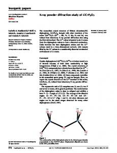
Coupled to the TRXRD information, the temperature evolution of the sample surface during the combustion front passage through the whole sample has been recorded by the infrared camera. Due to the aluminum melting, the sample emissivity evolved during the SHS reaction. Thus, this kind of camera could not adapt this change of emissivity and it has involved an incertitude on the measured temperature values. Consequently, we are not able to precisely determine neither the combustion front propagation rate, nor the maximal heating rate from the ignition to the combustion temperature. Nevertheless, it has been possible to distinguish two successive waves: first, aluminum fusion propagates from the heated end to the other throughout the sample and a corresponding wave (about 660°C) may be seen and recorded ; following it, a second wave (about 1000-1500°C) indicates that the reaction of formation takes place. The X-ray diffraction pattern presented in Fig. 5 confirms the presence of the only NbA13 phase. Thus, it can be concluded that the passage of the combustion front leads to the very fast formation of a uniform NbA13 phase.
Figure 5 : X-ray diffraction pattern of the mechanically activated self-propagating high-temperature synthesis end-product. Labeled peaks correspond to MAI3
4.3 Study of disilicides phase formation (temporal resolution of 33ms)
The X-ray fast detector which has an angular aperture of 30" 28 was centered at 3 8 O for X=0.1542 nm. This configuration could allow Si (1 1l), Mo (1 10) and Si (220) reactant peaks to be collected as well as a-MoSiz (101), (1IO), (103) and (112) reflection lines after combustion synthesis. In time resolved mode, the acquisition time for each diffractogram can be adjusted to a proper value in correlation with chemical rate of the process. 0.033 second were chosen for MoSiz formation. The TRXRD experiments coupled to the infrared imaging system allows the study of fast phase transformation study during the formation of a-MoSi2(Fig. 6). No intermediate phase was observed using a temporal resolution of 0.033s. Based on kinematic approach and quenched sample observation, the reaction of molybdenum disilicide formation takes place between liquid silicon and molybdenum nanometric' crystallites inside a powder grains. Therefore, the formation reaction of a-MoSi2 inside the moving front is Mo ,O,. + Si liq. -> MoSizsol. Combustion front velocity and maximal thermal gradient are modified by the mechanically activated state of the initial powder. Compare to classical value of SHS process in Mo-Si system [15], the .mechanical activation can multiply by a factor of three the combustion front velocity. Indeed, in this system, time resolved experiments have revealed that a-MoSiz formation by MASHS process is an heterogeneous reaction involving solid Mo and liquid Si. These kinetic results are in agreement with the KhaikinMerzhanov-Aldushin mode1 1181 and, consequently, the chemical reaction controls the combustion front velocity.
RX 99
PrlO- 97
2 theta (1=0.1542)
Nota
: Rx=(I/Io)x où x = Mo or MoSi, and 1= intensité max XRD
4.5
4.7
4.9
5.1
5.3
5.5
5.7
5.9
6.1
6.3
6.5
time ( 5 )
Figure 6 :Time Resolved XRD patterns and Infrared thermograms during the propagation of the combustion front in Mo+2Si G5(250/250/4h) sample - acquisition time for 1 diffractogram = 0.033 s and for 1 IR image = 0.066 s - h= 0.152 nm Rx = Ix / (Io x) x= Mo or MoSi2 and 1, corresponds to the maximal peak intensity recorded during time resolved X-ray diffraction expenments - Io, initial intensiîy of the peak before reaction (x=Mo) or after reaction (x= MoSi,).
In order to determine the a-MoSi2 fine microstructure, XRD profile investigations were camed out on (~*/(d*'), the slope samples obtained after MASHS process. From Langford plot [19], (d*/~*)~versus gives the mean apparent crystallites size and the y intercept of the straight line, the microstrains. Two examples of typical Langford plots are presented respectively for Mo+2Si G5(350/250/lh) and G5(350/250/3h) bal1 milling conditions in Figure 7. In addition the Langford plot for Turbula mixture (classical SHS) is reported as a reference to compare end products microstructure.
2.0OE-05
66 n m
-
350/250/3h / .-A /
160E-05 --
.4
..'
:. .."
1.20E-05 -' '
8 00E-06
-
4.00E-06
--
O
,."
/
/
/
/
/
/ Tvrbula M
3h
*
SHS
1 6 0 nm
O 005
0.01
0015
O 02
(P'I~')~
Figure 7 : End-product microstmcture : Langford plots for « bulk» molybdenum disilicide obtained from classical SHS (turbula) and MASHS {ball-milling conditions G5(350/250/lh) and G5(350/250/3h)}.
PrlO- 98
JOURNAL DE PHYSIQUE IV
As shown by the Langford plots for the three samples, ~ * / ( d * ~ linearly ) increases with ( d * / ~ * for ) ~ al1 reflection lines. From a least squares fit, the slope of the straight line gives the mean apparent crystallites equal to 66 nrn for G5(350/250/3h), 85 nm for G5(350/250/lh) and 160 nm for classical size (eMosi2) SHS. From the y intercept, the microstrains rate is evaluated within IO-^ to l u 8 for the three conditions. The values of microstrains calculated from Langford plots are nearly negligible and this observation can be reported whatever the (hkl) directions studied. End product characterization was performed using mainly XRD measurements and led to conclude that MASHS process is a suitable technique to elaborate pure nanometric a-MoSi2