streams the data to the other ECU over an optical link using the ... link and movies stored on a hard disk in the vehicle can be consid- ered. Movies and other ...
In-vehicle Movie Streaming Using an Embedded System with MOST Interface Jurgen Schoeters, Jan Van Winkel, Toon Goedem´e and Jan Meel Research Group Embedded System Design (EmSD) De Nayer Instituut, Belgium {Jurgen.Schoeters, Jan.VanWinkel, Toon.Goedeme, Jan.Meel}@denayer.wenk.be
Keywords: Infotainment, Embedded, MOST.
Abstract This paper discusses the design and implementation of an in-car infotainment system, which uses the MOST field bus as a backbone. The infotainment system is build around two ECU’s (Embedded Computing Units) for which we used Xilinx FPGA’s with integrated processor cores. An automotive camera and two other movie sources are connected with SPI interfaces to one ECU which streams the data to the other ECU over an optical link using the MOST protocol. As movie sources, a live stream from a satellite link and movies stored on a hard disk in the vehicle can be considered. Movies and other visual information are displayed on a 7 inch VGA TFT screen, integrated into the dashboard.
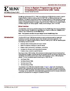
Figure 1: Infotainment system overview hardware.
1 Introduction Nowadays, consumers are demanding a wide range of multimedia features such as audio, video, voice-control and navigation in a vehicle. This demand is expected to grow and will be one of the major automotive growth areas in the future [6]. Not only the number of infotainment devices will increase, but also the need of interaction between those devices. This will seriously increase the wiring complexity, and therefore also the overall weight of the car and electromagnetical interference problems. A possible solution to tackle these problems is the MOST (Media Oriented Systems Transport) field bus. It’s fibre optic based network provides the infrastructure for exchanging high-speed audio, video, data and control information between infotainment devices within a car. The use of fibre optic interconnections reduces the overall weight of the car, increases the immunity for electromagnetic interference and reduces the wiring complexity by using a ring topology. In this paper we will discuss our experiences with the development of an infotainment system, which uses MOST as a backbone. The infotainment system is build around two embedded computing units (ECU’s), as shown in figure 1, and has multiple input sources and a 7 inch TFT screen as output. This work is related to the work of Hale et al. [3], who developed a demonstrator for the CAN bus on programmable
The remainder of this paper is organised as follows. Section 2 will give some background information about the MOST field bus. In section 3 we will discuss our experiences with the development of a MOST network interface controller, a VGA driver and SPI interfaces, and the integration of these components into a functional in-car infotainment system. Our results are discussed in section 4 and we end with a conclusion in section 5.
2 Media Oriented Systems Transport The MOST (Media Oriented Systems Transport) masterslave field bus is a functional specification defining all seven layers of the ISO/OSI reference model for data communication [5]. This functional specification is developed by an industry-standards body called the MOST Cooperation. The Cooperation was founded in 1998 by BMW, DaimlerChrysler, Harman/Becker and OASIS SiliconSystems1 . Today 15 international car makers and more than 65 key component suppliers are working with the MOST Technology and contributing towards its innovation. The MOST network may include up to 64 devices or nodes and often employs a ring topology using POF (Plastic Optical Fibre) as shown in figure 2. Other topologies such as star configurations and double rings for critical applications are 1
OASIS SiliconSystems was acquired by SMSC in March 2005
2.1 Application level
possible.
On the application level, a MOST device contains multiple components, which are called function blocks, e.g. tuner, amplifier or CD player. It is possible that there are multiple function blocks in a single MOST device, such as a tuner and an amplifier combined in one case and connected to the MOST network via a common MOST Network Interface Controller. There are three types of different function blocks: • Slaves, function blocks that are always controlled. • Controllers, function blocks that control other function blocks. • Human Machine Interfaces, function blocks that have an interface to the user. Figure 2: MOST ring MOST allows simultaneous transmission of multiple data streams such as control, packet and real-time information using synchronous and asynchronous data channels. The synchronous channels provide guaranteed bandwidth, and allow a maximum data throughput of 25 Mbit/s or 50 Mbit/s, although higher speed grades (150 Mbits/s) are upcoming. The bandwidth of the asynchronous data channels is limited to 15Mbit/s (30Mbit/s). There is a dedicated channel for asynchronous control data with a guaranteed data throughput of 700 Kbit/s (1400 Kbit/s). Easy object oriented application development is possible because MOST defines all layers of the ISO/OSI model. These layers are also recognisable in the general representation of a MOST device as shown in figure 3 .
Each function block contains a number of simple functions. For example, a DVD player possesses functions such as Play, Stop, Eject and Time Played. A function is addressed independently of the device it is in. In addition to the device specific function blocks, which represent applications, each MOST device has a special function block called the NetBlock. The NetBlock provides functions related to the entire device.
2.2 Network service layer The network service layer is an abstraction layer between the function blocks and the MOST network interface controller. Many functions are preformed by the network service layer such as address translation, network control, construction of messages, channel allocation, . . . The address translation is used if the address of the requested function block is not known. The network service layer will first look for the address in a local table if it is not present the network master will be consulted. The network master has knowledge of all present devices and its function blocks. Other tasks of the network service layer are to monitor the network control messages from the master and act accordingly, construct control and asynchronous messages and allocate a channel for a synchronous data stream.
2.3 MOST Network Interface Controller
Figure 3: General representation of a MOST device and ISO/OSI representation The following sections will discuss these layers more thoroughly, starting with the application layer in section 2.1 and working down to the physical layer. Section 2.2 will discuss the presentation, session, transport and network layer which are grouped in a MOST device as the Network Service layer. The MOST Network Interface Controller, data link layer in the ISO/OSI model, is discussed in section 2.3. And finally the physical layer is discussed in section 2.4.
Data transfers over MOST are organised in blocks of frames. A block consists of 16 frames with 64 bytes each as shown in figure 4. Per frame, 60 bytes of data are available for synchronous and asynchronous packet data, while two bytes transport control data. The remaining two bytes are used for frame control and consist out of a 4-bit preamble, a parity bit, some control bits and a 4-bit boundary descriptor. The boundary descriptor controls the bandwidth for synchronous and asynchronous data transmission. It represents the number of 4 byte blocks (quadlets) of data used for synchronous data, with a minimum value of 6 and a maximum value of 15. Note that this results
Figure 4: Overview of a MOST block and frame in a maximum of 36 asynchronous data bytes per frame.
2.4 Physical Interface The most commonly used transport medium in a MOST network is POF (Plastic Optical Fibre). The 50 Mbit/s specification introduced a special signal processing technology known as ePHY, which enabled MOST communication over shielded or unshielded copper cables, in addition to POF. This additional transport medium was introduced on request of certain car manufacturers such as Toyota . . . .
disk and satellite modem are provided by Agilent Technologies and are used as movie sources. Orban Microwave Products delivers an antenna for the satellite modem. All this components will be brought together into a modified Mercedes E-class dashboard provided by Recticel. De Nayer Instituut is responsible for the development of a MOST HMI (Human Machine Interface) node using a 7 inch TFT VGA screen which will be integrated into the dashboard by Recticel. Furthermore, De Nayer Instituut provides a MOST slave node which interconnects the camera, hard disk and satellite modem to the MOST field bus. Figure 5 gives a global overview of the infotainment system.
The physical layer consists out of a FOT (Fibre Optical Transceiver) or ePHY transceiver, depending on the selected transport medium, and a Manchester modulator/demodulator.
Section 3.1 will discuss the development platform we used. Where section 3.2 will discuss the development of a MOST HMI node and section 3.3 the development of a MOST slave node.
The POF used in the 25 and 50 Mbit/s specifications is not sufficient enough [4] for the upcoming 150 Mbit/s specification due their high fibre attenuation, thermal sensitivity and the limited bandwidth. A solution for this problems is largecore low-loss polymer-cladded silica (PCS) fibre.
3.1 Development platform
3 Infotainment System We developed an in-car infotainment demonstrator. The goal of the demonstrator is to gain experience in the integration of several in-car multimedia devices into an infotainment system, with a common technology as a backbone (MOST). This will result in a smaller BOM (Bill Of Materials) and will influence cost and overall weight of the car in a positive manner. The development of the infotainment system is a cooperation between De Nayer Instituut, Melexis, Agilent Technologies, Orban Microwave Products and Recticel, and is guided by an organisation called Flanders’ DRIVE. The goal of Flanders’ DRIVE is to stimulate automotive innovation in Flanders. Melexis provides the MOST physical interface (Fibre Optic Transceivers and fibres) and an automotive camera. A hard
The MOST nodes are implemented on XUP (Xilinx University Program) Virtex-II Pro development boards. Each board contains a XC2VP30-7C Virtex-II Pro FPGA which has two integrated Power PC processor cores, 306 KB of internal RAM and 13696 slices. Further, the development board contains the following features: • • • • • • • • • •
DDR RAM slot Compact Flash slot 10/100 Ethernet PHY device RS-232 DB9 serial port Two PS-2 serial ports Five push buttons 120 extension I/O pins VGA output AC-97 audio codec Three SATA ports
Figure 5: Hardware (left) and software (right) overview of the infotainment system Out of this resources we used the VGA output, Compact Flash slot, DDR RAM slot and expansion IO for the working infotainment system. The DDR RAM slot is equipped with a 512 MB DDR RAM module.
Section 3.2.1 describes the development of the VGA driver and section 3.2.2 handles on the development of the MOST transceiver. 3.2.1 VGA display driver
3.2 MOST HMI node
Figure 6: Screenshot with OSD menu The MOST HMI node contains a self-made hardware VGA display driver and MOST transceiver, and additionally includes IP cores to realise internal communication between the different hardware building blocks. One processor core inside the FPGA runs on Linux, and realises the HMI (Human Machine Interface), the movie playback and the communication between the different hardware building blocks. As Linux is open source, it enables the development of custom device drivers [1][2] and other programs. For the MOST HMI node device drivers are written to interface with the MOST transceiver, the VGA display driver and some input buttons. Movie playback is accomplished using the open source movie player MPlayer, which is efficient with hardware resources and has on-screen display (OSD) capabilities. The on-screen display consists of an image superimposed on the movie that shows a menu and allows the user to select another movie source or camera stream by pressing a specific button. A screenshot of this graphical OSD menu is shown in figure 6.
The hardware VGA display driver provides the VGA timing for a 7 inch TFT screen with a resolution of 640x480. This is the minimal resolution of the TFT screen, but this resolution is too high to process the movie with a software movie player on the limited Power PC processor core inside the FPGA. To solve this problem, only movies with a resolution of 320x240 or less are used. As earlier mentioned, the TFT screen only supports resolution as low as 640x480, so the lower software resolution of 320x240 must be scaled to 640x480 in hardware. This scaling is implemented by repeating each pixel and line of the frame buffer. Each original pixel is copied, resulting in a square of four identical pixels. This rudimentary resolution upscaling is implemented very efficiently in hardware. This operation is shown in figure 7. The frame buffer of the VGA driver is placed in a DDR-memory module on the development board. This is done because the FPGA has only 306 KB of internal memory and 307,2 KB (320x240 * 4 bytes) is needed to hold the frame buffer.
Figure 7: Original 3x1 image (left) and scaled 6x2 image (right)
3.2.2 MOST transceiver We developed a MOST transceiver which supports framing and deframing of MOST frames as described in the MOST Network Interface Controller (data link layer) and Physical Interface (physical layer) specifications. Unfortunately, we were not able to reach full compliance with the specification because the public available specifications [5] do not define all necessary fields e.g. the preamble, frame control and status bits field, . . .
The MOST frames are transmitted over the medium (POF) using Manchester coding. This allows clock and frame recovery by means of a PLL (Phase Locked Loop) on the receiving side, in our design we made use of oversampling instead of a PLL to correctly receive the frames. Due to the use of oversampling and the maximum clock frequency of the FPGA our implementation can only support MOST with a bitrate of 25 Mbit/s. The bitrate of 25 Mbit/s yields a symbol rate of 50 MSymbols/s for Manchester coding. To recover the symbol correctly an oversampling rate of at least 4 times is needed. Therefore a clock rate of 200 MHz is necessary to support MOST with a bitrate of 25Mbit/s, for a MOST bitrate of 50Mbit/s we would need a clock of 400 MHz which is not supported by the Virtex-II Pro FPGA.
The resources needed to play the movie stream on the MOST HMI node depend on the presence of an OSD menu. The CPU utilisation is around 60% when the OSD menus are present and a bit less when not (45-50%). The memory footprint for Linux on the MOST HMI node is around 13 MB. Used hardware resources: • MOST HMI node: 71% of the available FPGA slices and 51% internal memory • MOST Slave node: 53% of the available FPGA slices and 86% internal memory
The design supports on-the-fly changes of the boundary descriptor values and transmission of synchronous, asynchronous and control data simultaneously. On the receiving side, the design will split the synchronous and asynchronous data accordingly the boundary descriptor value, and the control data into separate data streams.
3.3 MOST slave node The MOST slave node contains a self-made MOST transceiver, as discussed in section 3.2.2, and SPI master interfaces to interface with the camera, hard disk and satellite modem. Our design uses both processor cores of the Virtex-II Pro FPGA. One processor core, the command processor, processes the control messages of the MOST frames and the other processor core (the source processor) transfers the data from a selected SPI interface to the MOST transceiver. This is shown from a software point of view in figure 5. User actions on the MOST HMI node influence the the control messages received by the command processor core. The user can select another movie source using the OSD menu, this selection will be translated by the MOST HMI node into a specific control message. On the receiving side the command processor will issue a command to the source processor to select the correct SPI interface as input source. The command issuing between the processors is done by using a shared memory that can be accessed and monitored by both processors. Other commands from the MOST HMI node, by example selecting a movie or retrieving the list of available movies on the hard disk, are passed to the command SPI interface. If the command processor transmits a request for updating the movie list over the SPI interface it will wait for a response, and transmit this response to the MOST HMI node.
4 Results The result of our development is a working infotainment system which uses MOST to stream the data generated by the movie sources from one node to another. Movie streams up to 25 Mbit/s are supported.
Figure 8: The demonstrator Figure 8 shows a picture of our demonstrator. Notice the optical ring interconnecting the two development boards and the 7 inch display.
5 Conclusion This paper discussed the development of an in-car infotainment demonstration system. The result of the development is a working infotainment system for streaming movies over a MOST network. Only the 2 lowest layers of the MOST specification are implemented because these where enough to support the movie streaming. Those layers are the physical interface and MOST Network Interface Controller layer. Full compliance with the specifications was not possible because some parts of the MOST frame where not defined in de public available specification [5]. The developed infotainment system exists out of 2 nodes: a MOST HMI node and a Slave Node. Input sources are connected to the slave node using an SPI interface and selected with commands from the HMI node which is responsible for movie playback and interaction with the user. Each node is implemented in a XUP Virtex-II Pro development board which contains a Virtex-II Pro FPGA with internal Power PC processor cores. Linux is chosen as operating system for the HMI node with MPlayer as movie player. The open source nature of Linux has the advantage of easy device driver and program development. Multiple device drivers where written to interface with the
self-written VGA driver, most transceiver and IP cores. The slave node hardware exist out of 3 SPI masters, a MOST transceiver and IP cores. The software on the slave node is a standalone dual core program.
Acknowledgments The authors greatly acknowledge the financial support of Flanders’ DRIVE, the innovation platform for the Flemish vehicle industry funded by the IWT (www.iwt.be), and the partners in the MultiCarCom project: Melexis, Agilent Technologies, Orban Microwave Products and Recticel.
References [1] D. P. Bovet and M. Cesati. Understanding the Linux Kernel. O’Reilly Media, second edition, December 2003. [2] J. Corbet, A. Rubini, and G. KroahHartman. Linux Device Drivers. O’Reilly Media, third edition, February 2005. [3] K. Hale. Automotive databus simulation using vhdl. In EURO-DAC ’94: Proceedings of the conference on European design automation, pages 592–597, Los Alamitos, CA, USA, 1994. IEEE Computer Society Press. [4] T. Kibler, S. Poferl, G. B¨ock, H.-P. Huber, and E. Zeeb. Optical data buses for automotive applications. IEEE Journal of ligthwave technology, 22(9), September 2004. [5] MOST Cooperation. MOST Specification, 2.4 edition, May 2005. [6] C. Webber. Infotainment semiconductor demand. Automotive multimedia & communications service report, Strategy Analytics, December 2006.