Incorporating Cooperative Portlets in Web Application Development. Nathalie Moreno, José Raúl Romero and Antonio Vallecillo. Dpto. de Lenguajes y Ciencias ...
Incorporating Cooperative Portlets in Web Application Development Nathalie Moreno, Jos´e Ra´ul Romero and Antonio Vallecillo Dpto. de Lenguajes y Ciencias de la Computaci´on Universidad de M´alaga, Spain {vergara,jrromero,av}@lcc.uma.es
Abstract Portlets-based software development is gaining recognition as a key technology for the construction of robust and evolvable Web applications. Emerging portlet standards like JSR-168 or WSRP—along with commercial development tools and portal servers—enable designers to quickly develop, integrate and run “composite” Web portals, which integrate specific platforms and partners. Despite this significant progress, there is a lack of guidelines and models for addressing the development of portlet-based Web applications from a technology-independent viewpoint. This work tries to identify the main concerns involved in modeling portlets, determine the major models required to capture these concerns, and propose a way to address their integration into Web applications, from a platformindependent point of view. In so doing, we also introduce mechanisms for modeling inter-portlet communication and cooperation capabilities independently of the target portal server product.
1. Introduction A current tend in the development of distributed Web applications is to reuse and assemble pre-produced components—such as Web services or portlets—for reducing development costs and improving software quality. The assembly of these third party systems for building Web applications has been successfully applied in practice. In fact, Web services are commonly used as the main building blocks for generating Web applications and portals. One of the limitations of Web services is that they focus on the service functionality, but without dealing with presentation issues. This forces the re-creation of the presentation layer in each client application that uses the Web service. Besides, the corporative image and many of the marketing aspects of the service are lost if presentation is not considered, something which is very important for some service providers (their brand name is a key factor
for their business—think for instance for Adobe, IBM, or Coca-Cola, whose corporate image and logo are crucial for selling their products and services). To overcome this limitation, portlets provide integration in both the business logic and the presentation layer allowing end-users to interact directly with the service. From an application perspective, a portlet is an individual Web-based component that typically handles requests and generates only a dynamic fragment of the total markup that a user sees from his or her browser [3]. The content of a portlet is normally aggregated with the content of other portlets to form the final portal page. That is the reason why portlets are rarely run in an isolated way, but together with other portlets. However, when a user navigates within one portlet, the others usually remain unchanged ignoring what is being rendered by it. In order to transfer data from one portlet to another, users have to manually copy and paste key data from sources to targets portlets. This means that each portlet has to be searched individually for relevant information. The need for effectively modeling, integrating, communicating and sharing data among cooperative portlets has been addressed by many portal servers (Oracle, IBM, BEA, etc). They provide proprietary extensions to industry portlets standards such as the Web Services for Remote Portlets (WSRP) specification by OASIS [13], or the JSR168 development model proposed by JCP [6]. However, these extensions are: (i) not portable to other servers, (ii) often require the use of concrete development tools closely tied to a particular platform technology and architectural style (e.g., the WebSphere Portal tool only supports the MVC design) and, (iii) implement a simplified means of data sharing among portlets. As a consequence, there is current a lack of guidelines and modeling concepts to address the portlets-based portal development from a technologyindependent viewpoint. Web Engineering proposals have traditionally aided the industry Web software development to further improve its productivity, quality and longevity. Although the majority of those proposals provide excellent methodologies and
tools for the design and development of Web applications, the study of integrating Web applications within cooperative third party systems (such as Web services, portlets or legacy systems) has been particularly overlooked until recently. It is very likely to be introduced in future extensions, but currently there is current a lack of guidelines about how portlets should be modeled, how they should be integrated in a Web application or how inter-portlet communication capabilities should be offered. In this paper we try to identify the main concerns involved in modeling portlets and determine the major models required to capture these concerns (see Section 2). Using the travel agency example, Section 3 proposes a strategy for modeling portlets and their integration into Web applications from a platform-independent viewpoint. In so doing, we introduce also mechanisms for modeling interportlet communication and cooperation capabilities independently of the target portal server product. Finally, Section 4 sketches some conclusions and outlines some further research activities.
2. Reference Models for Portlets Broadly speaking, the main difference between a Web application and a portlet stems from the fact that the former is an aggregate of pages whereas the latter is an aggregate of fragments. Apart from that, both the Web application design and the portlet design share many features and concerns. Based on their similarities, we will make use of the general framework presented in [11, 12] for describing Web applications in order to identify the major required models involved in the modeling of portlets1 . Next subsections look at framework viewpoints briefly and describe the concepts and models that rise up during the portlet-based applications construction. How to use them for addressing portlet specific requirements will be discussed in Section 3.
2.1 The User Interface Viewpoint Typically, portlets are considered as user-facing applications which offer more than just content display to their users. They also allow them to interact with the content by means of forms, entry data fields, radio buttons, check boxes, etc. The User interface viewpoint is directly concerned with how the client interacts with the portlet and how information is structured for providing a user-friendly interface through a coherent look and feel of its visual elements. 1 That framework was specifically designed to integrate third party applications and legacy systems into Web systems by separating independent concerns into a set of views on the system, each one addressing one particular viewpoint (user interface, business logic, persistent data, distribution, etc)
User Interface User
Presentation
Conceptual Model Adaptation
Context
Navigation
Business Logic
Processes
Structure
Internal Processes Component + Architectural style
Choreography
Distribution
Data
Information Structure
Information Distribution
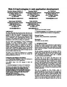
Figure 1. Reference models for portlets
This viewpoint consists of six main models: Conceptual, Navigation, Presentation, User, Context and Adaptation (see Figure 1). For modeling an individual portlet we need at least its Conceptual, Presentation, and Navigation models at the User Interface level. In case of adaptation requirements, the others could be needed, too. Generally, all these models are not usually supplied from the portlet providers; rather, they need to be built from the portlet information (which, by the way, tends to be imprecise, scarce, and insufficient). In any case, they are required for any model-driven development approach. − The Conceptual model encapsulates the information handled by the rest of the models at the User Interface level. Since each user looks at the same information and navigates through the application in a different way, different views of this model can be defined. UserInformationUnits, Attributes and Associations comprise the major elements of this representation. − The Navigation model describes the application navigational requirements building the navigational structure of the final application—a portlet in this case. This implies expressing how users can visit a collection of related data in a non-linear way. To this end, NavigationUnits, NavigationLinks2 , Events and AccesStruc2 Not
to be confused with UML “links”. NavigationLinks represent as-
tures have been defining among other concepts for representing the logic of this model.
the portlet, taking into account the tasks that users can perform.
− The Presentation model captures the presentational requirements in a set of PresentationUnits (text, image, pages, sections, forms, etc.) and Transitions, which sketch aesthetic aspects and the look&feel of the portlet.
− The Internal Processes model specifies the precise behavior of every BusinessProcessInformation or component as well as the set of activities that are executed in order to achieve a business objective.
− The User model describes and manages the user characteristics [5, 4] with the purpose of adapting the content and the presentation of information to their needs and preferences. Generally, the User model is expressed in terms of the following concepts: User, UserFeature, Role, Preference, PreviousKnowledge, History and Session. − The Context model. Following [7], context is defined as the reification of certain properties, describing the environment of the application and some aspects of the application itself which are necessary to determine the need for customization. Context deals with Device, Network, Location and Time aspects. − The Adaptation model is performed based on user’s knowledge, preferences or context features to obtain appropriate Web content characteristics and target markup for each device Generally, the Adaptation Model is expressed as a set of mathematical expressions or ECA rules associated with navigation and presentation concepts in adaptation models [5, 4, 9].
2.2 The Business Logic Viewpoint This level describes the behaviour of the portlet, independently of its user interface, and the persistent data it handles. To provide detailed descriptions to perform business processes, actions, events handling and errors management is delivered to this viewpoint. From our point of view, modeling the behaviour of a portlet can be done using the following five models (see Figure 1): Structure, Internal Processes, Choreography, Distribution and Architectural Style. Among them, the models that comprise the description of the portlet are: the structure, internal processes, and choreography models. − The Structure model describes the major classes or component types representing services in the system (BusinessProcessInformation), their attributes (Attributes), the signature of their operations (Signature), and the relationships between them (Association). The design of the Structure model is driven by the needs of the processes that implement the business logic of sociations in the Navigation model, whereas UML links are just instances of UML associations.
− The Choreography model defines the valid sequences of messages and interactions that the portlet may exchange [17]. The choreography may be externally oriented, specifying the contract a component will have with other components (PartialChoreography) or, it may be internally oriented, specifying the flow of messages within a composition (GlobalChoreography). − The Distribution model describes how functionality is distributed in Nodes, connected by means of point to point connections or Links. Nodes can be static, dynamic or mobile. StaticNodes represent Devices, Places or Actors of the system. Dynamic nodes model points of computing (ComputingNode) where Activities are performed. Both StaticNodes and ComputingNodes may be MobileNodes for relevant issues of a mobile System, concerning the mobility of both physical (e.g. computing nodes) and logical entities (e.g. software components). The global view of Nodes and Links comprises a Network. − The Architectural Style model deals with how functionality is encapsulated into business components and services. Each Architectural Style has different associated entities depending on the pattern applied which makes the distinction between different architectural styles. For portlets development, the MVC style is the most used. It defines: (i) a Model that is responsible for storing the state and the application logic; (ii) Views that provide the user of the application with a presentation of the current state of the application; and (iii) a Controller that is responsible for mapping user interface events to calls that invoke operations on the model. That is, the glue that ties the model to the view and defines the interaction pattern in the portlet.
2.3 The Data Viewpoint Although portlets cannot be considered as data-centric applications, they require high-performance infrastructure for data storing. Information is needed not only for portlet consumers but also for its processes. This level describes the information handled by the application and provides a mechanism for managing and storing data persistently. This viewpoint is organized around two models: the Information Structure and the Location models.
− The Information Structure model deals with the information that has to make persistent in terms of InformationUnits, Attributes, Relationships, Constraints and AccessOperations. − The Location model describes the distribution and replication of the data being modelled, since information can be fragmented in Nodes or replicated in different Locations. These models are not relevant in our case, because we are concerned on how to interact with the portlet, not how it internally stores its persistent data. For a more detailed description of these viewpoints and the semantic of their associated models and concepts, the interested reader can refer to [11].
2.4 Dependencies between Models Although the models of the framework are ideally independent of each other, some of them capture requirements on the same element of design (e.g., events, properties or actions). Therefore some modifications in a model can affect other models. We add precision to model elements and the relationships among them by means of unambiguous OCL constraints (preconditions, invariants and postconditions). For example, Figure 1 shows a connection between Presentation and Structure Business models. In this way, Transitions in the Presentation model consists of Events which model a significant occurrence located in time and space. These Events have to be also Events in the context of Internal Processes models, which trigger the execution of an associated behaviour. This can be formally expressed as an OCL constraint. Interdependencies determine not only the methodological guidelines to be followed, but also something more important: they establish how the different viewpoints merge and complement each other.
Our proposal is aligned with the MDA framework [16, 1, 10] and particularizes general guidelines presented in previous work [11, 12]. To be precise, the development of portlets-based Web applications in the MDA context is based on the following steps: Step 1 Create the class diagrams (PIMs) describing models for each Web application layer. In this step, we identify the global systems requirements at three levels of abstraction: User Interface, Business Logic and Data levels. As a result of this phase, three PIMs are generated describing high-composition architectural views of the services and components of our application. Step 2 Mark the PIM elements with stereotypes identifying the system scope and boundaries, i.e, the data and services that will be provided by our system, and the ones that will be externally required. At this point, we will describe how portlets cooperate (portlet aggregation [2]) with each other to produce and achieve the global functionality that the system is required to implement—either by sending signals or invoking operations. Step 3 Specify the target platform. We need to determine the concrete platforms and communication mechanisms between our application and the external systems identified previously. Step 4 Generate the PSMs. Step 5 Generate the code (e.g., the Web pages). Integration and cooperation among portlets can be carried out at two levels of abstractions: at the user interface level and at business logic level. In following subsections we are going to focus on these two viewpoints proposing a strategy for addressing both issues through the travel agency system (TAS) example (see http://www.lcc.uma. es/˜av/mdwe2005/TheTASexample/ for a complete description of this scenario).
3. Designing Portlet-based Web Applications 3.1. Addressing the User Interface Level The design of a portlet-based Web application can be addressed combining existing models of individual portlets with additional models describing the extra-functionality supported by our Web application. Following this strategy, the design process is strongly governed by the (too early) implementation decision of using portlets and, consequently, if we want to reuse another type of component technology or provider in the future, we are forced to redefine all the Web application models from the beginning. On the contrary, we have opted for delaying as much as possible implementation decisions, in order to obtain a set of reusable platform-independent models.
At first sight, it could be considered that the role of the main system for portlet-based Web applications is limited to a customizable facade providing a single sign-on service for assembled portlets. However, the unique rendering space of a portal adds complexity to the application model when we consider multiple portlets co-existing on a Web page. As mentioned in the introduction, when a user navigates within one portlet the others usually remain unchanged, ignoring what is being rendered by it. In order to transfer data from one portlet to another, users have to manually copy and paste key data from sources to targets portlets. We will try
to model inter-portlet data dependencies—at user interface level—to free users from this task.
TravelAgency
Air_Line Flight Customer
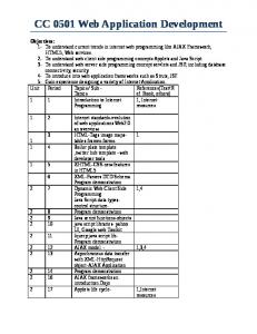
3.1.1 The Conceptual Model To design the PIM of this viewpoint, we need to identify— in the first place—the information that will be presented to the user during a session . These requirements are captured in the Conceptual model. That model for the TAS example is shown in Figure 2. However, we need to decide how to deal with this model when we want to re-use particular portlets such as Iberia, Bancohotel or PepeCar which have their own non-public Conceptual Models. In many cases, these portlets will place additional constraints—as well as specialized collaborations and data exchange—that can not be modelled in a typical UML class diagram. TravelAgency +description +name request_for
Customer +creditcardnumber +creditcardtype +email +expiredate +idcustomer +login +name +password
1
0..*
books 1..*
Car_Hire +description +logo +name
HolidayPackage +date +description +idpackage +price
provides
0..* Flight
1..*
+idflight +arrival_city +arrival_date +departure_city +departure_date +seat_class +seat_number +seat_row
Booking +description +idbooking +price
Car +car_reg_number +car_type +city +end_date +start_date
0..* Room provides Air_Line +description +logo +name
+city +end_date +idroom +room_type +start_date ...
Hotel +city 0..* provides +description +logo +name
Figure 2. Conceptual model for the TAS
Therefore, we need to particularize and model the ability by which specific class instances (specific portlet implementations) will match the system requirements and will communicate/share data with each other. In this regard, UML 2.0 [15, 14] introduces a new structural diagram called Composite Structure diagram. A Composite Structure diagram “depicts the internal structure of a classifier, including the interaction points of the classifier to other parts of the system. It shows the configuration of parts that jointly perform the behavior of the containing classifier. The architecture diagram specifies a set of instances playing parts (roles), as well as their required relationships given in a particular context.” Consequently, starting from Figure 2 we are going to derive a Composite Structure Conceptual Model, as a set of
+creditcardnumber +creditcardtype +email +expiredate +idcustomer +login +name +password
book
Hotel Room
HolidayPackage +date +description +idpackage +price 1..* Booking +description +idbooking +price
Car_Hire Car
Figure 3. Composite conceptual model
parts interacting together to achieve user interface requirements. Since Airline, Hotel and CarHire classes are only used in the navigational context of the TravelAgency class, we model this fact considering them as parts/properties of the containing class TravelAgency. Likewise, the Flight, Room and Car classes form part of the Airline, Hotel and CarHire data structures respectively. Thus, Figure 3 represents the fact that when an instance of the TravelAgency is created, a set of instances corresponding to its properties (one Airline, Hotel and CarHire instances) are created as well—either immediately or at some later time. Each part or property is isolated from its environment by means of a port, which will drive the interactions with its environment3 . On the other hand, connectors define channels along which messages are sent. Thus, when a costumer makes any request to the portal, the request is captured by the TravelAgency port, which delegates it to the appropriate portlet on the portal page. Although this model works well at the Conceptual level, it is incomplete because it does not reflect the internal collaborations between the TravelAgency, AirLine, Hotel and Car classes. Rather, it models a travel agency system from a global point of view. Moreover, if we want to model how a data item is shared (or broadcasted) from one portlet to multiple target portlets in the page, we need to define a “collaboration”. A UML collaboration is a selective view of that situation. It may be attached to an operation or a classifier through a CollaborationOcurrence. Such a collaboration can constrain the set of valid interactions that may occur between the instances that are connected by a link. Furthermore, a collaboration specifies the property instances that can participate in the collaboration. For example, consider Iberia, Bancotel and PepeCar, three portlets on the same application screen. It would be interesting to retrieve and use the arrival City from the row in the summary Iberia portlet listing as an entry value for the 3 As we shall see, ports will represent portlets containers at implementation level for the Airline, Hotel and CarHire classes.
City textbox of the Bancotel portlet. Then, the page would
present the list of hotel offers to the customer. In this way, both portlets now would display related information, while the third portlet still shows their entry panel (Figure 4 illustrates this collaboration). Air_Line
Hotel
Flight +arrival_city +arrival_date
Room server
Filler
client
...
+city +start_date ...
Client.city Client.start_date
= Server.arrival_city = Server.arrival_date
Figure 4. Collaboration diagram for the TAS
As an aside, please note that although inter-portlet communication can be modeled using any of the aforementioned methods (Composite Structure diagrams and collaborations), one must be careful about the dependencies that are introduced when using inter-portlet communication. In the Iberia/Bancotel portlets example, what would happen if the user decided to remove the Iberia portlet from his page? Would the Bancotel portlet still be functional? Should we force the user to remove the Bancotel portlet as well? These are some of the design considerations that need to be taken in account before using inter-portlet communication. 3.1.2 The Navigation Model At this point, the Conceptual model is complete. Then, the Navigation model is built as a refinement of the Conceptual model we have just defined. The Navigation model specifies the navigational structures of the Travel Agency, i.e., how users navigate through the available information using Indexes (¿IndexÀ HolidayPackageIndex), Menus (¿MenuÀ HolidayPackageMenu, ¿MenuÀ BookingMenu, ¿MenuÀ CustomerMenu) or Guided Tours (¿GuidedTourÀ BookingGuidedTour). We have added constraints to ¿NavigationLinksÀ describing which events will trigger the navigation through the link (e.g., when a process finishes, after clicking a ¿MenuOptionÀ, etc.) 3.1.3 The Presentation Model After that, the Presentation model further refers to groups of pages organized around ¿PresentationUnitsÀ as: (i) ¿SinglePresentationUnitsÀ, with their attributes marked as ¿textÀ, ¿imageÀ, ¿buttonÀ, etc.; and (ii) ¿GroupPresentationUnitsÀ that comprise UML classes and packages stereotyped ¿pageÀ, ¿sectionÀ or ¿formÀ. Basically, we have used in our example ¿ExternalSectionÀ to display portlet responses
and ¿pageÀ to display the main portal pages. We have also marked as ¿ExternalFormsÀ those UML classes that invoke external services. Note that each ¿ExternalPresentationUnitsÀ has information about its own data, structure, presentation, etc. Since adaptation is not required in this case, the final PIM of the User Interface viewpoint is obtained by merging these three models, and is shown in Figure 5. Once the PIM of this layer is described, we need to provide some sort of support for its deployment, configuration and execution in a particular platform, i.e., we need to generate its corresponding PSM. This last step only concerns UML packages stereotyped ¿GroupPresentationUnitsÀ, because integrated portlets deal with their corresponding ¿ExternalGroupPresentationUnitÀ. Applying a two-fold transformation process from model-to-model (based on, e.g., ATL mapping rules) and model-to-code (using, e.g., templates that contain predefined parts of the meta-code text), we can map the source PIM to a target PSM and to code finally. The feasibility of these transformations and how the Web pages are obtained from them is well documented in [8].
3.2. Addressing the Business Logic Level The same as the User Interface Viewpoint, the Business Logic view of the system needs to be platform-independent and interchangeable. Portlets typically evolve over time and are largely reused as bases for new portlets. Thus, the ability to change a portlet model or to adapt it to a new provider requires that each business logic model be self-contained and extensible. As shown in Figure 6, the PIM for this viewpoint is focused just on the system operations hiding the rest of the details (software architecture, distribution, system boundaries, communication protocols, implementation platforms, etc.). This solution is specified in terms of UML packages and their interconnections in a platform independent way, achieving reusability across different target platform environments. Thus, the PIM does not contain any information on the pieces of functionality that will be locally implemented, and the ones that will be provided by external services and applications. Once that high-level PIM is specified, we need to identify the system scope and boundaries, and then build a model of the system with this information. That target model (still a PIM, but with that information on it) will be built by transforming the original PIM using marks (see Figure 7). To identify the elements in the TAS PIM that should be transformed in a particular way, we will use the stereotypes ¿ExternalSystemÀ and ¿ExternalAssociationÀ. An ¿ExternalSystemÀ defines any other external system interacting with the system under
TravelAgency
TravelAgency Menu
ListHolidayPackages() SearchByCar() SearchByFlight() SearchByFlight_Car() SearchByFlight_Hotel() SearchByFlight_Hotel_Car() SearchByHotel() SearchByHotel_Car()
TravelAgency -description -logo -name
Customer
HolidayPackage
CustomerMenu +NewMemberRegistration() +SigIn()
HolidayPackage
HolidayPackageIndex
-date -description -idpackage -price
+SortByBestValue() +SortByDistance()
Customer -creditcardnumber -creditcardnumber -creditcardtype -email -expirydate -login -name -password ...
HolidayPackageMenu +ChangeSearch() +SelectPackage() +ViewDetails()
AirLine
Air Lines
AirLineMenu
+arrival_city +arrival_date +class +departure_city +departure_date +description +logo +name +num_person +one-way +round-trip
+Find()
Flight -idflight -arrival_city -arrival_date -departure_city -departure_date -seat_class -seat_number -seat_row -price
BookingMenu
Hotel
+BookPackage()
Hotel
HotelMenu +Find()
+city +description +end_date +hotel_class +logo +name +room_type +start_date
Room -city -end_date -hotel_id -hotel_name -idroom -price -room_type -start_date
BookingGuidedTour
CarHire
Car_HireMenu +Find()
Car_Hire +car_type +city +description +end_date +logo +name +start_date
Car -car_reg_number -car_type -city -end_date -price -start_date
Figure 5. The PIM of the User Interface viewpoint
Booking -description -idbooking -price
air_lines Air_lines +find_flight( inf_req : Fly_req ) : Fly_list +reserve_flight( fly_sel : Fly_Inf ) : Reserv +pay_flight( pay_inf : Pay_Inf ) : Ack_pay +cancel_flight( reserv_inf : Reserv ) : Ack_cancel
car_hire Car_Hire +find_car( car_req : Car_req ) : Car_list +reserve_car( car_sel : Car_Inf ) : Reserv +pay_car( pay_inf : Pay_Inf ) : Ack_pay +cancel_car( reserv_inf : Reserv ) : Ack_cancel
travel_agency
nentized”, prior to decide the technology and the service providers. This componentization will be described using the UML 2.0 constructs and infrastructure for describing software architectures, because what we want to build in this phase is the software architectural description of the system. This transformation will be guided by the following mapping rules:
Travel_AG +find_travel( travel_req : Travel_req ) : Travel_list +reserve_travel( travel_sel : Travel_Inf ) : Reserv +pay_travel( pay_inf : Pay_Inf ) : Ack_pay +cancel_travel( reserv_inf : Reserv ) : Ack_cancel
hotel Hotel +find_room( room_req : Room_req ) : Room_list +reserve_room( room_sel : Room_inf ) : Reserv +pay_room( pay_inf : Pay_Inf ) : Ack_pay +cancel_room( reserv_inf : Reserv ) : Ack_cancel
• Classes transformation. The UML class stereotyped as ¿InternalSystemÀ or ¿ExternalSystemÀ is mapped to a UML Class holding the same characteristics as its original (name, attributes and operations).
bank Bank +make_payment( pay_inf : Pay_Inf ) : Ack_pay
Figure 6. The TAS Structure PIM
consideration. In the same way, an ¿ExternalAssociationÀ defines an interaction between the system under deployment and an ¿ExternalSystemÀ [11].
air_lines
Air_lines +find_flight( inf_req : Fly_req ) : Fly_list +reserve_flight( fly_sel : Fly_Inf ) : Reserv +pay_flight( pay_inf : Pay_Inf ) : Ack_pay +cancel_flight( reserv_inf : Reserv ) : Ack_cancel
car_hire
Car_Hire
+find_car( car_req : Car_req ) : Car_list +reserve_car( car_sel : Car_Inf ) : Reserv +pay_car( pay_inf : Pay_Inf ) : Ack_pay +cancel_car( reserv_inf : Reserv ) : Ack_cancel
travel_agency
Travel_AG +find_travel( travel_req : Travel_req ) : Travel_list +reserve_travel( travel_sel : Travel_Inf ) : Reserv +pay_travel( pay_inf : Pay_Inf ) : Ack_pay +cancel_travel( reserv_inf : Reserv ) : Ack_cancel
hotel
Hotel +find_room( room_req : Room_req ) : Room_list +reserve_room( room_sel : Room_inf ) : Reserv +pay_room( pay_inf : Pay_Inf ) : Ack_pay +cancel_room( reserv_inf : Reserv ) : Ack_cancel
bank
• Packages transformation. Each UML package is mapped to a UML Component initialized with the same as its corresponding UML package.
Bank
• Associations transformation. For each UML association stereotyped ¿ExternalAssociationÀ, two component ports will be generated, each one as Association ends of that relationship. Ports will be associated to the UML Component derived in the previous step. Its behavior is defined in terms of an interface associated with that port, which specifies the nature of the interactions that may occur over that port. Thus, the port interface’s name is given the value of the UML class name from which it is derived and its operations correspond to its UML class operations. • Association’s ends transformation. For the endpoint of an ¿ExternalAssociationÀ stereotyped ¿InternalSystemÀ, a usage dependency from the port to the interface is generated, showing how the ¿InternalSystemÀ provides a set of services. For the endpoint of an ¿ExternalAssociationÀ stereotyped ¿ExternalSystemÀ, an implementation dependency from the port to the interface is generated, showing how the ¿ExternalSystemÀ requires a set of services.
+make_payment( pay_inf : Pay_Inf ) : Ack_pay
• Finally, an assembly connector is defined from every required Interface to its provided Interface. Figure 7. The marked TAS PIM
Note that the marked PIM is, by definition, technology independent. In consequence, the prefix “External” used by the stereotypes ¿ExternalSystemÀ and ¿ExternalAssociationÀ in Figure 7 does not imply any implementation decisions. Instead, it is only used to limit the system scope and boundaries. At this point, when we have the marked PIM, we still need to transform it further into a model that contains the information about how the system services are “compo-
Applying these mapping rules on the PIM in Figure 7, we obtain the model shown in Figure 8. However, this model is incomplete since it does not model how navigation events (clicks on screen links or submission of Web forms) result in portlet actions being received by the portal. Analogously, it does not specify how the portal forwards the actions it captures to the appropriate portlet containers that will handle the requests. Another important issue that we need to model is how message-forwarding across portlets can be carried out. Messages are either calls to operations (which are usually dispatched to methods on the receiving
Bank
Hotel Travel_Ag
Bank
Hotel
Travel_Ag
+make_payment( ... ) : Ack_pay +find_travel( ... ) : Travel_list +reserve_travel( ... ) : Reserv +pay_travel( ... ) : Ack_pay +cancel_travel( ... ) : Ack_cancel
+find_room( ... ) : Room_list +reserve_room( ... ) : Reserv +pay_room( ... ) : Ack_pay +cancel_room( ... ) : Ack_cancel
Air_Line Car_Hire Air_Line
Car_Hire
+find_flight( ... ) : Fly_list +reserve_flight( ... ) : Reserv +pay_flight( ... ) : Ack_pay +cancel_flight( ... ) : Ack_cancel
+find_car( ... ) : Car_list +reserve_car( ... ) : Reserv +pay_car( ... ) : Ack_pay +cancel_car( ... ) : Ack_cancel
Figure 8. The TAS PIM after applying the MDA transformation
object), or sending of signals (which are buffered on the receiving object and handled by the corresponding behaviors in the objects). The Internal Process model specifies both internal and external behavioral aspects by means of activity, interaction and sequence diagrams. Space limitations prevent us from giving a more detailed description of these specifications. We show an excerpt of the activity diagram for the FindTravel process in Figure 9. Notice that some portlet-data dependencies have been previously captured in the User Interface PIM. TravelAgency
Air_Line
Hotel
Find_Travel
arrivalCity flightDetails
arrivalCity Find_Flight arrivalDate Find_Hotel arrivalDate
flightDetails hotelDetails Validate hotelDetails
Figure 9. An excerpt of the Activity Diagram for the FindTravel process
At this point, we have a set of models with the information about: (a) the system functionality, from a global point of view; (b) how it is “componentized” into different services; (c) which of these services are internally implemented, and which ones are provided by external services; (d) the interactions between all the system services (both internal and external).
From there, the process of building the PSM of the system based on the implementation technologies and platforms can proceed as in our previous work [11, 12].
4. Conclusions In this paper we have discussed the issues involved in the integration of portlets into model-based Web application development. In general, the majority of Web Engineering proposals do not yet support the integration of third party systems with Web applications (by means of suitable design concepts and models), including Web Services and portlets. Our contribution tries to shed some light on this area, by analyzing the different kinds of concerns that need to be addressed, and the models required to capture such information. There is not much work that deals with these issues. D´ıaz et al. consider in [3] a subset of the concerns involved in a portal construction and define a set of platform-independent models for them, namely the service model, the orchestration model and the presentation model. Although it is a very good and expressive approach, the proposal is in the context of building Web portals using portlets, and not for developing general Web applications. Thus, the proposed design process is strongly governed/influenced by the (too early) implementation decision of using portlets. In this respect, our proposal follows an MDA approach, and hence allows the system developer to take that decision at a later stage, and then use the portlet models if required. This paper also extends our previous work on integrating Web Services into Web applications using a model-driven approach [12]. It is important to notice the strong relationship between the User Interface models and the Business Logic models of a portlet. Such a relationship was not required in the case of Web Services, since they sit at the Business Logic level only. However, this relationship is crucial for integrating portlets into Web applications, because they contain not only functionality, but also presentation—and they are closely related.
As future work we plan to continue working on case studies and applications that help validate our proposal, and that serve as proof-of-concept of our ideas. Our goal is to develop a complete set of Web applications using our approach which can illustrate the problems that appear when integrating external systems into Web applications, and how to tackle them from a model-driven approach.
References [1] A. W. Brown. Model driven architecture: Principles and practice. Software System Model, 3:314–327, 2004. [2] O. D´ıaz, J. Iturrioz, and A. Irastorza. Improving Portlet aggregation through deep annotation. Proceedings of the 14th International World Wide Web Conference (WWW 2005), May 2005. Japan. [3] O. D´ıaz and J. Rodr´ıguez. Portlets as Web Components: an Introduction. Journal of Universal Computer Science, 10(4):454–472, Apr. 2004. http://www.jucs.org/ jucs_10_4/portlets_as_web_components". [4] F. Frasincar, G.-J. Houben, and R. Vdovjak. An RMMBased Methodology for Hypermedia Presentation Design. Proceedings of the 5th East European Conference on Advances in Data-bases and Information Systems (ADBIS 2001), LNCS 2151:323–337, September 25-28 2001. Vilnius, Lithuania. [5] C. Gnabo. Web-based Information Systems Development – A User Centerd Engineering Approach. Web Engineering: Managing Diversity and Complexity of Web Application Development, LNCS 2016:105–118, 2001. [6] Java Community Process. JSR 168 Portlet Specification Version 1.0, 2003. http://www.jcp.org/en/jsr/ detail?id=168. [7] G. Kappel, W. Retschitzegger, and W. Schwinger. Modelling Customizable Web Applications – A Requirement’s Perspective. Proceedings of the International Conference on Digital Libraries: Research and Practice (ICDL), 2000. Koyoto, Japan. [8] A. Kleppe, J. Warmer, and W. Bast. MDA Explained. The Model Driven Architecture: Practice and Promise. Addison-Wesley, Apr. 2003. [9] N. Koch. Software Engineering for Adaptive Hypermedia Systems - Reference Model, Modelling Techniques and Development Process. PhD thesis, Fakultt der Mathematic und Informatik, Ludwig-Maximilians-Universitt Mnchen, Dec. 2000. [10] J. Miller and J. Mukerji. MDA Guide. Object Management Group, Jan. 2003. OMG document ab/2003-06-01. [11] N. Moreno and A. Vallecillo. A model-based approach for integrating third party systems with web applications. Fifth International Conference on Web Engineering (ICWE2005), July 2005. Sydney, Australia. [12] N. Moreno and A. Vallecillo. Modeling interactions between web applications and third party systems. Fifth International Workshop on Web Oriented Software Technologies (IWWOST2005), June 2005. Porto, Portugal.
[13] OASIS. Web Service for Remote Portlets Specification Version 1.0, 2003. http://www.oasis-open.org/ specs/index.php#wsrpv1.0. [14] Object Management Group. UML 2.0 Infrastructure Specification, 2003. http://www.omg.org/cgi-bin/ doc?ptc/03-09-15.pdf. [15] Object Management Group. UML 2.0 Superstructure Specification, 2003. http://www.omg.org/cgi-bin/ doc?ptc/03-08-02.pdf. [16] OMG. Model Driven Architecture. A Technical Perspective. Object Management Group, Jan. 2001. OMG document ab/2001-01-01. [17] OMG. A UML Profile for Enterprise Distributed Object Computing. Object Management Group, May 2002. OMG document PTC/2002-02-05.


![[PDF] Beginning Django: Web Application Development and ...](https://m.moam.info/img/260x300/pdf-beginning-django-web-application-development-a_64781611097c474d228cc2ee.jpg)

![Download [PDF] Beginning Django: Web Application Development ...](https://m.moam.info/img/260x300/download-pdf-beginning-django-web-application-deve_6477ff13097c474e708c52bb.jpg)
