of the development team This paper discusses a sofnvare application design methohlogy that incorporates the analysis techniques of OOT in& a method for ...
INCORPORATINGUSER REQUIREMENTS INTO OBJECT-ORIENTED APPLICATION DEVELOPMENT Donald M.Allen, PkD. Compaq Computer Corporation 20555 SH 249, MC 070405 Houston, TX 77070 needed to develop object rmdels.
As with previous softwale development methodologies, many developers have not realized the benefits of employing the HFE in tbe development process. The explosion of object-oriented technologies on the software development scene and the lack of formalized and proven 00 development methods create an opportunity for the HFE to establish an integral role in the devdopmemt process while providing significant benefit to the softwale end user. This paper describes the 00 software development methodology that has evolved within the Advanced Concurrent Engineering Systems (ACES) group at Compaq Computer Corporation that places the HFE at the forefiront of the software development effort.
The advent and growing popularity of object-oriented sofnvare design and development technologies present the user ihteflaee designer with new tools and new challenges. The use of Object-Oriented Technology (Om.enhances the user interface designer's ability to design graphical user interfaces while dramatically chunging the role of the designer as a member ofthe sofnvare development team Object-Oriented Technology attempts to map real-world problem domains into sofhvare both at the system and the user interface level. The user intelface designer, as user advocate and problem domain analyst, is fwed with the task of developing a user interfiie that can be exten&d to incorpomte new jimctionulity, without major interface redesign, while taking on an eqanded role as a member of the development team This paper discusses a sofnvare application design methohlogy that incorporates the analysis techniques of OOT in& a method for collecting, formalizing, and embeding user requirements into so@ware design.
OBJECT ORIENTED DEVELOPMENT Object-Oriented Developmnt supports three important softwam development concepts: abstraction, encapsulation,and inheritance. A brief description of each is given below:
OBJECT-ORIENTEDTECHNOLOGY Object-oriented software development is based on technology that supports the combination of both data and behavior into a common programming construct (an obdevelopment matCS an abject). Object-oriented (00) stract representation of the problem based on real-world entities. The problem domain is modeled as real-world objects, with objects possessing the attributes of their realworld counterparts along with the abiity to respond to q u e s t s for action and information. The allocation of characteristics and behaviors to softwam entities allows developers to think about the problem domain in a more ' " l manner. " reducing the tendency of programmen to understand the problem through writing code. Object-oriented (00) design places a great deal of emphasis on the understanding of a problem prior to implementation, requiring considerable analysis and design interaction before implementation begins. Human Factors Enginwrs (HFE)have historically been the principal resource for understanding the requirements of software users and therefore could provide much of the information
Abstraction: A mental facility that permits developers to consider real-world problems at different levels of detail depending on the context of the problem. Encapsulation: A modeling and implementation technique that integrates the attributes (properties) of an object with the methods (actions) that can be p e r f o d on that object. InBeriturce: A mechanism that permits the attributes and methods of one object to be shared by other objects.
Abstraction allows developers to think about the problem domain in a way that is most appropiate to the level of the problem they are trying to solve or communicate. If we wtrc to use a car as an example problem domain, one level of abstraction would be to describe starting the car as placing a key into the ignition switch and turning the key in a clockwise direction. This would be a high level of abstraction. A lower level of abstraction would be to describe the electrical contact made in the s" switch that causes an electrical junction to be made. The junction causes the starter solenoid to collect a charge sufficient to
322 0-7803-2425494 $4.00
1% IEEE
fire the starter, which in tum rotates a gear that tums the -c etc. Both “ a b l e descriptions of the process, yet the latter contains too much detail to describe how to start a car to a new car owner, and the former would be inadequate whan describing how to troubkshoot problems with a car’s ignition system to a mechanic.
=
Encapsulation provides the abiity to deal with objects as single entities with inputs and outputs without knowing the internals or tbe how of an object. A car can, therefore, be viewed as an object that has a set of inputs, such as an accelerator and brake padal. Placing significant force on the eccecauses the car to speed up (output); placing a force on the brake the car to slow down (output). No knowledge of the underlying combustion or braking system is required to use the object. Encupsukrwn allows developers to reuse ob@ts developed by other developers since standard isputs and outputs are specified. When the inputs are provided, the object perfoms an operatim and produces an output. Inkritunce reduces the amount of specification required
to construct objects. Using the car example, a car object cao be&lined that specifics that all cars have an accelerator and brake pedal, an igoition switch, and four tires. Economy car and luxury car objects can then be constructed that arc subclasses (children) of the car object (parent). The new objects inherit the pedals, ignition switch, and tim of the car object without having to be IG specified. Inheritance deaeucs the amount of time needed to create new Qbjects when similar objects are
viewed as an integral part of the development effort. This Was bestreflacted in th8ttlle softwm developer5 took the HFE analysis aIKl & s i i and imp1their own intedke malting in “c” subsequent changes to the initial USQT interface. It is dear that a strategy is ne4ded thatbcttexdefiues the tole and responsibilities of the HFE as a nltmbgof the softwaredevelopment team.
HFE AND OOT Tbe opportunity is present far HFEs to become better inteby embracgrated into the software deVe1q-t ing objed-oriented analysis a d developmmt techniques in the developmet of the u 6 interface. ~ The novelty of the curzent 00 methodologies offers the HFE the opportunity to define his own role as domain analyst aod knowledge engiaeer as well as tbe mom typical user intgface consultant and usabiity testa.
SOME HISTORY ’Ihe Advanced Concumat Engineerins (ACES) Group
experienced signifbnt c b g e s during late 1991. The group was given the chaeta to play a mom active role in the cooqaoy’s efforts to incmase product introduction, improve product quality, and iocreu# manuf.Cturing output. ACES was given tbe usk of improving the availability of engineering data and docuwotat~ ‘ontothed”.lt organizations of CO-. The mechanisms for accessing such iaf0rmat00 at t h time antiquata& text-bad systems that had limited avdabiity, wen difficult to use, and required significantexgertiseto gain Bcct88 to the full capabilities of the system
added.
At the the, ACES consisted of one user in&ace developer, one internals developer, a data base developer, a program manager, a group manager. and a hnman factors e o ~ h s intc€hcc a detdgncr. The members of the group had little or no cxpoaience using C++ or any 00 BENEFITS OF OOT analytical or design techniques. Expaience was obtained Maoy authors ard devdopers have espoused tbe benefits over time through nading documcatation aud l i t e ” on of object-orientcd sofhvm development. Most commoll 00T. Tbe initial softwara effort involved the developare: improved pmductivity from object r c u ~and code m e t of a client-saver application,runoing on a wide-am modularity [l], &cad code maintenance [2], and fastet tletwd, thotaccesaKd databaseSnlMingoa UNM Qgydevelopment cycles [33. While some successes have been ers. The group was able to release the fust version of the i b t i f i e d [l], many dsvelopmnt teams ate faced with the software in six months. The release had limited funch t i n g @em of bow to transition from previous pnctionality,but it provided a metaphor that is still beipg used ties to the new 00 analysis aad d e s i mkthodologics, in the aurent rdegses of Ihe software. The first major programming lagaages, and development CnviKmmeQts. release of the softwale waa made eight months aftef the I n a p a p a ~ t e d a t t b e C H I 1 9 9 4 ~ e g r o u p project was begun. Since ahat time t h e have been tbree of authors [SI @cribed their expeaiams with combiig subsequent releases, each &iog to the functiooalityof the traditional humao fact~senginaering mthodologies witb previous version. while ouhtaining the sam user meta00 analysis. Their experiences can be &scribed as modphor. erately successthl at bat. While they w a e able to employ Use Case Analysis[4] as an integral part of their requirements collectim, it did not appear that the team was The proper use of abstraction, encapsulation, and inheritance can have 1 sigoificaat impact on the software &velop-tprocess.
323
OBJECT MODELING TECHNOLOGY Early in the “getting familiar” stage of learning OOT,the developers began using the Rumbaugh Object Modeling Technique (OMT) [6] as a guideline for development. This method was selected because it provided a simple a d easily understood notation, had inherent flexibility on when to apply the defined techniques, addressed develop ment from analysis to implementation, and had commercially available tools that supported the methodology. OIK of the most notable shortcomings in OMT,from a human factors perspective, is the general lack of guidance in how to gather and validate the information used to generate the object models.
not provide enough information about the problem domain that was useful to the developers.
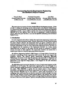
THE METHODOLOGY The following software development approach evolved to address the needs of the 00 developer, while at the same time ensuring that the user’s needs and requirements were incorporated into the resulting software. The user interface plays a pivotal role in the development process and is the main focus for most of the developers, particularly during the initial phases of each project. The process is shown in Figure 1. Requirements Analysis
OMT is a methodology for modeling systems that incorporates three different viewpoints that contain information about the structure and behavior of the problem domain: the object, the dynamic, and the functional model. The object model represents the domain objects, witb their attributes and methods (operations they provide). The dynamic model represents the changing states of an object and the sequence of the states of the objects. Lastly, the functional model represents the flow of data through the model and indicates the operations performed on the data. System development therefore begins with identifying objects, followed by representing the objects’ states and transitions between states, and finally, determining whem the objects get their information and what they do with it. Rumbaugh [6] suggests that the object model should encompass all of the objects of the system, while only the more complicated and critical objects need to have state and functional models.
HFE AND OMT While a number of 00 researchers have proposed methods for collecting such information [7] [8], most notably Jacobson’s Use Cases[4], no method was adequate to use as the model for our development. Like those who have preceded us, we developed our own method based on OMT. During the early stages of our development it was clear that the traditional human factors methods used to collect and convey user requirements were not adequate for our development efforts. Previous projects followed the Hunt and Maddox [9] meW. creating a system objective document (SOD),a task description document (TDD), and a functional descriptive document (FQD). (An application of this methodology is described in [lo].) The develop ment of the user interface dialogs followed the creation of the documents. The developers found that they did not have an adequate understanding of the problem domain to create the object, state, and functional models needed for implementation. The documentation concentrated mort on documenting the user tasks and requirements and did
324
.c
I
User Interface Design
I user Interface Implementation
I
I
Data Base Development
I f User Interface and Data Base Coupling Test
.c
Release Figure 1.
REQUIREMENTSANALYSIS User and system requirements are gathered as the first step in the development process. Interviews are conducted where user task and information requirements are gathered. The user’s expectations of the type of functionality that should be provided by the system are incorporated into a Systems Objective Document. This document is primarily used by the human factors engineer as a mechanism for keeping track of the desired features. Some users review this document to ensure completeness. (For a complete description of this document, see [SI.)
-
User Object Model An object model representing the user’s view of the problem domain is constructed, based on the information gathered during the initial interviews. The objects in the model contain information about the objects and the actions a user would expect to perform on the object. The user’s object model is not intended to be used to implement the system; it is generated to validate the functionality that the user sees occurring in the problem domain. The User Object Model is an additional method of ensuring that the problem domain is well understood and that all of the tasks that users need to perform
is repeated until a set of dialogs has been created that
are being addressed. Figure 2 contains an example of a user object model.
meets end user needs and expectations.
The User Interface serves as the contract between the development team and the users. The users agree that if the system is delivered as specified in the UI dialogs that their needs will be met, and the developers are given the challenge of implementing the dialogs. The user interface as “contract” has been critical in avoiding the creepingfeafure syndrome that often plagues the software developer and the unexpecfedfeufuresyndrome that is often experienced by the end user when software is delivered.
Print Save
Rename
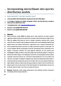
U1 State Model - Object state-transition models are developed for the complex user objects. These state diaClass Code Report
grams are used by the developers during implementation and have little utility when addressing user issues. An example of a state model is presented in Figure 3. The state model identifies the different states of an object and the actions that are needed to transition from one state to another.
Project Number Report
Class code List
Project Number List
Add Class Code Remove Class Codc
Add Project Number Remove Project Number
0 0 + New Report
Add Item or Group
Figure 2.
User Interface - During the development of the User Object Model, work on the user interface (VI) dialogs is started. We have found that users are not very comfortable reviewing object models, which require understanding a notation that is unfamiliar and conceptualizing the implementation. The UI is developed to reflect the information contained in the User Object model. The UI is developed using a GUI builder that produces C++ code, which will subsequently be used by the developers during implementation. The tool supports the creation of dialogs, menus, icons, bibnaps, the assignment of shortcut keys, and control tab order. The tab order and control operation can be tested for individual dialogs using this tool.
-
Defined Report
Save
a Saved Report
Figure 3.
User Interface Specifhtion Document - When the user
U1 Prototype Once the core set of user interface dialogs has been designed, the user interface developer creates a navigation prototype of the dialogs. This prototype ties all of the dialogs together and supports the ability to select menu items and dialog buttons to demonstrate the transition from one dialog to another. The prototype is used to review the user interface design with end users. Users provide feedback regarding missing information, functions, and navigation. The user inputs are used to update the User Object Model and the UI dialogs. The subsequent changes are again reviewed with users. The process
interface dialogs have been completed, a document is written that specifies how the user interface is to be implemented. The i m p b e z ” specification incorpotates the user interface dialogs and describes m u items, business rules used in data validation and verification, formatting of printed output, etc. This document is written at a level of detail that would allow the user interface developer to implemnt the user interEace with little guidance from the user interface deligner. User intailice specification documents have served as critical tools in directing the efforts of contract pmgrammers brought in to implement software and are u s d in the creation of on-line help and user documentation.
325
The information in the specification document identifies the complete functionality of the user interface. The document contains the following information: Menu Structure - The menu structure, the action associated with each menu item, and the menu item acceletator are identified. In addition, the availability of each item based on the state of the user interface is defined. The following is an example:
-File New
@en
Major Control Areas and Controls Report T p e This control area contains exclusive choice controls used to indicate the type of report template to be displayed. PART COST radio button - Used to indicate that a Part Cost Report should be displayed. Default selection. EXCEPnoN radio button - Used to indicate that an Exception Report should be displayed. Window Control Buttons This control area contains the command buttons used to operate on the New Report dialog. DoNE command button Results in the display of the appropriate report dialog based on the selection made. CANCEL command button - Disregards any changes that have been made to the New Report dialog and returns the application to the state that it was in prior to the display of the dialog.
-
Displays the New Report dialog used to indicate the type of report being created Shortcut - Ctrl+N Displays the Open Report dialog used to access a report that has been saved. Shortcut - Ctrl+O
Tool Bur - The controls on the toolbar are identified, as well as the action associated with each control.
RUNREPORTcommand button - Displays the Run Report dialog.
Dialogs - A copy of each dialog is included with a description of its purpose and how the dialog is accessed. The rules for validation of information entered and a description of the actions that should occur when an error condition occurs are identified.
Each data input and display control on the dialog is identified along with its type and default setting. Finally, the dialog command buttons are described and the actions that result from activation are defined. The following is an example: New Report Dialog Description: Dialog used to open a new report dialog. Access: The New menu item in the File Menu or the New icon on the Merlin toolbar.
DEVELOPER DESIGN AND IMPLEMENTATION When the user interface design has been completed, the software developers begin working on their object, state, and functional models. The user object model is used as a guideline, but the model lacks the implementation detail needed to implement software. The developer's design includes two models: one that represents the problem domain (similar in content to the user object model) and the other that represents the user interface. The two models are related during the implementation through the user interface objects communicating with the problem domain objects. The information contained in the User Interface Specification Document is used by the user interface developer to assist in the construction of the User Interface model. The specification is used as a guideline to create the inheritance relationships that reduce development time and facilitate code reuse. An effort is made both by the user interface designer and the developer to make sure that the user metaphor is adhered to and that the layout and content of the dialogs are consistent.
-
OBJECT-ORIENTED DEVELOPMENTTEAM Our software development team has evolved into an ob-
ject-oriented team. member of the team has a particular role in the devetopment process with required inputs and consistent, rehble outputs. Figure 4 identifies the members of the development team and their responsibilities. The members of the team do not need to know how the operations are completed by other members of the team,but merely that the inputs provided will have the information necessary to complete their jobs and to produce the results needed by the next team member.
326
uler Inputs axpeaed Ruults
DalnBueQUcricr Clknt - Smer Canmunicatroa
f- ~
Location ~ t l
REFERENCES
LESSONS LEARNED We have found the use of OOT to be very beneficial. The system that was begun in 1991 by four developers now has a world-wide user base of over 4oO0, is available 24 hours a day, seven days a we&, and requires little or no training. The success of this project has allowed the group to add additional developers (two new hires, one contractor) and to work on multiple prsjects (cmntly 6). Modifying the user interface design p m s s through the incorporation of a user object model and state models has improved our ability to sham information about the problem domain, improved cycle time, and less implementation support by other team membezs is required. Projects arc now scheduled so that usq interfaee design on a IKW project is begum while the software for the previous project is being irnplemented. Tbis provides an easy transition from project to project, reducing the lull that sometimes occurs between projects. The one major difficulty for the HFE using OOT is the lack of tools that support their efforts. The OOT tools am designed around the needs of the software developex, not those of the HFE. The lack of tools makes requirements tracing difficult, as well as the construction of the UI prototype and the uset interface specification document. Developing a prototype still requires software developg intervention to make the screens display at the appropriate times. Writing the specification quires the use of word processing software. %@cant work is required when a change is made to the user interface dialogs after tbc document has been mated. The new dialogs must be captured and inserted into the document and the text must be changed. Having a tool that would support the motation of the user interface dialog during construction atd would produce the specification on demand would be very beneficial.
[ 11 Capper, N.P., Colgate, R.J., Hunter, J.C.,
and Martin, F. The Impact of Object-oriented Technology on Softw m Quality: Three Case Histories. IBM Systems Journal. Vol. 33, 1994. [2] Pei, D. The Secrets to Object Success. Computing Canada. Vol. 19,1993. [ 3 ] Amura, C. Where Object Technology Fits In. Digital News & Review. Vol. 19,1993. [4] Jacobson, I., Christerson, M., Jonsson, P., and Overgaad, G. Object-Oriented Sofnvare Engineering, A Use Case Drive Approach. ACM Press and Addison-Wesley. 1992. [5] McDaniel, SE.,Olson, G.M., and Olson, J.S. Methods in Search of Methodology Combining HCI and Object Orientation. Human Factors in Computing Systems, CHI ‘94 Conference Proceedings. ACM and Addison-Wesley publishing Company, 1994. [6] Rumbaugh, J., Blaha, M., hmerlani, W.,Eddy, F., and Lorensen, W. Object-Oriented Modeling and Design. PrentiCe-Hall. 1991. [7]CO& P. and Yourdon, E. object-Oriented AnaZysis (2ndEdition). Ptentice Hall, Englewood Cliffs, NJ, 1991. [8] Shlaer, S.and Mdor, S.J. An objectdented approach to domain analysis. hj3wup.e Engineering Notes. Vol. 3, 1989. [9] Hunt, R. and Maddox, M. A Practical Method for Designing Human-Machine System Interfaces. Proceedings of the 1986 IEEE International Conference on Systems, Man, and Cybemctics. 1986. [lo] Allen, D.M.Designing for the User: Application of Human Factors Design h@hods to the Rapid Development of a Semiconductor Specification System. Ergonomics of Hybrid Automated Systems ZZ. Elsevia Sciences Publishers. 1990.
327
-