Increased availability and optimization of calciner performance due to automation. Michael Missalla, Dr. Jan Jarzembowski, Roger Bligh, Dr. Hans Werner ...
Light Metals 2009 Edited by TMS (The Minerals, Metals & Materials Society), 2009
Increased availability and optimization of calciner performance due to automation Michael Missalla, Dr. Jan Jarzembowski, Roger Bligh, Dr. Hans Werner Schmidt Outotec GmbH, Oberursel / Germany Keywords: Alumina Calciner, CFB calciner, Operation, Automation
Abstract In the last 30 years, Outotec has installed more than 50 calciners worldwide. Over the years the operation was improved significantly and thus also availability was raised. Real costs for instrumentation and control systems have also reduced over this period, thus encouraging the installation of more instrumentation, data analysis and better process monitoring. More recently, the trend has been towards full automation of activities like capacity load changes while maintaining other performance and product quality related parameters within specification. Other examples of improved automation are the use of advanced control loops with multiple input, while preheating and shut down of the calcination plant can be achieved with just the push of a button. The benefits of improved automation include improved availability through avoidance of operator error, reduction in manpower for process control related tasks and reduced requirement for field adjustment in potentially hazardous areas. The implementation of multivariable control strategies in recently commissioned plants and comprehensively engineered control concepts are described. Furnace temperature feed forward control, automated pre-heating, start-up, gas and solids purge, equipment protection monitoring, and automated protective measures for operational stability and plant trip prevention are presented. Introduction In line with the trend towards larger alumina refinery size, Outotec’s customers have also requested calciners with steadily larger unit capacities[1],[2]. For example, Outotec has recently commissioned two large CFB calciners with a design capacity of 3300 tonnes per day (tpd) at the alumina refinery in Alunorte, Brazil which design was based on the existing plants D and E. With the start up of the calciners D and E in 2006, the team of Alunorte and Outotec set a new benchmark in terms of short duration until the plant could operate with full production [3]. The start up of the new calciners F and G in 2008 made this former record a routine. With these calciners Alunorte now operates in total seven alumina calciners based on Outotec’s Circulating fluidized Bed (CFB) technology [4]. The overall production capacity of 6.3 million tons per year (tpy) makes Alunorte the world’s single biggest alumina refinery. Importantly for the customer, calciners F and G have proven to be easier to operate and control than their predecessors despite the
similar design and layout. This improvement in operability is mainly due to an increased level of automated protective measures which lead to fewer operator mistakes and therefore higher availability and improved safety[5]. Further examples are the two recently commissioned 3500 tpd calciners at the Rio Tinto/Alcan refinery in Gove, where a number of advances in automation were implemented, especially in the area of preheat burner and fuel control. As a result, these calciners have proved to be significantly easier to operate than their predecessor, despite their larger capacity. The target and goals for automation can be formulated as: • • • •
Reduced operational risk Reduced operator pre-occupation with standard tasks Improved operational stability and product quality Reduced operating cost
Risk to personnel, equipment and plant productivity resulting from incorrect/inappropriate operation of the plant can be reduced regardless of the individual operator skills by the implementation of pre-defined and approved procedures. Automation of operating and control functions plays an important part in achieving this target by taking predetermined actions directly, and providing diagnostic information to the operator. The introduction of automated procedures to prevent plant trips leads to an increased availability and throughput of the calciner [6]. Automation also helps operators to focus on overall site performance by reducing their pre-occupation with standard tasks like following a pre-heating curve according to a set profile or load change the load of a calciner.
Moreover, the improved operational stability resulting from advanced automation techniques leads to a more stable product quality, even under conditions where the process is being disturbed by external upset conditions. Automation can be further divided into pre-operational, operational and post-operational activities. Pre-operational activities consist of preheating, purging and preparation activities. While post-operational activities deal with all the stop activities to bring the equipment into a defined status as required by the user. Operational activities are for example start up and production. In the operational part protective measures for operational stability and plant trip preventions are implemented. For example, trip prevention measures prevent operators from entering data
which would lead to a major upset or trip of the calciner. Besides trip conditions are monitored and pro-active measures are taken from the control system, e.g. the limitation of fuel with respect to a safe fuel/air ratio [7]. Process Description
The conveying air cleaned in the airlift cyclone is delivered via ducts to the secondary air cyclone and serves finally as combustion air. The hydrate entering the venturi preheater of the second preheating stage is mixed with the hot waste gas leaving the recycling cyclone and is dehydrated by the heat contained in the hot gas In the cyclone, which is arranged downstream of the venturi preheater, the flow of gas and solids will be separated. From the cyclone, the pre-calcined alumina is delivered into the fluid bed furnace through the material feeding line. The waste gas leaving the cyclone of the second preheating stage is conveyed to the venturi preheater or the first preheating stage where it assumes the above mentioned function. Calcining Stage
Figure 1: Typical flowsheet of a Circulating Fluid Bed (CFB) calciner. In the flowsheet (Figure1) the central piece of equipment is the furnace group in the form of a CFB which is the core process for the calcination. Upstream the furnace group, heat is recovered by the feed hydrate from the off-gases in the two preheating stages. Downstream of the calcination, the alumina solids are cooled down in the cooling stages before being discharged to the alumina storage. Preheating Stage I From the hydrate feed bin, the hydrate is discharged by a screw feeder. The screw feeder delivers the material into the venturi preheater of the first preheating stage. There the solids are mixed with the waste gas, which leaves the cyclone of the second preheating stage. The heat contained in the waste gas evaporates the entire surface moisture of the hydrate. The preheated hydrate entrained with the waste gas is conveyed into the two-stage electrostatic precipitator (ESP). In a first mechanical stage of the ESP parts of the entrained solids are precipitated. The rest of the solids enters the second stage of the ESP together with the waste gas. The waste gas is finally cleaned by means of electrostatic precipitation before it leaves the process to the atmosphere. The solids precipitated in the second stage by electrostatic precipitation are conveyed to the bottom of the mechanical stage by means of screw conveyors. The solids are then fed into an air slide. Preheating Stage II The air slide discharges the hydrate into the sending pot of the pneumatic elevator where the hydrate is conveyed by air to the airlift cyclone. The main portion of the discharged solids is delivered via a discharge seal to the lower part of the venturi preheater of the second preheating stage.
The final calcination of the preheated and partly dehydrated hydrate takes place in the fluid bed furnace. The required heat for calcination is generated by direct combustion of fuel in the fluid bed. For that purpose, dedicated retractable oil lances for heavy fuel oil will be installed. Part of the air quantity required for combustion is introduced through the nozzle grate as primary air, and the remaining air is added above the grate as secondary air. Due to the intensive mixing and heat exchange that takes place in the fluidised bed, the furnace temperature adjusts itself as a mixed temperature between the combustion temperature and the solids temperature, and is kept steady at a pre-set level. In the lower furnace zone, between the grate and the secondary air inlet, a fluid bed of high solids concentration is adjusted. It favors the combustion of the fuel and increases the mean retention time in the calcining furnace. In the upper furnace zone the internal recirculation of the solids causes a continuous reduction of solids concentration until a relatively low concentration is reached. With this solids concentration, the hot gases enter the recycling cyclone where they are separated from the solids. The hot alumina, which is separated in the recycling cyclone passes through the seal pot and re-enters the fluid bed furnace. The recirculation of the solids leads to uniform and practically identical product - and gas temperatures in the entire calcination stage, which consists of the fluid bed furnace, recycling cyclone and seal pot. The fluidisation of the solids in the seal pot, which is required for re-circulation is done by means of the seal-pot blower. A partial product stream is taken from the circulation system and discharged to the cooling stage by the water-cooled discharge lance. The alumina, which is discharged from the calcining stage is cooled in two direct cooling stages each of which consists of a liftduct and a secondary air cyclone. The third cooling stage is designed as a fluid bed cooler and mainly relies on indirect heat transfer. Cooling Stage I The alumina coming from the calcining stage is first mixed with pre-heated air in the liftduct 1 and conveyed into the secondary air cyclone 1. At the same time the air is heated from the temperature of the second cooling stage to the temperature of the first cooling stage. This air is routed from the outlet of the secondary air cyclone 1 to the CFB system as secondary air and used for combustion.
The alumina discharged from the bottom of the secondary air cyclone 1 is fed into the liftduct 2 via a pressure seal. In this liftduct the alumina is mixed and further cooled with secondary air coming from the fluid bed cooler and additional air coming directly from blowers. It is then conveyed into the secondary air cyclone 2 from where it is discharged into the fluid bed cooler. At the same time the secondary and additional air are pre-heated to the temperature of the second cooling stage and then routed to the bottom of the liftduct 1. Cooling Stage III In order to achieve a low specific heat consumption during the calcining process, there is further heat recovery in the air-cooled part of the fluid bed cooler. Primary air is pre-heated by indirect heat exchange in a counter-current flow to the alumina, at the same time the alumina is cooled. At the outlet of the fluid bed cooler the alumina is discharged to a mechanical or pneumatical transport system via a pressure seal. The primary air delivered by blowers is first pre-heated in the fluid bed cooler and then introduced into the fluid bed furnace through the nozzle grate of the furnace. Blowers deliver the secondary air for the fluidisation of the fluid bed cooler. The secondary air is distributed to the compartments of the fluid bed cooler in such a way that a uniform degree of fluidisation is obtained. In the liftduct 2 the preheated air is supplemented with additional air, which is also delivered from blowers. Pre-Operational Activities Fully Automated Gas- and Solids Purge Safety standards usually required a gas purge prior to the restart of a calciner. In addition to the gas purge a solids purge with controlled solids discharge from the plant is recommended from an operational point of view in order to achieve defined restart conditions. All recently commissioned Outotec CFB-calciners provide automated purge sequences which supervise the gas purge and solids discharge from the entire plant. Relevant equipment will be automatically started, valves opened as well as flow and pressure controllers set to designated purge set values. The controlled solids purge is designed to retain a certain solids inventory in the furnace group in order to achieve better temperature stability when restarting the hydrate feed. Fully Automated Preheat Burner and Burner Management System for Fuel Injection Lances
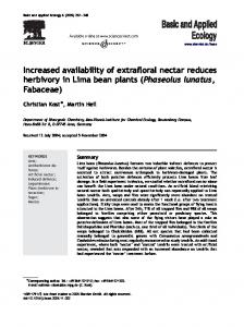
Distributed Control System (DCS) and are also monitored by a Safety Instrumented System (SIS) with an implemented Burner Management System (BMS). To put the preheat burner into operation, the operator at the panel can order the BMS via the DCS to start the burner, which is done then by a fully automated sequence. Once the burner is started successfully, the panel operator can modulate the burner load to heat up the calciner. The degree of automation now enables swifter heat up of the calciner after a trip. New calciners equipped with fully automated preheat burners will be automatically preheated according to a predefined heat up curve (e.g. 70 K/h). Thus no further panel operator action will be required during preheat of a calciner. After the automated preheating cycle, the operator will be enabled to initiate the automated plant start sequence. Further, the lances are controlled in a similar way by the BMS. Once the calciner furnace is above the minimum safe ignition temperature the operator starts up the fuel injection system in a similar manner to the preheat burner. When the lances are set in operation and the fuel demand is increasing or decreasing then the appropriate number of lances are started or stopped automatically. Therefore, an operator is no longer needed for the lances and this consequently speeds up the process of putting sufficient lances in operation. This approach was applied in the design of the calciners in Gove where the customer wanted the possibility for a dual fuel system to be able to change from one fuel to another without reducing the production rate of the calciner. When fully implemented, it will be possible for the operator to mix the fuel supply according to the energy demand, but also to the available combustion air independent from the different air requirements of the fuels. The fuel flows will be controlled by the total energy demand to maintain the calcination temperature. Figure 2 demonstrates the control philosophy. Here the percentage of delivered energy is plotted versus a control value set by the operator. A control value of 0-5% means only heavy fuel oil is supplied and a value of 95100% corresponds with only natural gas supply. Every value between these margins corresponds with a percentage of the total energy demand by the furnace temperature control system being delivered in the form of heavy fuel oil. The difference represents the energy demand supplied in the form of natural gas. Percentage of Energy Delivered by Fuel
Cooling Stage II
100
NG
75 50
HFO
25 0 0
25
50
75
100
Operator Choice of NG-Ratio on Energy Demand
Each of the new calciners for Rio Tinto Alcan in Gove is equipped with one preheat burner and four lances for heavy fuel oil (HFO). Additionally they have a separate set of natural gas (NG) lances in anticipation of natural gas being available to the site at a later stage.
Figure 2: Control of fuel mixture for a dual fuel operated calciner
To improve the operability of the calciners, the preheat burner and the fuel injection lances are fully automated through the
Automated Plant Start Sequence
Operational Activities
Outotec’s recently commissioned calciners provide semiautomated plant start sequences and procedures which are guiding the operator through the plant start up. In future, new installations will be equipped with fully automated start up sequences which will – after being initiated by the panel operator – automatically introduce fuel, start all relevant equipment, commence hydrate feed and ramp the plant up to a preselected capacity.
material from 100 % of design capacity to about 25 %, the furnace temperature was kept stable, thus maintaining a constant product quality.
Improved Furnace Temperature Control The temperature in the furnace is controlled by the fuel oil flow. However it might be possible that the amount of hydrate been fed to the furnace is fluctuating. The fluctuation can be caused by an uneven ESP solid discharge or even an uneven hydrate feed via the hydrate feed screw. If the feed to the furnace is reduced the temperature will rise. The velocity of this rise is dependent on the amount of hydrate missing and on the response time of the thermo couple. However this could lead to unacceptable high or low temperatures finally resulting in a plant equipment safety trip. To improve the furnace stability under the conditions described above, Outotec has implemented a furnace temperature feed forward control strategy where the hydrate mass flow is measured just before it enters the furnace. Fluctuations in this signal are used in a feed forward loop to increase or decrease fuel flow as appropriate. Figure 3 illustrates the re-start procedure of a CFB calciner over a time period of several hours. The diagram shows the furnace temperature, the furnace temperature set point, the heavy fuel oil flow (HFO) and the hydrate feed during the re-start period up to nominal load. It can be seen that the fluctuation of the furnace temperature is even with load changes from almost zero hydrate feed capacity to nominal load in the range of 10 degrees.
Figure 4: Rapid load change in a calciner from 235 t/h to 60 t/h within 10 minutes. Start-up Performance of Alunorte The latest CFB calciners –2 x 3500 tpd at Gove and 4 x 3300 tpd at Alunorte - have proven to be very easy to operate and fast in start-up from preheat to full capacity. This is demonstrated in Figure 5, where the capacity is plotted versus the time in minutes. At t = 0 min, preheating is finished and furnace temperature is approx. 830°C, ready for the start of the heavy fuel oil lances. It takes only 100 minutes from the start of the heavy fuel oil lances to 100% of the calciner design capacity.
Calciner Capacity in (Actual Fuel Flow)/(Full Capacity Fuel Flow), -
120
Figure 3: Furnace temperature feed forward control. Max. deviation from set point ~10°C.
Load Change in a Calciner In Figure 4 a load change in the calciner from 235 t/h to 60 t/h of hydrate feed within 10 minutes is shown. This rapid load change was necessary due to a failure in the hydrate delivery to the calciner. It can be seen that fuel oil flow follows the hydrate flow with a certain time delay. Even with this rapid change in feed
100
80 60
40 20
0 0
50
100
150
200
250
300
350
400
time, min
Figure 5: Calciner capacity over time after re-start.
The characteristics of some important temperatures within the calciner are shown in Figure 6. The furnace temperature increases rapidly after starting the oil lances. The temperatures in the feed preheating stages are established within seconds of balancing hydrate feed to the heat generation in the furnace. On the other hand, temperatures in the alumina cooling stages increase to
nominal values comparatively slowly due to the delay in discharge of alumina from the furnace.
combined with a controlled shutdown sequence in order to achieve a safe and defined plant status and increased reliability factor [6] Conclusions
Temperature as percentage of value at steady state, %
120
The reduction in real instrumentation costs has encouraged the installation of more instruments leading to a better monitoring of the process. Using this additional data, several automated procedures were developed. The targets for this automation were the reduction of operational cost and risks. Besides the preoccupation of operators with standard tasks will be significantly reduced
Furnace 100
80
Cooling Stage 1 60
Cooling Stage 2 40
The automation activities are divided into pre-operational, operational and post-operational activities and samples from industrial scale plants for each area are given. Even upset conditions do not lead to a trip of the plant.
20
0 0
50
100
150
200 time, min
250
300
350
400
Figure 6: Important process temperatures after re-start of calciner.
When the plant is shut down, all solids are removed from the vessels to the fluid bed cooler by means of the blowers. This is done to avoid blockages during restart. The alumina discharge from the calcining stage is closed at the beginning of hydrate feed and stays closed until enough inventory is built up in the furnace. Figure 7 shows two of the latest calciners operating in Gove, Australia were the above described technology is already applied.
The new developed furnace temperature feed forward control assures constant furnace temperatures even at rapid and significant load changes. Product quality from the CFB calciner can therefore be kept consistent not only at constant loads, but also during the load changes. Acknowledgment Outotec would like to thank the engineers and operations personnel of Alunorte and Rio Tinto Alcan for their professional support and appreciates their contributions to the recent developments in CFB technology. References [1] D.J. Brodie, H.W. Schmidt, “Custom Design Fluid Bed Calciner for Nabalco Pty. Ltd.”, Proceeding of 5th International Alumina Quality Workshop, (1999), Bunbury, Australia [2] Y.Yetmen, H.W. Schmidt, Large Units for Alumina Calcination Plants with improved Technology “ Int. Conference on New development in Metallurgical Process Technology Proceedings VDEM, pp 369-375 (1999) [3] Michael Missalla, Cornelis Klett, Roger Bligh, “Design Developments for Fast Ramp-up and Easy Operation of New Large Calciners”, TMS Light Metals (2007) [4] A. Squires, “Origins of the Fast Fluid Bed, Advances in Chemical Engineering”, Vol. 20, Fast Fluidisation (Ed. Kwauk, M.), Academic Press (1994), pp 4-35
Figure 7: Two calciners 3500 tpd capacity each. Gove, NT, Australia
Post-Operational Activities Automated Plant Shut Down Post-operational activities are currently semi-automatically and include sequences to stop blowers, ESP rectifiers, rappers, discharge conveyors and other equipment. In future applications the semi automated sequences will be further developed and
[5] H.W. Schmidt, M. Ströder, G. Singh, M. Sant’ana, J. Ribeiro, J. Piestrzeniewicz, M. Cable, “Improved Health and Safety Conditions and Increased Availability in Large Alumina Calcining Units”, TMS Light Metals (2005) [6] P.Hiltunen, R.Bligh, C.Klett, M.Missalla, H.W.Schmidt “How to Achieve High Availability with Large Calciners and Avoid Unforeseen Downtime”, TMS Light Metals (2008) [7] L.Reh,” New and Efficient High Temperature Process with Circulating Fluid Bed Reactors”, Chem. Eng.Technol. 18 (1995) page 75-89