Experiment was carried out at the PALS iodine laser. .... J. Grun, S.P. Obenschain, B.H. Ripin, R.R. Whitlock, E.A. McLean, J. Gardner, M.J. Herbst and J.A..
36th EPS 2009; S.Borodziuk et al. : Indirect two-step method of acceleration, applied to metallicfoils of diff...
2 of 4
ablative plasma. That method appeared to be much more effective than the usually applied conventional method of acceleration. In this paper the “Cavity Pressure Acceleration Scheme” (CPAS) is proposed and tested. Pressure induced by laser action inside the target cavity constitutes here the most important factor of foil acceleration. It was expected that such target construction could improve absorption of the laser radiation and to rise efficiency of foil acceleration process. The experiment was conducted on Prague Asterix Laser System (PALS). It is demonstrated possibility both to accelerate a thin-foil target to the higher velocity than that attainable in the ”classic” way (in the comparable experimantal conditions) and simultanously to avoid a problem of diminishing of the foil mass during the process of acceleration. The special attention is paid to the problem of acceleration of very thick (300 or 500 m) foils. 2. Experimental set-up and conditions The experiment was performed with the PALS iodine laser. The following laser parameters for targets irradiation have been chosen: the first harmonic of laser radiation ( =1.315 m) with an energy in the range of 120-500 J, a pulse duration of 250 ps (FWHM) and focal spot diameters at the target surface 100 – 200 m. The “cavity type” targets consisted of a massive Al slab with a cylindrical hole of 600 m in diameter and 100 m in depth as well as 10, 300 or 500 m thick Al foils covering a hole. So, the targets constituted a closed cavity. To introduce the laser radiation into the cavity a 200 m diameter pinhole in the foils was bored. This pinhole size ensured effective beam passing through the pinhole. Construction of the targets is shown in Fig. 1. To study the flayer foils dynamics and deformation a three-frame shadographic/interferometric system was employed. The delay between frames was set at 3 ns.
Fig 1.Construction of the “cavity type” targets used in the experiment .
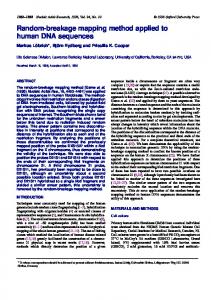
3. Experimental results Investigations of the 10 m thick Al foil acceleration were carried out for the three laser energies mentioned above. The foil reached velocities in the range of (2-3) 107 cm/s. As our attention was mainly devoted to the thick foils so the results concerning these foils are presented here in greater detail. In Fig. 2 three sequences of shadowgrams for the 300 m thick foil corresponding to laser energies of 120, 300 and 500 J and a sequence for the 500 m thick foil at laser energy of 120 J are presented. One can see deformation of the foils and their motion along the axis. On he basis of these shadowgrams the velocities of the 300 m thick foil for the laser energies of 120, 300 and 500 J were determined to be equal to 0.7 107 cm/s, 1.0 107 cm/s and 1.4 107 cm/s, respectively. On the other hand, from the simple theoretical analyze it can be found the following relationship between two velocities for two different laser energies: v1/v2 = (E1/E2)1/2.
36th EPS 2009; S.Borodziuk et al. : Indirect two-step method of acceleration, applied to metallicfoils of diff...
3 of 4
Fig. 2. Sequences of shadowgrams for the 300 m thick foil at different laser energies (a) and for the 500 m thick foil at energy of 120 J (b).
Fig. 3. Theoretical (continuous line) and experimental dependences: a) of the 300 m thick Al foil velocity on the laser energy and b) of the velocity of Al foils on their thickness.
The diagram in Fig. 3a presents the theoretical change of the foil velocity with decreasing laser energy in relation to the energy of 500 J. It is seen that the experimental points correspond to the theoretical graph. Hence we can suppose that in the case of thick foils the same proportionally part of plasma energy is transferred into the foil kinetic energy. In Fig. 2 the first and last sequences correspond to the same laser energy (120 J) but represent different foil thicknesses (300 and 500 m). The velocities corresponding to both thicknesses differ slightly (in both cases the velocities are roughly on the level of 0.7 107 cm/s). Using the same theoretical analyze as above we can get the relative dependence between the foil velocity and the foil thickness (df) as follows: v1/v2 = (df2/df1)1/2. This dependence related to the 500 m thick foil is drown in Fig. 3b. One can see that in the case of the thick foils the foil velocity grows weakly with the decreasing foil thickness. The velocity should increase very fast for the foil thickness smaller than 100 m. The points marked in this Figure correspond to the experimental data. The thin foil point diverges essentially from the theoretical prediction. It follows from the fact that density of the accelerated foil drops drastically as a result of its fast expansion. The maximum velocity is reached for a (relatively) thin 10 m Al foil much faster (for times t < 5 ns) than for thick (100 – 500) m foils. The optical shadow boundary movement observed in shadowgrams gives in fact an information about velocity of the determined density layer but not the foil as a whole. It means that the average foil velocity (integrated over all foil mass) is in fact much lower than the velocity estimated from the motion of target optical shadow. For thin foils it
36th EPS 2009; S.Borodziuk et al. : Indirect two-step method of acceleration, applied to metallicfoils of diff...
4 of 4
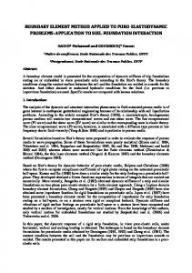
also causes that the low density (i.e. invisible part of the accelerated foil) grows fast what gives an effect of slower movement of the rest (visible) foil. This is why there is impression that the thin foil velocity decreases at later times. The acceleration of macroparticles to high (thermonuclear) velocity, “not forgetting” about its density, is general and essential problem from the point of view of their possible applications in the IFI area. One of the possible ways of improvement of this situation is acceleration of macroparticles in cylindrical or conical channels as it is shown in Fig 4.
Fig 4. Modified cavity target which can be used as a macroparticle accelerator (taking advantage of CPAS method) and applied as an ignitor for laser fusion experiments.
4. Conclusions We propose a new, very effective scheme, which can be applied to accelerate macroparticles to high velocities with efficiency not observed in classic ablative experiments. Cavity pressure is able to accelerate macroparticles very efficiently in arbitrary direction. The above results clearly show that the most important element of the applied method of acceleration is pressure produced in the target cavity. So, this mechanism can be named as a “Cavity Pressure Acceleration Scheme” (CPAS). Our results (high velocity of accelerated foil/macroparticle or possibility of accelerating of heavy macroparticles) show that they can be applied to study impact fast ignition and impact fusion problems. This method leads to significantly higher velocities of flyer foils than those obtained by traditional way (ablative acceleration scheme) in similar experimental conditions. It follows from the fact that CPAS allows to use almost all absorbed laser energy (neglecting the energy of the shock wave propagating into the solid target). Also the hydrodynamic efficiency of the energy transfer to the flyer foil is much higher. CPAS enables acceleration by laser of very heavy macroparticles (df ~ 10-1 g/cm2) to velocities of ~ 1 107 cm/s (authors do not know similar results in the literature) whereas conventional ablative acceleration of that foil was completely unsuccessful (the foil has even not started). A very high hydrodynamic efficiency obtained in CPAS experiment may be a chance to construct an impact ignitor for laser fusion experiments. Another advantage of CPAS method is that conversion of laser radiation to higher harmonics it is not necessary. Generally, for the moderate laser light intensities (Il ~ 1015 W/cm2) results (velocity, hydrodynamic efficiency) obtained for the first harmonic are (at least) as good as those for the third harmonic of iodine laser, which was previously used in our experiment. References: 1. J. Grun, S.P. Obenschain, B.H. Ripin, R.R. Whitlock, E.A. McLean, J. Gardner, M.J. Herbst and J.A. Stamper, Phys. Fluids 26 (2), 588 (1983). 2. K. Eidmann, F. Amiranoff, R. Fedosejevs, A.G. Maaswinkel, R. Petsch, R. Sigel, G. Spindler, Yung-lu Teng, G. Tsakiris, and S. Witkowski, Phys. Rev. A 30(5), 2568 (1984). 3. S. Borodziuk and J. Kostecki, Laser and Particle Beams 8, 241 (1990) 4. S. Borodziuk and J. Kostecki, J. Tech. Phys. 32 (1), 73 (1991) 5. M. Murakami and H. Nagatomo, Nucl. Inst. and Meth. Phys. Res. A 544, 67 (2005). 6. S. Borodziuk, A. Kasperczuk, T. Pisarczyk, J. Ullschmied. E. Krousky, K. Masek, M. Pfeifer, K. Rohlena, J. Skala, and P. Pisarczyk: Appl. Phys. Letters 93, 101502 (2008).