Journal of
Manufacturing and Materials Processing
Article
Induction Heating Validation of Dieless Single-Point Incremental Forming of AHSS Amar Al-Obaidi 1, * 1 2
*
ID
, Verena Kräusel 1 and Dirk Landgrebe 2
Institute of Machine Tools and Production Processes IWP, Technische Universität Chemnitz, 09126 Chemnitz, Germany;
[email protected] Fraunhofer-Institute for Machine Tools and Forming Technology IWU, 09126 Chemnitz, Germany;
[email protected] Correspondence:
[email protected]; Tel.: +49-371-531-34693
Received: 12 July 2017; Accepted: 21 August 2017; Published: 23 August 2017
Abstract: Advanced high-strength steel (AHSS) is subject to a high deformation in geometry due to spring-back and high forces during forming. Therefore, dieless single-point incremental forming supported by induction heating was introduced. When a HCT980C steel part was studied, it was observed that the geometrical accuracy increased by forming using a 15 kW induction power, whereas a high deviation in profile geometry was observed by forming using a 5 kW induction power. The forming forces decreased by 66.63% compared with those resulting from forming at room temperature. At the same time, the HCT980C steel part cracked and failed to reach its designed depth when forming at room temperature. Regulating the tensile strength and hardness of the formed part and preventing their reduction was achieved by increasing the feed rate continuously as a function of the formed part’s growing depth. Moreover, the distribution of the induction heating temperature was reduced by introducing the new forming strategy. A cone wall angle of 70◦ was flexibly formed from a HCT980C steel sheet when the new strategy was applied. Keywords: dieless single-point incremental forming; induction heating; geometrical accuracy; formability
1. Introduction Dieless single-point incremental sheet metal forming (SPIF) by a tool having a single point of contact is a highly adaptable process whereby the part is formed by the movement of a hemispherical tool along a characterized path. SPIF technology is different from other sheet metal forming methods, such as spinning, piercing, deep drawing, and bending. The mechanism of SPIF is plastic deformation caused by directing a forming tool via a path on the sheet metal using a computer numerical control (CNC) machine [1]. Since SPIF is a dieless process, it is suitable to form complicated prototype profiles within a short period at low cost. The most popular parts that were made by SPIF have been used in aerospace or medical applications [2]. Due to the feasibility shown by SPIF, new applications were presented, such as applying heat in forming hard-to-form, high-strength sheet metals. A new generation in SPIF has started to apply the heat in different ways during forming to form high-strength sheet metals. Laser heating was investigated by [3] where two moving systems were used: one was a robot to move the tool and the other was a 3D coordinator to guide the laser on the sheet. Furthermore, conduction heating was suggested by [4] to heat the sheet metal by electric heaters for forming a 5083 aluminum magnesium alloy. Another heating method was presented that involved exerting hot oil to increase the sheet metal temperature as described in [5]. In other investigations, an electrical current was applied that passed through the tool to heat up the sheet, which was studied by [6] to form a titanium alloy TiAl2 Mn1.5 .
J. Manuf. Mater. Process. 2017, 1, 5; doi:10.3390/jmmp1010005
www.mdpi.com/journal/jmmp
J. Manuf. Mater. Process. 2017, 1, 5
2 of 10
A hot air medium was tested in [7] as the temperature of AZ31 alloy was increased to 250 ◦ C and formed it into complicated shapes. Resistance heating was suggested by [8], using two tools held by robots: one to form and the other to support and heat the sheet metal to 600 ◦ C. It can be concluded from the literature review that there is no heating method accompanied with SPIF that can increase the sheet metal temperature over 750 ◦ C other than with a laser. However, the laser method was specialized by its complexity. SPIF has still not been implemented widely in industry for numerous reasons, including:
• • • • •
Lack of geometrical accuracy in high-strength produced parts [9,10]; Limited applications, especially for high-strength metals; Lack of suitability for difficult-to-manufacture parts with a perpendicular wall angle, such as deep drawing; Suitable only for prototype manufacturing because of the time consumed during tool travel along its designed path; and Different component properties in comparison to the conventional sheet metal forming technologies.
This paper proposes a method to increase the importance of SPIF by demonstrating induction heating synchronized with SPIF, or induction-assisted SPIF (IASPIF). The availability of a viable induction heating method with SPIF would increase the interest in it. An advantage of our approach is that high-strength sheet metals can be simply formed into complex geometries by adopting a simplified mechanism. 2. Materials and Methods The sheet metal blanks and their specific parameters for our dieless SPIF investigation were tested by many devices to improve the efficacy of the suggested process. It became clear that the process parameters have a very large influence on the experimental results. HCT980C dual-phase steel is well known as an advanced high-strength steel (AHSS) and was investigated using a sheet with a thickness of 1.2 mm. The steel alloy was supplied by ThyssenKrupp Stahl-Service-Centre (Radebeul, Germany). The full specifications and properties of the mentioned steel alloy can be found in [11]. The experimental setup of the dieless single-point incremental forming process assisted by induction heating was the same as that used in [12] and is illustrated in Figure 1. The forming tool material was made from hot-worked tool steel X210Cr12 (1.2080) with a diameter of 12 mm. The tool is fully quenched and hardened to 64 HRC and forming tips with diameters of 6 and 12 mm were used. A high frequency induction generator was used with a maximum power capacity of 50 kW and the magnetic radiation frequency was 325 kHz. An induction coil was connected to the induction generator head which moved simultaneously with the forming tool. A one-turn induction coil utilized in the experiments had outer and inner diameters of 20 and 8 mm, respectively. The coil was made from a rectangular profile with a width of 6 mm shaping the coil face. It also had a depth of 4 mm, as shown in Figure 2. The suggested profile geometry was designed by the SOLIDWORKS software and then exported into a step file to obtain the tool path code that is used by the CNC milling machine. The tool path code program was made by a CAM-software named ESPRIT. A Kistler dynamometer (type 9255Asp) made by Kistler Instrumente AG (CH-8408 Winterthur, Switzerland) was utilized to enhance the resulting forming forces. There were difficulties measuring the generated heat in the assembled system. The thermocouple could not be used because of the continuous movement of both the forming tool on the upper portion and the induction coil in the lower portion of the sheet. Therefore, the induction heating temperature was measured by an infrared (IR) camera (InfraTec type VarioCAM® ) produced by ESW GmbH (Wedel, Germany), which has a measuring range from −40 to 1700 ◦ C. The measuring frequency was 2
J. Manuf. Mater. Process. 2017, 1, 5
3 of 10
Manuf.Mater. Mater.Process. Process.2017, 2017,1,1,55 J.J.Manuf.
33ofof1010
Hz (2 pictures/sec). The IR camera adopted toThe measure the lower ofto themeasure sheet temperature, measuring frequency was Hz (2 (2was pictures/sec). IR camera was adopted the measuring frequency was 22 Hz pictures/sec). camera wasportion adopted to measure thelower lower as in [13]. portionof ofthe thesheet sheettemperature, temperature, as as in in [13]. portion
Figure 1. Experimental setup applied in the investigations for IASPIF process. (a) up Close up of Figure applied in the for IASPIF process. (a) Close of forming Figure 1.1.Experimental Experimentalsetup setup applied in investigations the investigations for IASPIF process. (a) Close up of forming tool and sheet blank; and (b) entire setup. tool and tool sheetand blank; and (b) entire setup. forming sheet blank; and (b) entire setup.
Figure 2. Partial sectional view from induction coil, all dimensions are in mm. Figure 2. Partial sectional view from induction coil, all dimensions are in mm. Figure 2. Partial sectional view from induction coil, all dimensions are in mm.
2.1. Effect of Heat on the Formability of the HCT980C Steel 2.1. Effect of Heat on the Formability of the HCT980C Steel 2.1. Effect of Heat oninthe Formability of the HCT980C Steel As indicated Figure 3, the increase in temperature caused a reduction in tensile strength and As indicated in Figure 3, the increase in temperature caused a reduction in pearlite tensile strength and an increase in ductility due to the transformation of the martensitic phase into and ferrite. As indicated in Figure 3, the increase in temperature caused a reduction in tensile strength and an increase in ductility due tobythe transformation of the to martensitic phase into pearlite and ferrite. These results were obtained heating up the material the desired temperature, soaking up to an increase in ductility due to the transformation of the martensitic phase into pearlite and ferrite. These results were performing obtained bythe heating the The material to the desired temperature, soaking 20 min and then tensileuptest. heating oven was attached to the tensileup testto These results were obtained by heating up the material to the desired temperature, soaking up to 20 min and performing was the tensile Thethe heating wastensile attached the carried tensile out test machine andthen the temperature appliedtest. during tensile oven test. The teststowere 20 min and then performing the tensile test. The heating oven was attached to the tensile test machine machine and temperature was10002-5 appliedbyduring the tensile test.testing The tensile testsmanufactured were carried by out according to the standard DIN EN a universal tensile machine and the temperature was applied during the tensile test. The tensile tests were carried out according Hegewaldto and Peschke,DIN GmbH according standard EN(Nossen, 10002-5 Germany). by a universal tensile testing machine manufactured by to standard DIN EN 10002-5 by a universal tensile testing machine manufactured by Hegewald and Hegewald and Peschke, GmbH (Nossen, Germany). Peschke, GmbH (Nossen, Germany).
J. Manuf. Mater. Process. 2017, 1, 5
J. Manuf. Mater. Process. 2017, 1, 5
4 of 10
4 of 10
Figure3.3. The The effect thethe mechanical properties of HCT980C steel.steel. Rm = Figure effect of ofheating heatingtemperature temperatureonon mechanical properties of HCT980C maximum tensile strength and Ag = elongation percentage. Rm = maximum tensile strength and Ag = elongation percentage.
2.2.Experimental ExperimentalConditions Conditions 2.2. Theexperimental experimentalmethod methodconsisted consistedofofproducing producinga aconical conicalshape shape100 100mm mminin diameterfrom from the The diameter the previously stated steel alloy at both room and elevated temperature. The forming parameters used previously stated steel alloy at both room and elevated temperature. The forming parameters used were follows: were asas follows:
The incremental step depth in the z-direction for the milling machine was chosen to be The incremental step depth in the z-direction for the milling machine was chosen to be ΔD = 0.5 mm. ∆D = 0.5 mm. The starting cone wall angle was 60° then it was increased until failure. The cone depths were • The starting cone wall angle was 60◦ then it was increased until failure. The cone depths were then 50 and 70 mm. then 50 and 70 mm. A graphite powder was sprayed onto the sheet face as a dry lubricating medium because it is • Anot graphite powder sprayed onto the face as a dry lubricating medium because it is not possible to usewas a liquid lubricant at sheet high temperatures. to usedimensions a liquid lubricant highsheet temperatures. possible The original of the at tested blank were 190 mm × 190 mm. • The original dimensions of the tested sheet blank were 190 × 190 mm. No supporting plate was applied in the experiments duemm to the movement of induction coil in • No supporting plate was applied in the experiments due to the movement of induction coil in the the lower side of the sheet. lower side of the sheet. Tensile test samples were cut by a water jet cutting machine from profiles that were formed Tensile samples cut by a water jet cuttingthese machine from were profiles that were formed from • from test a 150 × 150 were mm pyramid. Additionally, samples utilized to investigate the a 150 × 150 mm pyramid. Additionally, these samples were utilized to investigate the resulting resulting strength for the HCT980C steel after induction heating. strength for the HCT980C steel after induction heating. 2.3. Additional Tests to Improve the Feasability of the Suggested Study on the HCT980C Steel 2.3. Additional Tests to Improve the Feasability of the Suggested Study on the HCT980C Steel The formed profiles were scanned by an Atos Core 200 measuring system manufactured by The formed profiles were scanned by an Atos 200 measuring system The manufactured by GOM-Gesellschaft für Optische Messtechnik mbHCore (Braunschweig, Germany). microhardness GOM-Gesellschaft für Optische Messtechnik (Braunschweig, Germany). The microhardness tests were conducted on an M1C automated mbH hardness testing system manufactured by EMCO-TEST tests were conducted on an M1C automated hardness testing system manufactured by EMCO-TEST Prüfmaschinen GmbH (Kuchl, Austria). Prüfmaschinen GmbH (Kuchl, Austria).
•
3. Results and Discussion 3. Results and Discussion The results contained useful information about HCT980C steel behaviour during dieless hot The results contained useful information about HCT980C steel behaviour during dieless hot SPIF. The formability was increased by forming cone wall angles of 62° for HCT980C steel. A new SPIF. The formability was increased by forming cone wall angles of 62◦ for HCT980C steel. A new forming technique was developed by forming with variable feed rates during the operation. Initial forming technique was developed by forming with variable feed rates during the operation. Initial investigations were done without applying induction heating, forming at room temperature to investigations were done without applying induction heating, forming at room temperature to compare compare to the parts that were formed by applying induction heating later at elevated temperatures. to the parts that were formed by applying induction heating later at elevated temperatures. 3.1. The Effect of Induction Power on the Geometrical Accuracy The accuracy of the conical parts that were formed from HCT980C steel was measured by a GOMATOS scanning system as the cone profile was clamped by a fixture to guarantee the exact measuring position, as stated in [14]. The scanned profiles represent the formed parts produced
J. Manuf. Mater. Process. 2017, 1, 5
5 of 10
3.1. The Effect of Induction Power on the Geometrical Accuracy The accuracy of the conical parts that were formed from HCT980C steel was measured by a GOMATOS system as the cone profile was clamped by a fixture to guarantee the exact J. Manuf. Mater.scanning Process. 2017, 1, 5 5 of 10 measuring position, as stated in [14]. The scanned profiles represent the formed parts produced during J. Manuf. Mater. Process. 2017, 1, 5 5 of 10 the experiment. The scanned profilesprofiles were merged and compared with those by theby CAD during the experiment. The scanned were merged and compared with designed those designed the program SOLIDWORKS. The rapprochement between the scanned and the CAD models was done CAD program SOLIDWORKS. The rapprochement between scannedwith andthose the CAD models was during the experiment. The scanned profiles were merged andthe compared designed by the by applying the GOM inspect program. The actual model was placed over the model for done by program applying the GOM inspect The actual model placed the CAD model for CAD SOLIDWORKS. Theprogram. rapprochement between thewas scanned andover theCAD CAD models wasthe comparison. Figure 4 shows the CAD model of the cone shapes used in this study. Each point on the done by applying the GOM inspect program. The actual model was placed over the CAD model for the comparison. Figure 4 shows the CAD model of the cone shapes used in this study. Each point on CAD model was compared with the points inpoints the actual model and thestudy. combined comparison. Figure 4 shows therespective CAD of the cone shapes used in this point on thethe CAD model was compared with the model respective in the actual model andEach the deviations combined of the appeared asappeared color-scaled deviations.points the two CADmodels was compared with the respective in the actual model and the combined deviations ofmodel the two models as color-scaled deviations. deviations of the two models appeared as color-scaled deviations.
Figure used in this study. Figure4. CADmodel modelof of cone cone shapes shapes used Figure 4.4.CAD CAD model of cone shapes usedin inthis thisstudy. study.
The most striking results of the the scanned scannedprofiles profilesand andCAD CAD models The most striking resultscame camefrom fromthe thecomparison comparison of models as as The most striking results came from the comparison of the scanned profiles and CAD models as indicated in Figure 5. The higher the induction power, the lower the difference between the CAD indicated in Figure 5. The higher the induction power, the lower the difference between the CAD indicated in Figure 5. The higher the induction power, the lower the difference between the CAD and scanned profiles. These results correlate satisfactorily satisfactorily with stated andand scanned profiles. These results correlate with Magnus Magnus[15] [15](p. (p.118) 118)which which stated scanned profiles. These results correlate satisfactorily Magnus [15] (p. 118) which stated that a that moreaccurate accurate geometry was formed formed by by a with higher that a amore geometry was higher laser laser power power that thatgenerated generatedhigher higher more accurate geometry was formed by a higher laser power that generated higher temperatures. temperatures. temperatures.
Figure 5. (a) 3D geometrical scan compared with CAD profiles formed by 62° cone wall angle; and Figure 5. (a) 3D geometrical scan compared with CAD profiles formed by 62◦ cone wall angle; (b) quartered showing for different induction heating Figure (a) 3Dsections geometrical scancomparisons compared with CAD profiles formed bypowers. 62° cone wall angle; and and (b) 5. quartered sections showing comparisons for different induction heating powers. (b) quartered sections showing comparisons for different induction heating powers.
The negative deviations presented in Figure 5 mean that the scanned part level is lower than the CAD level. However, the positive deviations express that the scanned part is level is higher Theprofile negative deviations presented in Figure 5 mean that the scanned part level lower than the than the CAD profile level.
CAD profile level. However, the positive deviations express that the scanned part level is higher than the CAD profile level.
J. Manuf. Mater. Process. 2017, 1, 5
6 of 10
The negative deviations presented in Figure 5 mean that the scanned part level is lower than the CAD profile level. However, the positive deviations express that the scanned part level is higher than J. Manuf. Mater. Process. 2017, 1, 5 6 of 10 the CAD profile level.
3.2. The Effect of Induction Heating on the Forming Forces forces are are shown shown in in Figure Figure 66 for for HCT980C HCT980Csteel. steel. The measured forming forces
Figure 6. 6. Force both with with and and without induction heating heating at at aa power power Figure Force in in the the z-direction z-direction during during forming forming both without induction ◦ of 12.5 kW for 62° cone wall angle test samples formed at a 1.5 m/min feed rate. of 12.5 kW for 62 cone wall angle test samples formed at a 1.5 m/min feed rate.
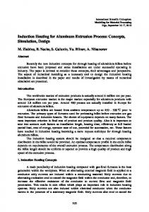
The forces in the z-direction without induction heating (room temperature) exceed 5500 N. The The forces in the z-direction without induction heating (room temperature) exceed 5500 N. forces during induction heating were limited to 1850 N. It is, therefore, not possible to form the The forces during induction heating were limited to 1850 N. It is, therefore, not possible to form the HCT980C steel at room temperature. HCT980C steel at room temperature. The high fluctuation in the forming forces was also discovered by [16]. The pulsing The high fluctuation in the forming forces was also discovered by [16]. The pulsing phenomenon phenomenon in the forming forces was caused by continuous movement of the forming tool on the in the forming forces was caused by continuous movement of the forming tool on the sheet blank. sheet blank. A calibration process was performed to validate the measured forces in the z-axis A calibration process was performed to validate the measured forces in the z-axis direction equal to direction equal to ± 5 N. ± 5 N. 3.3. Influence of Induction Induction Heating Heating on on the the Microhardness Microhardness and and Mechanical Mechanical Properties Properties 3.3. Influence of The maximum maximum tensile tensile strength strength of of HCT980C HCT980C steel steel as as delivered delivered was was 1000 1000 MPa, MPa, but but after after forming forming The at a feed rate of 1.5 m/min and using an induction power of 12.5 kW, the resulting tensile strength at a feed rate of 1.5 m/min and using an induction power of 12.5 kW, the resulting tensile strength decreased to to approximately approximately540 540MPa. MPa.The Theobtained obtainedtensile tensilestrength strengthafter afterforming formingwas wasextracted extractedfrom from decreased a a tensile test sample that was described in Section 2.2. tensile test sample that was described in Section 2.2. The HCT980C HCT980C tensile tensile strength strength was was significantly significantly influenced influenced when when heated heated to to more more than than 750 750 ◦°C as The C as investigated by by[17]. [17].The Thesample sample temperature reached °C when formed at arate feed ratem/min of 1.5 ◦ C when investigated temperature reached 790 790 formed at a feed of 1.5 m/min and using an induction power of 12.5 kW as shown in Figure 7a. At the same time, the and using an induction power of 12.5 kW as shown in Figure 7a. At the same time, the formed cone formed cone was divided into 3 equal zones as shown in Figure 7b, and the microhardness values of was divided into 3 equal zones as shown in Figure 7b, and the microhardness values of each zone were each zone werefrom found different from the neighbouring zone. the was total70 cone was found different the neighbouring zone. Furthermore, the Furthermore, total cone height mm,height therefore, 70 mm, therefore, each zone was approximately 23.33 mm in length. each zone was approximately 23.33 mm in length. As indicated indicated in in Figure Figure 8, 8, the the minimum minimum microhardness microhardness was was observed observed in in the the third third zone zone due due to to the the As reduction of the cone diameter during forming. It appears that heat dissipated more so in the large reduction of the cone diameter during forming. It appears that heat dissipated more so in the large cone area area and and was was generated generated more more so so in in the the smaller smaller cone cone area. area. Figure Figure 88 indicates indicates that that the the minimum minimum cone microhardnessvalues valueswere werelocated located in the upper ofsmaller the smaller cone In area. In addition, in the microhardness in the upper endend of the cone area. addition, in the smaller smaller cone area the microhardness reached 106 HV1. The as-delivered microhardness of HCT980C cone area the microhardness reached 106 HV1. The as-delivered microhardness of HCT980C steel is steelHV1, is 340which HV1,corresponds which corresponds to the that is located in the first zone. 340 to the area thatarea is located in the first zone. A very large difference in mechanical properties between the as-delivered and the hot-formed metal has been observed. This phenomenon was also reported in [18] (p. 218), where the author stated that the microhardness of the DC01 steel decreased after hot forming.
J. Manuf. Mater. Process. 2017, 1, 5
7 of 10
A very large difference in mechanical properties between the as-delivered and the hot-formed metal has been observed. This phenomenon was also reported in [18] (p. 218), where the author stated that theMater. microhardness J. Manuf. Process. 2017,of 1, 5the DC01 steel decreased after hot forming. 7 of 10 J. Manuf. Mater. Process. 2017, 1, 5
7 of 10
Figure 7. 7. (a) Thermographic Thermographic image taken taken by IR IR camera showing showing the inductor inductor and the the heat generated generated Figure Figure 7. (a) (a) Thermographic image image taken by by IR camera camera showing the the inductor and and the heat heat generated during induction induction heating and and forming; and the (b) (b) formed cone cone from HCT980C HCT980C steel divided divided into during during induction heating heating and forming; forming; and and the the (b) formed formed cone from from HCT980C steel steel divided into into three zones. three zones. three zones.
Figure 8. Microhardness vs. cone depth for the three zones in the Figure 7b. Figure 8. 8. Microhardness Microhardness vs. vs. cone cone depth depth for for the the three three zones zones in in the the Figure Figure7b. 7b. Figure
3.4. Applying a New Forming Technique 3.4. Applying Applying aa New New Forming Forming Technique Technique 3.4. Most researchers who studied hot incremental forming have suggested a constant feed rate Mostresearchers researcherswho who studied hot incremental forming suggested a constant feed rate Most studied incremental havehave suggested a constant rate during during forming and controlled thehot increase in heatforming by methods, such as those in [19],feed which require during forming and controlled the increase in heat by methods, such as those in [19], which require forming controlled the increase in heat by methods, such as those in [19], which require large and large andand expensive components. large and expensive components. expensive components. In this work, the effect of induction heating during forming of HCT980C steel was observed to In this work, work, the effect effect of ofinduction induction heating heating during forming forming of HCT980C HCT980C steel steel was was observed observed to to In reduce this the tensile the strength and microhardness of during the formed part.ofTherefore, it is necessary to find a reduce the tensile strength and microhardness of the formed part. Therefore, it is necessary to find a reduce the tensile strength the andtensile microhardness of the formed part. for Therefore, it is necessary new technique to improve strength and microhardness the produced part. to find a new technique technique to to improve improvethe thetensile tensilestrength strengthand andmicrohardness microhardnessfor forthe theproduced producedpart. part. new 3.4.1. New Forming Technique 3.4.1. New Forming Technique The new forming technique is done by forming at a varied feed rate instead of forming at a The new forming technique is done by forming at a varied feed rate instead of forming at a constant feed rate. In our experiment, the depth of the formed cone was 50 mm and it was divided constant feed rate. In our experiment, the depth of the formed cone was 50 mm and it was divided into eight sections. The feed rate changed from 1.5 to 4.125 m/min as demonstrated in Table 1 below. into eight sections. The feed rate changed from 1.5 to 4.125 m/min as demonstrated in Table 1 below. Table 1. The feed rate as a function of cone depth during forming. Table 1. The feed rate as a function of cone depth during forming. Forming feed rate (m/min) 1.5 1.875 2.25 2.625 3 3.375 3.75 Forming feed rate (m/min) 1.5 1.875 2.25 2.625 3 3.375 3.75 Cone depth in (mm) from-to 0–10 10–15 15–20 20–25 25–30 30–35 35–40
4.125 4.125 45–50
J. Manuf. Mater. Process. 2017, 1, 5
8 of 10
3.4.1. New Forming Technique The new forming technique is done by forming at a varied feed rate instead of forming at a constant feed rate. In our experiment, the depth of the formed cone was 50 mm and it was divided into eight sections. The feed rate changed from 1.5 to 4.125 m/min as demonstrated in Table 1 below. Table 1. The feed rate as a function of cone depth during forming. Forming feed rate (m/min) Cone depth in (mm) from-to
J. Manuf. Mater. Process. 2017, 1, 5
1.5 0–10
1.875 10–15
2.25 15–20
2.625 20–25
3 25–30
3.375 30–35
3.75 35–40
4.125 45–50
8 of 10
The thethe CNC milling machine code program by writing the suitable feed The feed feedrate ratewas waschanged changedinin CNC milling machine code program by writing the suitable rate each in the in z-direction. A large of feedofrates duringduring initial feedfor rate for depth each depth the z-direction. A number large number feedwere ratesinvestigated were investigated experiments. This technique depends on changing feed ratethe withfeed conerate depth during initial experiments. This technique depends onthe changing with coneon-line depthforming during operations, whichoperations, also serves which to control heat distribution in the part shape. optimum on-line forming alsothe serves to control the heatformed distribution in theThe formed part feed rates stated in feed Tablerates 1 were selected according to the resulting mechanical shape. Theasoptimum as stated in carefully Table 1 were selected carefully according to theproperties resulting of the formed part as described in thepart nextas section. mechanical properties of the formed described in the next section. 3.4.2. 3.4.2. Effect Effect of of the the New New Technique Techniqueon onHeating HeatingTemperature Temperature Using Using the the feed feed rates rates in in Table Table 1, 1, the the heat heat distribution distribution over over the the entire entire cone cone profile profile was was shown shown to to be for the be homogenous. homogenous. The The measured measured temperature temperature for the new new technique technique that that uses uses aa variable variable feed feed rate rate is is compared to the temperature for the constant feed rate in Figure 9. compared to the temperature for the constant feed rate in Figure 9.
Figure 9. The temperature distribution on a 62◦ wall cone during forming with a constant and varied feed rates fromtemperature the beginning until the end thewall operation. Figure 9. The distribution on aof62° cone during forming with a constant and varied
feed rates from the beginning until the end of the operation.
We also observed that when forming with a constant feed rate, the heating temperature increased ◦ C toobserved ◦ C from forming with a to constant rate, the heating temperature from We 625 also more thanthat 900 when the beginning the endfeed of the process. When applying the ◦ ◦ increased from 625 °C to more than 900 °C from the beginning to the end of the process. When new technique, the temperature was between 650 C to 750 C during the entire forming operation. applying the new technique, the temperature was between °C 20 to min 750 °C during the entire The mechanical properties obtained from the tensile samples650 after of soaking as stated forming properties obtained from the tensile samples 20 min of in Sectionoperation. 2.1 were The not mechanical like those obtained from the instantaneous sheet heatingafter by induction soaking as stated in Section 2.1 were not like those obtained from the instantaneous sheet heating by synchronized with SPIF. induction synchronized with SPIF.
3.4.3. Influence of the New Technique on Formed Part Properties The tensile strength of the produced parts when forming with the new technique was between 880 to 690 MPa, which is much better than those listed previously in Section 3.3. At the same time, the obtained microhardness was increased in a homogenous distribution between 270 to 330 HV1 for all zones in the cone depth.
J. Manuf. Mater. Process. 2017, 1, 5
9 of 10
3.4.3. Influence of the New Technique on Formed Part Properties The tensile strength of the produced parts when forming with the new technique was between 880 to 690 MPa, which is much better than those listed previously in Section 3.3. At the same time, the obtained microhardness was increased in a homogenous distribution between 270 to 330 HV1 for all zones in the cone depth. 3.5. Improving the Formability The findings of this investigation indicate the capability to form cone wall angles of 70◦ in HCT980C steel when using a varied feed rate, as shown in Figure 10. The formed 70◦ wall angle was accomplished by using J. Manuf. Mater. Process. 2017, an 1, 5 8 mm tool tip diameter. 9 of 10
Figure 10. A 70°◦ cone wall angle by a varied feed rate made form HCT980C steel. Figure 10. A 70 cone wall angle by a varied feed rate made form HCT980C steel.
4. Conclusions and Outlook 4. Conclusions and Outlook A cone shape in HCT980C steel was accomplished using SPIF assisted by induction heating. A cone shape in HCT980C steel was accomplished using SPIF assisted by induction heating. The geometrical accuracy was enhanced by varying the feed rate and increasing the induction The geometrical accuracy was enhanced by varying the feed rate and increasing the induction power. power. The forming force generated during induction heating was reduced to 1850 N from 5500 N that The forming force generated during induction heating was reduced to 1850 N from 5500 N that was generated during forming at room temperature. was generated during forming at room temperature. This investigation proposed a method to form the AHSS aided by induction heating, This investigation proposed a method to form the AHSS aided by induction heating, but but disadvantages due to excessive heating rates were observed. The excessive heating rates caused disadvantages due to excessive heating rates were observed. The excessive heating rates caused an an increase in ductility and reduction in the hardness of the formed part. However, a smart solution increase in ductility and reduction in the hardness of the formed part. However, a smart solution was introduced to solve the ductility and hardness problem by forming at a variable feed rate ranging was introduced to solve the ductility and hardness problem by forming at a variable feed rate from 1.5 to 4.125 m/s. The difference in heating temperature at the beginning and the end of forming ranging from 1.5 to 4.125 m/s. The◦difference in heating temperature at the beginning and the end of time in constant feed rate was 275 C. However, by applying the new method, the difference from the forming time in constant feed rate was 275 °C. However, by◦ applying the new method, the difference beginning to the end of the forming time was less than 100 C. The formability of HCT980C steel was from the beginning to the end of the forming time was less than 100 °C. The formability of HCT980C demonstrated by forming a part with a 70◦ wall angle. steel was demonstrated by forming a part with a 70° wall angle. Future investigations could include heating the sheet up to 900 ◦ C and performing a quenching Future investigations could include heating the sheet up to 900 °C and performing a quenching operation to increase the hardness during forming. This can be done by using a quenchable steel to operation to increase the hardness during forming. This can be done by using a quenchable steel to make a tailored part of different strength zones. make a tailored part of different strength zones. Acknowledgments: The authors would like to thank the Institute of Machine Tools and Production Processes Acknowledgments: The authors like to Institute thank thefor Institute of Machine and Production IWP at the TU Chemnitz and thewould Fraunhofer Machine Tools andTools Forming TechnologyProcesses IWU for their at support. IWP the TU Chemnitz and the Fraunhofer Institute for Machine Tools and Forming Technology IWU for their support. Author Contributions: A. Al-Obaidi conceived and designed the experiments; A. Al-Obaidi performed the experiments; A. Al-Obaidi V. Kräusel analyzed and the data; A. Al-Obaidi contributedA. reagents/materials/analysis Author Contributions: A.and Al-Obaidi conceived designed the experiments; Al-Obaidi performed the tools; A. Al-Obaidi and V. Kräusel wrote the paper; and all authors participated in the elaboration and discussion experiments; A. Al-Obaidi and V. Kräusel analyzed the data; A. Al-Obaidi contributed of the manuscript. reagents/materials/analysis tools; A. Al-Obaidi and V. Kräusel wrote the paper; and all authors participated in Conflicts of Interest: The authors declare no conflict of interest. the elaboration and discussion of the manuscript.
Conflicts of Interest: All the authors declare no conflict of interest.
5. References 1. 2.
Jeswiet, J.; Micari, F.; Hirt, G.; Bramley, A.; Duflou, J.; Allwood, J. Asymmetric single point incremental forming of sheet metal. CIRP Ann. Manuf. Technol. 2005, 54, 88–114, doi:10.1016/S0007-8506(07)60021-3. Ambrogio, G.; de Napoli, L.; Filice, L.; Gagliardi, F.; Muzzupappa, M. Application of incremental forming process for high customised medical product manufacturing. J. Mater. Process. Technol. 2005, 162–163,
J. Manuf. Mater. Process. 2017, 1, 5
10 of 10
References 1. 2. 3. 4.
5. 6. 7. 8. 9. 10.
11.
12. 13. 14. 15. 16. 17. 18. 19.
Jeswiet, J.; Micari, F.; Hirt, G.; Bramley, A.; Duflou, J.; Allwood, J. Asymmetric single point incremental forming of sheet metal. CIRP Ann. Manuf. Technol. 2005, 54, 88–114. [CrossRef] Ambrogio, G.; de Napoli, L.; Filice, L.; Gagliardi, F.; Muzzupappa, M. Application of incremental forming process for high customised medical product manufacturing. J. Mater. Process. Technol. 2005, 162–163, 156–162. [CrossRef] Duflou, J.R.; Callebaut, B.; Verbert, J.; de Baerdemaeker, H. Laser assisted incremental forming: Formability and accuracy improvement. CIRP Ann. Manuf. Technol. 2007, 56, 273–276. [CrossRef] Hino, R.; Nagaishi, N.; Yamamoto, Y.; Naka, T.; Yoshida, F. Incremental forming with local heating for aluminum-magnesium alloy sheet. In Proceedings of the 11th International Conference Technology Plasticity (ICTP 2014), Nagoya Congress Center, Nagoya, Japan, 19–24 October 2014; pp. 946–949. [CrossRef] Galdos, L.; de Argandoña, E.S.; Ulacia, I.; Arruebarrena, G. Warm incremental forming of magnesium alloys using hot fluid as heating media. Key Eng. Mater. 2012, 504–506, 815–820. [CrossRef] Fan, G.; Gao, L.; Hussain, G.; Wu, Z. Electric hot incremental forming: A novel technique. Int. J. Mach. Tools Manuf. 2008, 48, 1688–1692. [CrossRef] Weise, D.; Landgrebe, D. Development of a new variant of incremental sheet metal forming using heated air. In Proceedings of the IDDRG 2015 Conference, Shanghai, China, 31 May–3 June 2015; pp. 90–97. Meier, H.; Magnus, C.; Buff, B.; Zhu, J.H. Tool concepts and materials for incremental sheet metal forming with direct resistance heating. Key Eng. Mater. 2013, 549, 61–67. [CrossRef] Meier, H.; Magnus, C. Incremental sheet metal forming with direct resistance heating using two moving tools. Key Eng. Mater. 2013, 554–557, 1362–1367. [CrossRef] Mohammadi, A.; Vanhove, H.; Van Bael, A.; Duflou, J.R. Towards accuracy improvement in single point incremental forming of shallow parts formed under laser assisted conditions. In Proceedings of the 16th International Conference on Sheet Metal, SheMet 2015, Erlangen, Germany, 16–18 March 2015; pp. 173–178. [CrossRef] Neugebauer, R.; Göschel, A.; Rautenstrauch, A.; Meza-García, E. Influence of the steel alloy composition on phase transitions and its applicability to hot forming process. In Proceedings of the 10th International Conference Technology Plasticity (ICTP 2011), Aachen, Germany, 25–30 September 2011; pp. 429–434. Al-Obaidi, A.; Kräusel, V.; Landgrebe, D. Hot single-point incremental forming assisted by induction heating. Int. J. Adv. Manuf. Technol. 2015, 82, 1163–1171. [CrossRef] Fan, G.; Gao, L. Mechanical property of Ti-6Al-4V sheet in one-sided electric hot incremental forming. Int. J. Adv. Manuf. Technol. 2014, 72, 989–994. [CrossRef] Duflou, J.R.; Callebaut, B.; Verbert, J.; De Baerdemaeker, H. Improved SPIF performance through dynamic local heating. Int. J. Mach. Tools Manuf. 2008, 48, 543–549. [CrossRef] Magnus, C.S. Lokale Joulesche Erwärmung der Umformzone in der Roboterbasierten Inkrementellen Blechumformung; Shaker Verlag GmbH: Herzogenrath, Germany, 2015; ISBN 978-3-8440-3618-3. Aerens, R.; Eyckens, P.; Bael, A.; Duflou, J.R. Force prediction for single point incremental forming deduced from experimental and FEM observations. Int. J. Adv. Manuf. Technol. 2009, 46, 969–982. [CrossRef] Zhao, Z.; Jin, G.; Niu, F.; Tang, D.; Zhao, A. Microstructure evolution and mechanical properties of 1000 MPa cold rolled dual-phase steel. Trans. Nonferr. Met. Soc. China 2009, 19, s563–s568. [CrossRef] Callebaut, B. Sheet Metal Forming By Laser Forming and Laser Assisted Incremetal Forming; Katholieke Universiteit Leuven: Leuven, The Netherlands, 2009. Göttmann, A.; Bailly, D.; Bergweiler, G.; Bambach, M.; Stollenwerk, J.; Hirt, G.; Loosen, P. A novel approach for temperature control in ISF supported by laser and resistance heating. Int. J. Adv. Manuf. Technol. 2012, 67, 2195–2205. [CrossRef] © 2017 by the authors. Licensee MDPI, Basel, Switzerland. This article is an open access article distributed under the terms and conditions of the Creative Commons Attribution (CC BY) license (http://creativecommons.org/licenses/by/4.0/).