14
IEEE TRANSACTIONS ON POWER ELECTRONICS, VOL. 14, NO. 1, JANUARY 1999
Induction Motors’ Faults Detection and Localization Using Stator Current Advanced Signal Processing Techniques Mohamed El Hachemi Benbouzid, Member, IEEE, Michelle Vieira, and C´eline Theys
Abstract— The reliability of power electronics systems is of paramount importance in industrial, commercial, aerospace, and military applications. The knowledge about fault mode behavior of an induction motor drive system is extremely important from the standpoint of improved system design, protection, and faulttolerant control. This paper addresses the application of motor current spectral analysis for the detection and localization of abnormal electrical and mechanical conditions that indicate, or may lead to, a failure of induction motors. Intensive research effort has been for some time focused on the motor current signature analysis. This technique utilizes the results of spectral analysis of the stator current. Reliable interpretation of the spectra is difficult since distortions of the current waveform caused by the abnormalities in the induction motor are usually minute. This paper takes the initial step to investigate the efficiency of current monitoring for diagnostic purposes. The effects of stator current spectrum are described and the related frequencies determined. In the present investigation, the frequency signature of some asymmetrical motor faults are well identified using advanced signal processing techniques, such as high-resolution spectral analysis. This technique leads to a better interpretation of the motor current spectra. In fact, experimental results clearly illustrate that stator current high-resolution spectral analysis is very sensitive to induction motor faults modifying main spectral components, such as voltage unbalance and single-phasing effects. Index Terms— Broken bars, damaged bearings, fault detection, induction motors, rotor eccentricity, shaft speed oscillation, single-phasing effects, spectral analysis, stator current, unbalanced voltage.
I. INTRODUCTION
I
N GENERAL, condition monitoring schemes have concentrated on sensing specific failures modes in one of three induction motor components: the stator, rotor, or bearings. Even though thermal and vibration monitoring have been utilized for decades, most of the recent research has been directed toward electrical monitoring of the motor with emphasis on inspecting the stator current of the motor. In particular, a large amount of research has been directed toward using the stator current spectrum to sense rotor faults associated with
Manuscript received May 10, 1997; revised May 28, 1998. This work was supported by the French Concerted Research Program (PRC) on the Diagnostics of Electrical Machines. Recommended by Associate Editor, M. Arefeen. M. E. H. Benbouzid is with the University of Picardie “Jules Verne,” 80000 Amiens, France (e-mail:
[email protected]). M. Vieira and C. Theys are with the Laboratoire d’Informatique, Signaux et Syst´emes, CNRS & University of Nice “Sophia Antipolis,” 06041 Nice, France. Publisher Item Identifier S 0885-8993(99)00282-3.
broken rotor bars and mechanical unbalance [1]–[7]. All of the presently available techniques require the user to have some degree of expertise in order to distinguish a normal operating condition from a potential failure mode. This is because the monitored spectral components (either vibration or current) can result from a number of sources, including those related to normal operating conditions. This requirement is even more acute when analyzing the current spectrum of an induction motor since a multitude of harmonics exist due to both the design and construction of the motor and the variation in the driven load. Many of these harmonics can be caused by ovalities in the rotor, voids in the casting, slot design, etc. Condition monitoring of the dynamic performance of electrical drives received considerable attention in recent years. Many condition monitoring methods have been proposed for different types of rotating machine faults detection and localization [8]–[14]. Large electromachine systems are often equipped with mechanical sensors, primarily vibration sensors based on proximity probes. Those, however, are delicate and expensive. Moreover, in many situations, vibration monitoring methods are utilized to detect the presence of incipient failure. However, it has been suggested that stator current monitoring can provide the same indications without requiring access to the motor [3]. Therefore, we have focused our research on the socalled motor current signature analysis. This technique utilizes results of spectral analysis of the stator current (precisely, the supply current) of an induction motor to spot an existing or incipient failure of the motor or the drive system. It is shown that the amount of information brought by the use of advanced signal processing techniques, such as high-resolution spectral analysis, is lower than that deducible from the use of classical spectral analysis property, but allows obtaining a characteristic spectral signature which can be easily distinguished from a normal operating condition and then identified as a potential failure mode. Of particular interest are broken bars in the rotor cage, rotor eccentricity, worn or damaged bearings, shaft speed oscillation, and electrical-based faults (unbalanced voltage and single-phasing effects) [15]–[20]. Experimental investigations, for high-resolution analysis, have been carried out only for electrical-based faults detection and localization. II. STATOR CURRENT SIGNATURE ANALYSIS A current spectra contains potential fault information. Frequency components have been determined for each specified
0885–8993/99$10.00 1999 IEEE
BENBOUZID et al.: INDUCTION MOTORS’ FAULTS DETECTION AND LOCALIZATION
15
fault. These frequencies are derived from the physical construction of the machine. It is important to note that, just as in vibration analysis, as the fault progresses, its characteristic spectral components continue to increase over time. A. Eccentricity and Broken Bars A broken bar may be distinguished from an asymmetry by examining the harmonics sidebands. An asymmetry will typically result in a smooth variation of air-gap flux density. It has been shown that both rotating and nonrotating eccentricity will give rise to current components at frequencies given by [2] (1) , where is the electrical supply frequency, the rotor bars number, the eccentricity order number, the per unit (p.u.) slip, the number of pole pairs, and the supply frequency harmonic rank. B. Shaft Speed Oscillation In the case of dynamic eccentricity that varies with rotor position, the oscillation in the air-gap length causes variations in the air-gap flux density. This, in turn, affects the inductance of the machine producing stator current harmonics with frequencies predicted by [3]
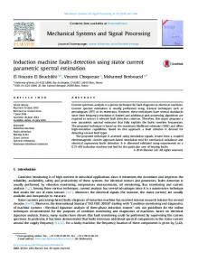
Fig. 1. Four types of rolling-element bearing misalignment [5].
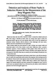
(2) C. Rotor Asymmetry It has been shown that when a rotor asymmetry is present, the air-gap flux density will be perturbed and this perturbation will rotate at shaft speed. The frequencies of the spectral components in the air-gap flux density are given by [2] (3) Fig. 2. Ball-bearing dimensions.
D. Bearings Failure Installation problems are often caused by improperly forcing the bearing onto the shaft or in the housing. This produces physical damage in the form of brinelling or false brinelling of the raceways which leads to premature failure. Misalignment of the bearing, which occurs in the four ways depicted in Fig. 1, is also a common result of defective bearing installation. The relationship of the bearing vibration to the stator current spectra can be determined by remembering that any air-gap eccentricity produces anomalies in the air-gap flux density. Since ball bearings support the rotor, any bearing defect will produce a radial motion between the rotor and stator of the machine. The characteristic frequencies for ball bearings are based upon the bearing dimensions shown in Fig. 2. They are given by [5], [21] (4)
with (5) is the number of balls, the mechanical rotor speed where the bearing pitch diameter, the ball diameter, in hertz, and the contact angle of the balls on the races. III. STATOR CURRENT MONITORING SYSTEM The stator current monitoring system contains the four processing sections illustrated in Fig. 3. A. Sampler The purpose of the sampler is to monitor a single phase of induction motor current. This is accomplished by removing the 50-Hz excitation component through low-pass filtering and
16
IEEE TRANSACTIONS ON POWER ELECTRONICS, VOL. 14, NO. 1, JANUARY 1999
Fig. 3. Block diagram of single-phase stator current monitoring scheme.
sampling the resulting signal. The current flowing in single phase of the induction motor is sensed by a current transformer and sent to a 50-Hz notch filter, where the fundamental component is reduced. The analog signal is then amplified and low-pass filtered. The filtering removes the undesirable highfrequency components that produce aliasing of the sampled signal while the amplification maximizes the use of the analogto-digital (A/D) converter input range. The A/D converter samples the filtered current signal at a predetermined sampling rate that is an integer multiple of 50 Hz. This is continued over a sampling period that is sufficient to achieve the required fast Fourier transform (FFT). B. Preprocessor The preprocessor converts the sampled signal to the frequency domain using an FFT algorithm. The spectrum generated by this transformation includes only the magnitude information about each frequency component. Signal noise that is present in the calculated spectrum is reduced by averaging a predetermined number of generated spectra. This can be accomplished by using either spectra calculated from multiple sample sets or spectra computed from multiple predetermined sections (or windows) of a single large sample set. Because of the frequency range of interest and the desired frequency resolution, several thousand frequency components are generated by the processing section.
Fig. 4. View of the experimental setup.
eliminates those components that provide no useful failure information. The algorithm keeps only those components that are of particular interest because they specify characteristic frequencies in the current spectrum that are known to be coupled to particular motor faults. Since the slip is not constant during normal operation, some of these components are bands in the spectrum where the width is determined by the maximum variation in the slip of the motor. D. Postprocessor
C. Fault Detection Algorithm In order to reduce the large amount of spectral information to a usable level, an algorithm, in fact, a frequency filter,
Since a fault is not a spurious event, but continues to degrade the motor, the postprocessor diagnoses the frequency components and then classifies them (for each specified fault).
BENBOUZID et al.: INDUCTION MOTORS’ FAULTS DETECTION AND LOCALIZATION
17
Fig. 5. Schematic view of the experimental setup.
Fig. 6. Full-loaded motor stator current power spectra.
Fig. 7. Stator current power spectra around 50 Hz.
IV. EXPERIMENTAL RESULTS To verify the generality of the presented considerations, laboratory experiments were performed with an induction motor. The investigated drive system is shown by Figs. 4 and 5. The stator current was sampled with a 1-kHz sampling rate and interfaced to a Pentium PC by a National Instruments data acquisition board. All of the following stator current power spectra are based on a 4096-points FFT.
and 8, more frequency information appears. In fact, one could identify in Fig. 7 eccentricity harmonics at 26 and 74 Hz [see (1)] and rotor asymmetry harmonics at 46 and 54 Hz [see (3)]. In Fig. 8, the shaft speed oscillation harmonic appears clearly at 246 Hz [see (2)]. When accurately analyzing the power spectra, one could notice the absence of obvious bearing failure.
A. Experiment 1
B. Experiment 2
The first experiment involved the drive system driving the full load at 1444 rpm. The power spectra of Fig. 6 represents then, in our case, the supposed healthy motor. However, when zooming the power spectra, as illustrated by Figs. 7
In the second experiment, the stator voltages were unbalanced by adding a 0.2-p.u. resistance to one phase. The power spectra of stator current is then shown by Fig. 9. One should notice the emergence of even harmonics.
18
IEEE TRANSACTIONS ON POWER ELECTRONICS, VOL. 14, NO. 1, JANUARY 1999
Fig. 8. Stator current power spectra for frequencies more than 200 Hz. Fig. 11. Power spectrum of the instantaneous power for a full-loaded motor.
Fig. 9. Stator current power spectra in the case of stator voltage unbalance.
decreasing the distortions of the current waveform and the spectrum noisiness as seen in Figs. 6, 9, and 10. Therefore, in place of the stator current, some authors have proposed the instantaneous power as a medium for the motor signature analysis. It was shown that the amount of information carried by the instantaneous power, which is the product of the supply voltage and motor current, is higher than that deducible from the current alone [22], [23]. Fig. 11 shows clearly the differences with Fig. 7. In fact, all the fault harmonics are translated into the frequency band 0–100 Hz. This constitutes a great advantage because the fault harmonics domain is, in this case, well bounded. However, as illustrated by Fig. 11, the power spectra is still quite noisy so as instantaneous power, at this stage, does not bring important improvement. Therefore, the stator current should be maintained as the main medium for the motor signature analysis. So, instead of using the stator current monitoring system illustrated in Fig. 3, an alternative spectral method allows gathering the preprocessor and the fault detection algorithm. In fact, high-resolution spectral techniques can be used directly from the sampled stator current waveform. VI. HIGH-RESOLUTION SPECTRAL ANALYSIS
Fig. 10.
Stator current power spectra in the case of stator open phase.
C. Experiment 3 The last experiment dealt with the analysis of a single-phase effect corresponding to a stator open phase. Fig. 10 illustrates in this case the power spectra of the stator current. As with the previous remark, we notice the emergence of even harmonics, but with less amplitude. These two cases of electrical-based faults (unbalanced voltage and single-phasing effects) have been quite easily detected, compared to the healthy power spectra of Fig. 6, and classified by the postprocessor, thanks only to the even harmonics amplitude analysis. V. DISCUSSIONS Generally, not denying the diagnostic value of classical spectral analysis techniques, induction motors faults detection via stator current signature analysis could be improved by
The classical spectral estimation techniques which have been used are among the most robust ones, allowing computationally efficient algorithms like FFT. However, a main disadvantage of the classical spectral estimation is the impact of side-lobe leakage due to the inherent windowing of finite data sets. Window weighting allows mitigating the effect of side lobes at the expense of decreasing the spectral resolution which can be no better than the inverse of acquisition time s Hz). (i.e., In order to improve the statistical stability of the spectral estimate, i.e., to minimize the estimate variance, pseudoensemble averaging by segmenting the data was introduced at the price of further decreasing the resolution. So, tradeoffs among stability, resolution, and leakage suppression are necessary. A class of spectral techniques based on an eigenanalysis of the autocorrelation matrix has been promoted in the digital signal processing research literature. They may improve or maintain high resolution without sacrificing as much stability, which allows keeping only the principal spectral components of the signal and decreasing noise influence.
BENBOUZID et al.: INDUCTION MOTORS’ FAULTS DETECTION AND LOCALIZATION
A. Eigenanalysis-Based Frequency Estimators To give the details of these estimators is not the purpose of this paper (see [24] and [25] for details). The principle is just briefly reviewed. The data are assumed to consist of -pure sinusoids in white noise, a suitable model for the stator current (6) is a data, is an additive complex white noise where and and are, respectively, sample of variance amplitude, frequency, and phase of the th sinusoid. These frequency estimation techniques are based on an eigenanalysis which divides the information in the autocor, where is the matrix order, into two relation matrix vector subspaces—one a signal subspace and the other a noise eigenvalues are subspace. The Two well-known eigenanalysis-based frequency estimators have been used: MUSIC and ROOT-MUSIC. It should be noticed that ROOT-MUSIC has been well known for detecting sinusoids in Gaussian white noise. 1) MUltiple SIgnal Classification (MUSIC) Estimator: This estimator is based on the property that the noise subspace of a Toeplitz autocorrelation matrix are oreigenvectors , where thogonal to the signal vectors (7) , the sinusoidal frequencies are estimated as the For peaks of the pseudospectrum given by
(8) , the th sinusoidal frequency Theoretically, when In practice, the obtained spectrum have largest peaks at the principal frequency locations. to in 2) ROOT-MUSIC Estimator: Setting such as the polynomial is (8), (9) is the sum of the matrix The polynomial coefficient elements on the th diagonal. and The ROOT-MUSIC algorithm determines roots of then selects the roots closest to the unit circle, corresponding with These estimators require the determination of the number of frequencies 3) Choice of and : These estimators require the a priori knowledge of the number of frequencies and the autocorrelation matrix order If is unknown in the case of eigenanalysis-based techniques, the number of sinusoids will be chosen as the number
19
of eigenvalues exceeding a given threshold [24]. More generally, a model order selection criterion can be used—the Akaike information criterion for example. With regard to autocorrelation matrix order selection, we would like the dimension of to be large so that the However, doing majority of the eigenvalues are equal to so runs the risk of statistically unstable eigenvalue estimates and high-computational load [25]. B. Experimental Results To verify the generality of the presented estimators, the above algorithms have been implemented to improve induction machines faults detection and localization in the two following experiments. 1) Experiment 1—Distinction of Three Close Frequencies and : Usually, a machine fault modifies the stator current spectrum of the healthy machine by changing the amplitude of some components already present in the spectra. Some faults affect spectral components whose frequencies depend on the p.u. slip related itself to the load. However, for low-slip values, the frequency resolution of the classical spectral estimation technique could not be sufficient for distinguishing close frequencies, for example, the electrical supply frequency with In fact, the classical spectral estimation technique used in Figs. 6 and 10 is the Welch’s periodogram with a Hanning window calculated on the data length (4096 samples). s Hz, The minimal frequency resolution is evaluated by the mainlobe frequency bandwidth of a Fourier transform of the Hanning window. However, it is important to notice that this value is available for close frequencies of the same amplitude. In our case, the resolution will be degraded since the considered frequencies are not of the same , this classical technique amplitudes. In practice, for is unable to distinguish the frequencies and Use of eigenanalysis-based frequency estimators will be useful even if a prefiltering is necessary to select the frequencies under interest. In our case, to select the frequencies to analyze, a solution is to use a pass-band filter centered on For the load at 1444 rpm, stator current power spectrum obtained after filtering is given in Fig. 12. It can be noticed that the three principal spectral components are clear and correspond to the previously defined frequencies (i.e., 46, 50, and 54 Hz) in Fig. 6. In this case, the high-resolution property of the eigenanalysis-based frequency estimators cannot be underscored. 2) Experiment 2—Stator Voltage Unbalance Underscoring: In the case of stator voltage unbalance, one of the principal spectral components modified by the electric fault is the third harmonic of supply frequency (i.e., 150 Hz) whose amplitude increases in a significant way whatever the load. The two principal spectral components of the stator current spectrum are the first and the fifth harmonics (50 and 250 Hz) for the healthy motor (Fig. 6) and the first and third harmonics (50 and 150 Hz) for the stator voltage unbalance (Fig. 9). The MUSIC algorithm has been applied for each case with and , and results are given, respectively, in Figs. 13 and 14. It should be noticed, contrary to Figs. 6 and 9, that
20
IEEE TRANSACTIONS ON POWER ELECTRONICS, VOL. 14, NO. 1, JANUARY 1999
Fig. 12.
Power spectrum after pass-band filter at 1444 rpm.
Fig. 13.
MUSIC frequency estimate for the healthy machine.
Fig. 14.
MUSIC frequency estimate for the stator voltage unbalance.
BENBOUZID et al.: INDUCTION MOTORS’ FAULTS DETECTION AND LOCALIZATION
spectral signatures illustrated by Figs. 13 and 14 can be easily used for the detection and identification of a potential voltage unbalance. The frequency values obtained with the ROOT-MUSIC and are 50.11 and 250.43 Hz estimator for for the healthy motor and 50.08 and 150.22 Hz for the stator voltage unbalance. C. Discussions With regard to these results, MUSIC and ROOT-MUSIC methods allow keeping only the main frequencies without other spectral information. This is a first step to an automated diagnostic system. The main advantages of the high-resolution spectral analysis can be underscored in the last experiments: 1) taking the stator current model into consideration; 2) noise influence reduction; 3) extraction of the useful information (prefiltering and choice of the number of sinusoids). Even if the primary motivation for eigenanalysis-based frequency estimators, i.e., the high-resolution property, has not been underscored in these experiments, this property can be shown for lower slip values. In comparison with the classical spectral analysis techniques, the eigenanalysis-based spectral methods are computationally intensive. The approximate relative computational complexity of MUSIC and ROOT-MUSIC , where is the number of samples, whereas algorithms is [24]. classical spectral technique one is VII. CONCLUSIONS This paper has taken the initial step to investigate the efficiency of current monitoring for diagnostic purposes. The effects of stator current spectrum have been described and the related frequencies determined. In the present investigation, the frequency signature of some asymmetrical motor faults have been well identified using advanced signal processing techniques, such as high-resolution spectral analysis. Experimental results have demonstrated that the stator current high-resolution spectral analysis, proposed as a medium for induction motors faults detection, has definite advantages over the traditionally used FFT spectral analysis, and, more generally, this technique will be useful in all faults modifying main spectral components. Extensive experimental studies are necessary to full assess usefulness of the proposed technique for the preventive maintenance diagnostics and failure prevention in drive systems with induction motors. APPENDIX RATED PARAMETERS OF THE MACHINE UNDER TEST Power Frequency Voltage Current Speed Pole pair
4 50 220/380 15/8.6 1440 2
kW Hz V A rpm
21
ACKNOWLEDGMENT The authors thank A. Berrehilli and N. Farid for setting up the experimental system. The valuable comments made by the reviewers are also acknowledged. REFERENCES [1] J. R. Cameron, W. T. Thomson, and A. B. Dow, “Vibration and current monitoring for detecting airgap eccentricity in large induction motors,” Proc. Inst. Elect. Eng., vol. 133, pt. B, pp. 155–163, May 1986. [2] G. B. Kliman and J. Stein, “Induction motor fault detection via passive current monitoring,” in Proc. 1990 Int. Conf. Electrical Machines, vol. 1, Cambridge, MA, pp. 13–17. , “Methods of motor current signature analysis,” Elec. Mach. [3] Power Syst., vol. 20, pp. 463–474, Sept. 1992. [4] R. R. Schoen, B. K. Lin, T. G. Habetler, J. H. Schlag, and S. Farag, “An unsupervised, on-line system for induction motor fault detection using stator current monitoring,” IEEE Trans. Ind. Applicat., vol. 31, pp. 1280–1286, Nov./Dec. 1995. [5] R. R. Schoen, T. G. Habetler, F. Kamran, and R. G. Bartheld, “Motor bearing damage detection using stator current monitoring,” IEEE Trans. Ind. Applicat., vol. 31, pp. 1274–1279, Nov./Dec. 1995. [6] T. W. S. Chow and G. Fei, “Three phase induction machines asymmetrical faults identification using bispectrum,” IEEE Trans. Energy Conversion, vol. 10, pp. 688–693, Dec. 1995. [7] F. Filippetti, G. Franceschini, C. Tassoni, and P. Vas, “A fuzzy logic approach to on-line induction motor diagnostics based on stator current monitoring,” in Proc. 1995 IEEE Int. Power Tech. Conf., vol. EMD, Stockholm, Sweden, pp. 156–161. [8] J. Penman, M. N. Dey, A. J. Tait, and W. E. Bryan, “Condition monitoring of electrical drives,” Proc. Inst. Elect. Eng., vol. 133, pt. B, pp. 142–148, May 1986. [9] D. J. T. Siyambalapitiya, P. G. McLaren, and P. P. Acarnley, “A rotor condition monitor for squirrel-cage induction machines,” IEEE Trans. Ind. Applicat., vol. 23, pp. 334–340, Mar./Apr. 1987. [10] P. J. Tavner, K. K. Amin, and C. Hargis, “An electrical technique for monitoring induction motor cages,” in Proc. 1987 IEE Int. Conf. Electrical Machines and Drives, London, U.K., pp. 43–46. [11] D. Leith, N. D. Deans, and I. D. Stewart, “Condition monitoring of electrical machines using real-time expert system,” in Proc. 1988 Int. Conf. Electrical Machines, vol. 3, Pisa, Italy, pp. 297–302. [12] P. J. Tavner, “Condition monitoring—The way ahead for large electrical machines,” in Proc. 1989 IEE Int. Conf. Electrical Machines and Drives, London, U.K., pp. 159–162. [13] D. J. T. Siyambalapitiya and P. G. McLaren, “Reliability improvement and economic benefits of on-line monitoring system for large induction machines,” IEEE Trans. Ind. Applicat., vol. 26, pp. 1018–1025, July/Aug. 1990. [14] S. Chen, E. Zhong, and T. A. Lipo, “A new approach to motor condition monitoring in induction motor drives,” IEEE Trans. Ind. Applicat., vol. 30, pp. 905–911, July/Aug. 1994. [15] W. Deleroi, “Broken bars in squirrel cage rotor of an induction motor, Part 1: Description by superimposed fault currents,” (in German), Arch. f¨ur Elektrotechnik, vol. 67, pp. 91–99, 1984. [16] R. Belmans, A. Vandenput, and W. Geysen, “Influence of torsional vibrations on lateral oscillations of induction motors rotors,” IEEE Trans. Power Apparatus Syst., vol. 104, no. 7, pp. 1832–1837, 1985. [17] IAS Motor Reliability Working Group, “Report of large motor reliability survey of industrial and commercial installations, Part I,” IEEE Trans. Ind. Applicat., vol. 21, pp. 853–864, July/Aug. 1985. , “Report of large motor reliability survey of industrial and [18] commercial installations, Part II,” IEEE Trans. Ind. Applicat., vol. 21, pp. 865–872, July/Aug. 1985. [19] , “Report of large motor reliability survey of industrial and commercial installations, Part III,” IEEE Trans. Ind. Applicat., vol. 23, pp. 153–158, Jan./Feb. 1987. [20] A. H. Bonnett and G. C. Soukup, “Cause and analysis of stator and rotor failures in three-phase squirrel-cage induction motors,” IEEE Trans. Ind. Applicat., vol. 28, pp. 921–937, July/Aug. 1992. [21] R. L. Schiltz, “Forcing frequency identification of rolling element bearings,” Int. J. Sound Vibration, pp. 16–19, May 1990. [22] R. Maier, “Protection of squirrel-cage induction motor utilizing instantaneous power and phase information,” IEEE Trans. Ind. Applicat., vol. 28, pp. 376–380, Mar./Apr. 1992. [23] S. F. Legowski, A. H. M. S. Ula, and A. M. Trzynadlowski, “Instantaneous power as a medium for the signature analysis of induction
22
IEEE TRANSACTIONS ON POWER ELECTRONICS, VOL. 14, NO. 1, JANUARY 1999
motors,” IEEE Trans. Ind. Applicat., vol. 32, pp. 904–909, July/Aug. 1996. [24] S. L. Marple, Digital Spectral Analysis with Applications. Englewood Cliffs, NJ: Prentice-Hall, 1987. [25] S. M. Kay, Modern Spectral Estimation. Englewood Cliffs, NJ: Prentice-Hall, 1988.
Mohamed El Hachemi Benbouzid (S’92–M’94) was born in Batna, Algeria, in 1968. He received the B.Sc. degree in electrical engineering in 1990 from the University of Batna, Batna, and the M.Sc. and Ph.D. degrees in electrical and computer engineering in 1991 and 1994, respectively, from the National Polytechnic Institute, Grenoble, France. After graduation, he joined the University of Picardie “Jules Verne,” Amiens, France, where he is an Associate Professor of Electrical and Computer Engineering. His current research interests include electric machines and drives, electromagnetics computational, and electromechanical actuation as well as techniques for energy savings. He is leading a research program on induction machine drives monitoring and diagnostics for the French Picardie Region. He has published more than 40 technical papers including 15 refereed publications in journals. Dr. Benbouzid is a Member of the French Society of Electrical Engineers SEE and is active in PES and IAS-IEEE.
Michelle Vieira was born in Belfort, France, in 1972. She received the B.Sc. degree in telecommunications in 1994 from the University of NancyMetz, France, and the M.Sc. degree in signal processing in 1995 from the University of Nice, Sophia Antipolis, France. She is currently working toward the Ph.D. degree in monitoring and diagnosis of induction motors via signal processing at the University of Nice.
C´eline Theys was born in Paris, France, in 1967. She received the B.Sc., M.Sc., and Ph.D. degrees in electrical engineering and digital signal processing from the University of Nice, Sophia Antipolis, France, in 1989, 1990, and 1993, respectively. She is currently an Associate Professor at the University of Nice. Her research interests include digital signal processing for the detection of abrupt changes and fault diagnosis.