COMBINING CAPACITOR/INDUCTOR AND IDLING ASYNCHRONOUS MOTOR IN DESIGN OF A SYSTEM FOR BALANCE OF A LARGE TWO-PHASE INDUSTRIAL LOAD OVER THREE PHASES. Coyle E., O’Kelly H., Farrell M., Campbell W.J. Dublin Institute of Technology, Kevin Street, Dublin 8, Ireland.
[email protected] Fax: 00-353-1-4024996 Keywords: Phase-Balance, Harmonic Distortion, Idling Motor, Unbalance
Abstract This paper describes the design and implementation of a new solution to power quality problems associated with large unbalanced non-linear loads at fine glass furnace production utilities. Such furnaces use two-phase electricity for reasons of enhanced temperature control and in order to maintain consistency of glass viscosity. A significant risk of power failure is introduced due to this requirement. The furnace load is also non-linear in nature, due to temperature control by electronic power switching. This gives rise to risks associated with high harmonic distortion. A new method in design of filters to alleviate problems associated with this type of load is also described.
1.
Introduction
Over the past decade the manufacture of fine glass products by such companies as Waterford Crystal of Ireland, Stuart Crystal of UK, Swarovski of Austria, Atlantis of Portugal, has become automated, with skills transferred from craft workers to robotic production systems. The process also involves the replacement of the traditional pot furnaces used by the glass blowers, with large industrial electrically heated units having power ratings in the region of 1 MW to 3 MW. These furnaces are constructed using a glass-based refractory brick and the glass is generally kept in a molten state at 1,150 degrees Centigrade by means of resistance heating. To achieve this, a large current is passed through the molten glass. If power to the furnace fails, the contents begin to cool down immediately. As the temperature reduces the glass resistance increases, reducing its ability to absorb power. A point is quickly reached (quarter to half an hour depending on furnace size) where the molten glass fuses with the refractory brick. Once this happens the process becomes irreversible and the whole furnace turns into a solid glass block. The only solution at this point is to break up and remove the glass block and rebuild the entire furnace. Such a failure would result in major rebuild costs together with consequent loss of
production and market. The rebuild cost alone, of a typical 1 Mega-Watt furnace is estimated to be in the region of 12 million Euro. In order to reduce the risk of such a failure, electric glass furnace manufacturers and users have examined and treated weaknesses in the construction and within the electrical supply configuration. One of the major remaining weaknesses is the fact that these furnaces used two-phase electricity for reasons of enhanced current direction control and consistency of glass viscosity. This configuration, if not corrected for, will result in significant unbalance of phase currents and voltages within the plant and on the feeding three-phase utility supply. Two-phase configurations can introduce significant risks of power failure, due to maloperation of critical auxiliary equipment and the furnace itself. The furnace load is also non-linear in nature, due to temperature control by thyristor switching. This gives rise to risks associated with high harmonic distortion, which can result in failure of essential ancillary equipment and indeed of the supply system itself.
2.
Converting Three-Phase to Two-Phase
There are a number of well known methods of distributing a two-phase load across three phases. These include Scott wound transformer, Capacitor/Inductor method, Le Blanc transformer, PWM converter, motor generator. The two most commonly used in the glass industry are Scott wound transformers and capacitor-inductor combinations. 2.1
Scott Transformer Method
Scott wound transformers consist generally of two independent two-phase transformers. A centre tap from the primary of the first (main) transformer is brought out and connected to one pole of the primary of the second (called the teaser transformer). The secondaries of these transformers will produce two voltages in quadrature, which can be arranged to be of equal magnitude. Although originally used to supply two-phase motors form a three-phase supply, they can also be arranged to distribute a two-phase load over three phases. This is achieved by leaving the secondary of the main transformer open, and connecting the two-phase load across
the secondary of the teaser transformer. The result is that the load current is split in the ratio 2:1:1 across the three-phase supply.
values leads to a balanced set of resultant current vectors (shown in black). To achieve this both IL and IC must have the value
A disadvantage of the Scott method is that additional load must be added across two phases to achieve and maintain balance. Further difficulties will arise if the power factors of the Scott transformer and of the added load differ. 2.2
P amps 2V cos 30
Capacitor/Inductor Method where P represents the full load power and V the supply
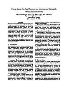
A two-phase resistive load may be converted to three-phase balanced by the connection of an inductor and capacitor between the loaded phases and the unloaded one. Circuit and Phasor diagrams are shown in figures 1 and 2.
T
S
R
system voltage. Both L and C will in this case have equal reactance at 50 Hz. An important point of note is that L and C will form a 50 Hz series tuned circuit across R and S, if T phase is disconnected. Should the T phase become disconnected, this tuned circuit would produce a short circuit between the R and S phases. In practice this situation can arise from fuse failure or loss of phase from the supply source. It can also occur momentarily during the closing or opening of a feeding contactor or circuit-breaker. The latter situation arises due to mechanical time differences in the closing or opening of the individual phase contacts.
3.
Capacitor Inductor Model
Load The main difficulty with past attempts to use Capacitor / Inductor method has been this problem relating to the danger of 50 Hz resonance in the event of the centre phase (T phase in this case) becoming disconnected. Figure 6 shows how this leads to the occurrence of a short circuit between R and S phases.
Figure 1 Capacitor-Inductor balancer
IC
IL XC
T
I load
S
R
I load
XL
S
R Load
IC
IL
Figure 2 Phasor diagram of C-L balancer IC and IL represent the capacitor and inductor currents represents the resistive load current flowing in R and S phases. Appropriate selection of inductor and capacitor
Figure 6 Fifty Hz resonant circuit A laboratory experiment was set up to measure over-current and over-voltage in the event of centre phase loss with a capacitor/inductor balancer.
The experiment involved the use of commercially available capacitors and inductors of the type proposed for the balancer. The capacitors were connected in series-parallel configurations to allow for high voltage during the test. The objective was to measure the peak and RMS capacitor voltage after disconnection of the T phase. From the measurements it was concluded that a peak voltage of 2.2 kV and an RMS of 1.053 kV would be reached. It was concluded that the removal of the central phase would result in the capacitor being over-stressed, with the consequent possibility of violent failure. It was therefore deemed necessary to take account of this fact in the design of any balancer built using capacitor / inductor combinations. It was decided to introduce impedance between the centre phase (T phase) and the other two phases in order to limit the capacitor voltage in the case of T phase becoming disconnected. This was achieved by connecting idling asynchronous motors in such a way that the balancer would not function unless these were running. Two motors were installed for this purpose. Only one was required, the other was to act as a standby.
The approach illustrated here is based on the addition of suitable three-phase negative sequence currents to that of a two-phase load, in order to create a set of balanced threephase currents. This solution is best described using the method of Kemp [2], for the derivation of positive and negative phase sequence components.
5
Kemp Method
Kemp described a graphical method of deriving the positive and negative phase sequence components of a three-phase system of voltages or currents [5]. This method, outlined here, is more suitable for explaining the operation of the balancer.
IN
R
S
TII T T
The motors used were ABB catalogue number N2BA 132 315 SMB, rated 132 kW at 400 volt with 95.3% efficiency, and at 0.80 power factor. For these motors, manufacturers test data indicated that Z1 = 0.66 + j1.83 ohms Z2 = 0.031 + j0.15 ohms
S
R
Z1 and Z2 are the positive and negative phase sequence impedances of the motor running under no-load. Rated current is 254 amps at 0.85 power factor The voltage level with motor connected and T phase removed was then calculated. It was concluded that in the worst case situation a capacitor voltage of 887 volts could be reached. This was within the short term withstand capability of the capacitor, and would also cause the main balancer circuitbreaker to trip on over-voltage, after a short period.
T
TI S IP
R
Figure 3 Kemp construction for unbalance load
4
Balancer comprising Capacitor/Inductor with Idling Motor
After further investigation it was concluded that the idling motor could contribute balancing currents if it was supplied from a deliberately unbalanced voltage source. The objective was to reverse the process developed by Campbell [1] who described a method by which a single-phase supply can be converted to a three-phase supply using an asynchronous motor.
Referring to Figure 3; consider a three-phase system of unbalance currents (shown in blue). Based on the RS phase line, two equilateral triangles are drawn and the extremities marked as TI and TII (shown dotted). Join TI and TII to T. Kemp proved the vector TI T ÷ 3 represents the magnitude and direction of the T component of a balanced positive phase sequence set of currents (shown in red). The vector TII T ÷ 3 represents in magnitude and direction the T component of a
balanced negative phase sequence set of currents (shown in green). This argument holds equally well for a two-phase resistive current IS flowing between two phases (say R and S phases). This current is equivalent to a three-phase system, with IR flowing in R, IS ( = – IR) flowing in S phase, and zero current flowing in T phase. Figure 4 demonstrates, using the Kemp construction, the resolution of this two-phase current into its positive and negative phase sequence three-phase components.
TII
S
6.
Prototype Design
A prototype unit was built to balance a test furnace. This was installed on a trial furnace located at the Waterford Crystal factory in Butlerstown, Dungarvan. This furnace had a twophase heating load of 30kW, connected across two phases of a 400-volt three-phase supply. The unit comprised two 7.5 kW pilot-motors (arranged to rotate in opposite directions on a common mounting frame) and five capacitor/inductor steps (5 kVAr capacitors and 203 mH, 64 ohm inductors). Utilising two motors enabled a reduction of noise and vibration, by cancellation. The motors were supplied with and unbalanced voltage by using auto-transformers connected as shown in figure 5.
Negative TSR
ψ
ISP
R
IRP
A
T
IS
IR
(1-A)ISP A.ISP IS
S
ψ
B – B.IRP
(1+B)IRP
IR
R Figure 5 Current flow in the auto-transformer
Positive TRS
TI Figure 4 Kemp construction for two-phase load
IS and IR represent the full load current flowing in R and S phases. If a negative phase sequence current equal and opposite to IN is injected into the three-phase system, the resultant seen by the supply system is the balanced threephase positive phase sequence component of IS and IR. Since
I = I1 + I 2
For the prototype unit, design calculations realised optimum value of A-tap and B-tap transformer values of 0.2125 V and 0.0975 V respectively, maximum pilot current 9.98 A, maximum capacitor voltage with T-phase removed 488 V. The balancer was wired so that the T phase connection was always maintained between the capacitor steps and the pilot motors, once the balance was switched on. This was to ensure that appropriate impedance always remained in place across the capacitors, so limiting voltage rise. The capacitor / inductor steps were controlled to follow the load profile thus maintain optimum balance.
It follows that I1 = I – I2 From this we can deduce that if a current equal and opposite to the negative phase sequence component, is added to the unbalanced system, the resultant will be a set of balanced positive phase sequence currents.
7.
Production Model
Following the successful operation of the test balancer, a fullscale model of the phase balancer was subsequently constructed and installed at the Waterford Crystal plant, Kilbarry, Waterford City. The furnace consists of two main sections; firstly the tank where the solid glass fillings are heated to a molten state; secondly a long section of molten
glass channels called the Foreheart. From the latter section glass blowers, and robotic production machinery, extract molten glass for moulding into finished product. The high level of load unbalance was causing reliability problems for production and auxiliary motive power equipment connected to the furnace. The control circuitry of the balancer was set to monitor furnace two phase load current. The motor balancer was sized to maintain balance for furnace base load while the capacitor / inductor steps were to follow load variation. The latter were controlled by load current sensing relays set to the appropriate value for each step. The control algorithm was optimised so as to ensure voltage unbalance did not exceed 1%.
For practical design considerations, a balanced filter layout topology was implemented. The bank designed consisted of 3rd, 5th , 7th and 11th tuned branches, each consisting of three steps and controlled by a power factor controller. Power factor control was possible because of the displacement power factor resulting from the thyristor phase angle control of the heating circuits. This power factor was shown by measurement to have a near linear relationship with harmonic current generated by the load.
References [1]
[2]
8.
Results
[3] [4]
By connecting the balancer to the furnace, the level of voltage unbalance was reduced from a negative phase sequence voltage of 2.94 percent to 0.87 percent. The latter value was largely due to system unbalance at the point of connection. By reaching a value lower than 1% the IEC conditions for full load running of motors [4] were established.
9.
Harmonic Distortion Issues
Under European Supply Quality Standard EN50160 [5] limits are set for the maximum voltage unbalance and harmonic distortion, which may appear at the point of common coupling between a customer and an electrical utility. Electronic load control such as by thyristor, can introduce harmonic distortion and other power quality problems, which must be addressed. Distortion measurements were carried out after the furnace was running and the voltage distortion levels were found to be above G5/4 planning levels [6]. As these levels are selected to minimise the possibility of problems for connected load; it was decided that the measured levels should be reduced by the application of suitably designed passive filters. It was decided to design a passive filter bank to absorb the harmonic currents generated by the thyristor load. A software programme was designed enabling the input of maximum currents generated at 3rd, 5th, 7th , 9th ,11th , 13th , 17th , and 19th . The program was written around standard commercially available capacitor power and voltage ratings. The program allows the dimensioning of the filter bank components taking account of voltage, current, harmonic and thermal limitations.
[5]
[6]
W.J. Campbell, ‘Improvements in and Relating to Rotary Phase Converters’. U.K. Patents no. 160 4921, Irish Patent no. 44626, 1971. P. Kemp, ‘A.C. Current Electrical Engineering’, Macmillan, 1963. M. Heathcoat, ‘J & P Transformer Book 12th edition’, Newnes, 1998. IEC, Document 60034-1, ‘Rotating Electrical Machines part 1: Rating and Performance, revision 3’ 1969. National Standards Authority, EuroNorm standard 50160, ‘Voltage Characteristics of Electricity Supplies by Public Distribution Systems’, 1995. Electricity Association UK, Engineering Recommendation G5/4, ‘Planning Levels for Harmonic Voltage Distortion and Connection of Non-Linear Equipment to Transmission Systems and Distribution Networks’, 2001.