Influence of Capacitive and Inductive Loads on the Detectability of Arc Faults Peter Müller
Stefan Tenbohlen
Michael Anheuser
Siemens AG, Germany
[email protected] [email protected]
[email protected] [email protected]
Abstract—In this paper, the influences of capacitive and inductive loads on low current arc faults in low voltage switchgear are evaluated. Measurements show, that especially inductive loads have an influence on the frequency spectra of an arc. Several parameters of influence on the arc current could be characterized. It could be shown, that the chance to detect an arc in a grid with several different connected loads depends on the location of the arc and the influence of all loads on the current shape. Keywords- arc fault, switchgear, arc detection, low voltage, capacitive, inductive, load, load current, fourier analysis
I.
Reinhard Maier
Universität Stuttgart, Germany
INTRODUCTION
Most of the commonly used protection devices are based on over-current evaluation. Although already investigated for many years, it is therefore still very difficult to detect low current arcing events. Protection devices are not sensitive enough to recognize arc currents in the range of rated current of the switchgear [1]. To be able to detect these kinds of arc faults, it is necessary to be able to distinguish between an arcing event and nonhazardous load currents which naturally are within the rated current range of the switchgear. Unlike most common loads, an arc has a special current characteristic. However, loads with high capacitance or inductance, such as rotating machinery, have a high influence on the shape of the current. Therefore, they may influence the characteristic current shape of an arc and reduce detectability. Several different protection concepts focus on different characteristic effects of arc faults. Some try to detect an arc due to its secondary physical effects such as light, noise and heat [2, 3]. Therefore, sensors in the enclosure of the switchgear measure arc parameters and try to identify possibly hazardous conditions. The most common approach is current measuring. Using current as a fault indicator, it is possible to detect short circuits which generate an over current several times higher than the rated current of the switchgear. Circuit breakers and fuses are then able to interrupt the arc current. However, for low current arc faults, these protection devices are not working. Since low current arc faults can be in the range of the rated current of the switchgear, the protection devices won’t recognize them.
A burning arc is part of the current path and therefore influences the current shape due to its characteristic physical effects [4, 5]. Knowing these arc characteristics, it is possible to distinguish an arc from common loads [6]. However, in most applications, especially in switchgear, the overall current consists of many different load currents. For parallel arc fault protection, differential protection devices measure the every ingoing and outgoing current of the switchgear and are able to detect current flow due to an arc fault. This kind of protection is quite reliable but also expensive for switchgears with many outgoing cables. Therefore, in most cases the current is only measured in the circuit breaker at the grid connected side of the switchgear. The current probes in the switch measure the sum of all connected load currents. The arc current is a part of the measured total current and an arc fault detection devices using only the measured current in the circuit breaker has to be able to detect an arc although the arc current is not measured exclusively. Depending on the type and on the location of the arc fault, there are different problems to be solved in arc detection. Parallel and series arc faults are naturally very different in case of possible location within a switchgear. Parallel arc faults are always in parallel to all other connected loads and the influence of fault location on its current shape is small. Detectability of series arc faults on the other hand depends very much on the location of the fault. A series arc fault is directly influenced by all the connected loads in series to the fault location. Since inductive and capacitive loads have a high influence in the current shape, every uncompensated load influences the shape of an arc current. The aim of this paper is to show the influence of the arc location in a low voltage switchgear and the influence of connected loads on the arc current and therefore on the detectability of an arc fault. II.
SUM OF CURRENTS IN A SWITCHGEAR
A switchgear’s main purpose is to distribute electrical power to different connected loads. Therefore, the switchgears physical dimensions are defined according to the amount of connected loads. The maximum of assumed current leads to the maximum of allowed current in normal operation conditions and therefore the rated current of the switchgear IN.
978-1-61284-651-4/11/$26.00 ©2011 IEEE
According to IN the circuit breaker is selected and all switchgear components are dimensioned to carry this current. Currents higher than the rated current mightt be tolerated for a short time, but are regarded as not allowed operation condition on a larger time scale. The thermal protecttion of the circuit breaker protects the switchgear by disconnnecting the power supply from the grid. Low current arc faults are faults within the rated current of the switchgear. Therefore, the common protecttion devices can’t detect them, because they do not neceessarily result in overcurrent. One of the main differences bettween a series and a parallel arc fault is the possible fault curreent. A parallel arc fault is a potential short circuit, because its current is not limited. The current of a series arc fault is always limited by the loads in series to the fault position. Two T rules can be defined out of this: A parallel arc fault is an additional load in n the switchgear. The current path has not existed before the arc a fault occurred. The fault current is added to the overaall current of the switchgear. Depending on the reason for thhe parallel arc, the amplitude of the arc current may vary and coould even result in a short circuit current. It may therefore be detected easier, because the overall current can exceed the raated current of the switchgear. A series arc fault is an additional resistan nce in an existing current path. Because of the resistance of the arc itsellf and the power consumption, the series arc fault reduces the t current to the connected load. The overall current in the t switchgear is reduced due to the arc resistance. The current c at the arc position can only become smaller, but neverr higher than at the same point without arc. Also, as soon as the load in series to the arc is switched off, the arc also extinguiishes. A series arc fault may have a limited arc current, but it iss also a failure that has to be detected as early as possible. A. Relation of arc current to overall currentt in the switchgear Whether an arc can be easily detected or noot depends a lot on the ratio between arc current and the overrall current in the switchgear. If the arc current is small in relaation to the current of all connected loads, the characteristics inndicating an arc in the time and frequency domain [6] may be too small to be used as a secure fault indicator.. Since the arc current and therefore the peculiarity of the arc charracteristics is not predictable, the trigger level of an arc fault protection device must be high enough to avoid false trippingg. If for example a the current level at a certain frequency speectra is used as an arc indicator, the trigger for declaring an arc fault has to be set to a certain level. This level can be foundd by doing a zero measurement during the installation of the protection device. mple, two times the The trigger level can then be set to, for exam measured level without an arc fault. To distinguish an arc from normal load byy its characteristic frequencies, it is also important how “ccontaminated” the current signal already is. If there are severaal loads connected that cause a high level of harmonicss and disturbing frequencies, the frequencies caused by thee arc may perish between the others. For series arcs, the ratio r between arc
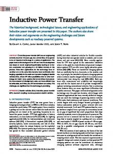
current and overall current Iarc / Isum does not change because the arc position is stable and thhe arc current is always limited by the connected load. For paarallel arcs, the ratio could get better, if the arc is moving orr the arc resistivity gets lower. The chance for a protection devvice to detect the arc gets better. The current of the arc is also innfluenced by the position of the arc fault within the switchgeaar. Is has a direct influence on detectability and will be discussed in the next section. B. Influence of arc fault positioon on detectability The detectability of a series arc fault is influenced by its position within the switchgearr. The closer the fault is to the circuit breaker and thereforee to the current measurement device, the more current has too pass the arc. The strongest arc will occur between the circuitt breaker and the first outgoing line (number 1 in figure 1). The T current of every connected load flows through the fault. Iff the arc extinguishes, the whole current of the switchgear is zero z until re-ignition. Measured current in the protection devvice consists only of the arc current. The arc characteristiics in the time and frequency domain defined in [6], such as a the current gap after current zero, can be used to indicate ann arc. The further away the arc fauult is from the location of the current probe and the more ouutgoing lines are between these two points, the smaller it gets thhe ratio between arc current and overall switchgear current. Morre and more undisturbed current is added to the decreasing arc current. c It gets more difficult for a current characteristic based protection device to detect an arc. If a series arc fault occurs in a connection between busbar and load, the arc current only consiists of the load current (number 2). Depending on the amplitudde of the load current, it can be very difficult to detect this kinnd of fault. On the other hand, the smaller the current over the arc is, the less dangerous is it for the switchgear. Tests showeed [6] that a series arc fault with less than 100 A arc current willl most likely extinguish by itself before melting enough coppper to seriously damage the switchgear. Since a parallel arc is not inflluenced by connected loads, its arc current does not primarilyy depend on its position within the switchgear. It is alwayss in parallel to all the other connected loads (number 3). The arc current is only limited by the arc impedance and the arc a causing event or object.
Figure 1: Circuit of a switchgear wiith connected loads (XL, XL2, XL3, …). 1: Series arc fault in the busbarr between circuit breaker and first connected load. 2: Series arc in a branch connecting a load with the busbar. 3: Parallel arc fault betweeen phase and ground. The arc is in parallel to the power supply, indepeendent on the fault position within the switchgear.
Whenever a protection device is only measuuring the current at the feeding side of the switchgear, the faultt current is only a part of the total current and the ratio beetween these two currents depends on several terms, such as thhe kind of arc fault and the location of the fault within the switcchgear. To prevent false tripping, the difference between characcteristic conditions indicating an arc fault and normal operation conditions should be significant enough. On the other hand, thhe smaller the arc current in relation to the overall current, the smaller the difference between characteristic numbers indicating normal operation and operation with an arc burning in the switchgear. Therefore, if the threshold level indicating an arc is selected too high, an arc with lower current amplituudes might not be detected. If an arc has to be detection by only usingg characteristics in the measured current, these two facts have to be balanced. Either risking a false tripping but beiing sensitive, or preventing false tripping by reducing sensiibility for low arc currents. III.
Figure 2: Circuit for the generation of an arc with resistive load in series. The load consisted of several ohmicc loads with 800 mΩ total resistance. Current was measured between the switch s and the arc.
The measured current (figgure 3) shows specific arc characteristics, such as the arc extinguishing after current zero and the steep current rise after reaching r the restrike voltage.
INFLUENCE OF INDUCTIVE LOADS
Inductive loads such as motors or other rotatting machinery are very common loads. Depending on the induuctance, they cause an angular phase shift in the current. Duue to current zero crossing, arcs with sinusoidal current extingguish and have to reignite. Therefore, the voltage has to rise until it is high enough to reach the restrike voltage of the arrc gap between the electrodes. Several papers [7, 8, 9] state thaat the difference of phase between the sinusoidal voltage and cuurrent can prevent arc extinguishing after current zero. Due to the inductance the voltage reaches zero before the current annd climbs already again till current reaches zero. After the arrc current crossed zero, the voltage may have already reacched the restrike magnitude of the plasma and prevent a current gap due to arc extinguishing. The arc current is riding righht through current zero. If an arc doesn’t extinguish long enough aft fter current zero, it is very difficult to detect it. The re-ignition process p is a major characteristic of an arc that separates it from m most other loads. It is therefore essential to know, whether an inductive load can influence arc characteristics in the time and frequency domain enough to make arc detection difficult. To test the influence of inductive loads on arc a characteristics, arc currents of resistive and inductive circuiits were measured and compared. To simulate inductive loads, several coils were used. Their total inductance is up to 0.67 mH H. Other tests were done with a section of a transformer coil with w inductance of 7.2 mH. Tests results showed that it was not possible to generate strong series arcs with this coil. The T reactance was too high to allow enough current flow for a serious s arc. First tests were made with a purely resistivee circuit as seen in figure 3 to generate a reference current profille.
Figure 3: Arc current with resistive load. l
Looking at the frequency specctra of the arc current (in figure 4), a broadband increase, espeecially in the area between 150 and 1000 Hz, is visible. Alsoo there are increased frequency amplitudes in the range of 1 to 5 kHz. This is caused by the reignition of the arc and the ressulting rapid increase in current [see figure 3]. These charaacteristic arc parameters were already discussed in other papeers [5, 6].
Figure 4: Frequency spectra of an arrc current with purely resistive load.
The resistive load (R) in figure 2 is then repllaced by coils (XL) to simulate an inductive load. The same tesst is repeated with the same conditions to get a similar curvve, this time with inductive load.
Figure 5: Circuit for testing the influence of ind ductive loads on arc characteristics. The arc fault is in series to a 0.67 mH m coil. Current was measured between the switch and the arc.
Due to the low resistivity of the 0.67 mH coil, c the current is higher that with the resistive load. The meaasured current also showes characteristic arc fault features. Hoowever, due to the phase shift, the restrike voltage is reached faster f after current zero and the current gap is therefore much smaller s (see figure 6). It is also visible, that the arc does not extiinguish after every current zero. If there is enough hot plasma between the electrodes, which reduces restrike voltaage, the arc can continue to burn and doesn’t interrupt currennt flow.
Figure 7: Frequency spectra of a series arc current, limited by an inductive load. After re-ignition of the t arc, the current rise is slowed due to the inductor. This reduces high frequency components in the spectra.
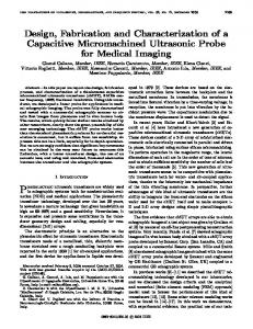
Comparing both frequency speectra, it shows that the inductive load reduces high frequency coomponents in the spectra above 1.5 kHz (see figure 8). Althouggh the current is higher with the inductive load due to the low wer resistivity of the coils, the shape of the frequency spectraa in the lower frequency area is very similar to an ohmic load.
1.5 kHz
Figure 6: Current of a series arc fault with an indu uctive load. The shape of the curve is similar to the arc with ohmic load bu ut the gaps in current after crossing zero are shorter or not existing.
In the frequency spectra (figure 7), the induuctive load reduces high frequency components. The coil woorks similar to a frequency filter with a low pass charactteristic. It is not possible for the current to rise after re-ignitiion as fast as with an ohmic load.
10 kHz
Figure 8: The comparison of frequen ncy spectra of figures 4 and 7 shows a large difference between the amplitu udes in the range of 1.5 to 10 kHz. The inductive load reduces high frequenccy components in the arc current.
IV. CAPACITIVE DETECTION
LOADS
A AND
SELECTIVE
ARC
FAULT
Highly capacitive loads are more seldom than ohmic or inductive loads. Capacities in an electrical installation mainly consist of the capacities of cables, c fluorescent lamps with capacitive compensation and input filters for example in power supply units. Highly inductive i loads may also have compensation capacitors to minnimize reactive current. Capacitive loads and the capacitance of the electrical installation have an influence on the current shape of an arc.
The arc will be in parallel to the capacities, since s the current of a capacitive load will most likely not be highh enough to ignite a series arc fault (see figure 9). The current through the arc is the sum of the current supplied by the grrid and the stored energy in capacities in the electrical installlation. Especially during re-ignition the high frequency compponents of the arc current can be supplied by capacitors.
Figure 11: Measurement setup for testing the influence of capacities on the arc current.
The test results showed only minimal m difference between the two measured current curves in i the time domain, which was expected (figure 12). Figure 9: Influence of capacitor Ci on a parallel arc fault. High frequency components of the arc powered by the energyy stored in all the capacitances in parallel to the arc. The arc current iss I1 +I2.
A series arc fault is also affected by caapacitances in the electrical installation. Although the arc currrent is limited by the connected load, capacities in the installaation also provide stored energy for the arc. Whether the cappacitances have an influence on the measured arc current depennds on the location of the failure in relation to the point of currrent measurement. If the current is only measured in the circuiit breaker close to the power supply, every capacitor in thee installation will reduce high frequency components provided by the grid and therefore measured by the protection device (see figure 10).
Figure 12: Current curve of an arrc fault with ohmic load. Curve one (black) is measured in the switchgeaar. Curve two (gray) is measured right at the arc which was generated on a test bench according to [11]. Between µ is connected between phase and the two points a capacitor of 20 µF ground (see figure 9).
Figure 10: Current flow of a series arc fault. C1 and d C2 are the capacities of a cable or connected loads with high capacitiess. The arc current is fueled by the connected grid and the capacities. The high frequency components of the arc are supported by all capacities in the installation.
To test the influence of a capacitor on the detectability d of an arc, a measurement setup according to figurre 11 is used. The current is measured at two points in the grrid. Current probe one is installed close to the switchgear. Thee distance between switchgear and test setup is approximately 15 1 meters. Current probe two is positioned close to the arc fault fa electrodes. A capacitor C of 20 µF is connected in the midddle between probe one and probe two as shown in figure 11. Current C probe two measures the total arc current. It has two coomponents, I1 and IC. I1 is supplied by the power grid measurred by probe one. The other component IC, mainly consisting of high frequency components, is supplied by the capacitor.
The more interesting difference should be visible in the frequency domain. However,, the differences between the frequency spectra of probe onne and two are only minimal. There is a slight difference in i the range of 5 kHz, which should be the frequencies causeed by re-ignition. There is also a slight damping of the frequencies above 50 kHz. However, the used current probes are only designed for frequencies up to 200 kHz. Frequencies above thhis level could not be measured which explains the drop of the amplitude at the far right of the diagram.
fault will reduces higgh frequency components much more. Further investiggations have to be made to get a better understanding of o this effect. • The position of the arc fault has a major effect on the ratio between arc current and overall current Iarc / Isum. The closer this ratio is i to one, the more defined are the characteristic arc frequencies in relation to other frequencies caused byy normal load. The detectability of arc faults in a switchgear depends on the kind of arc fault, the contaminaation of the current spectra with harmonic components and thee capacitance and inductance of the connected loads. Combinning these conditions with the huge variety of possible fields of applications for switchgears, it shows once again, that the deetection of low current arc faults is a difficult task to undertake.
Figure 13: Frequency spectra of currents measurred with probes one (gray) and two (black) according to measurementt setup in figure 11. There are only slightly damped amplitudes in thee area of 5 kHz and above 50 kHz. Probes are limited to 200 kHz, which h explains the drop in amplitude at the far right of the spectra.
Further investigations should be made and a other current probes are recommended. Because the arrc is a non-linear resistance, it is very difficult to calculate thee cutoff frequency of the filter formed by the capacitor and thhe combination of arc resistivity and ohmic load. V.
CONCLUSIONS
The purpose of this paper is, to show the innfluence of the arc fault position within the switchgear and the effect e of inductive and capacitive loads on the current characteristics of series and parallel low current arc faults. Arc currents with w inductive and capacitive loads were measured and comparred to arc currents with ohmic loads. • Inductive loads influence the arc characteristics of series arc faults, both in the tim me and frequency domain. In the time domain, the tim me till re-ignition is reduced or the arc doesn’t extinguuish at all. In the frequency domain, the amplitudes of o high frequencies are considerably reduced. Howeverr, the influence on lover frequencies (below 1 kHz) is small. s • Capacitive loads are expected to havve an effect on the arc current as well. However, testts showed only a minor influence. It is expectedd that capacitors between the point of current measurrement and the arc
REFERENCES [1]
G. D. Gregory and G. W. Scott, “The Arc-Fault Circuit Interrupter: An Emerging Product”, IEEE Transsactions on Industry Applications, Vol. 34, No.5, Sept/Oct 1998 [2] X. Zhou, J. Hastings and T. Schhoepf, “Detection of Glowing Contacts Employing Acoustic Sensing Technology”, T Proceedings of the 24th ICEC Conference, Saint Malo, Frrance, 2008 [3] T. Sidhu, G. Sagoo and M. Sachddev, “Multisensor Secondary Device for Detection of Low-Level Arcing Faults in Metal-Clad MCC Switchgear Panel”, IEEE Transactions on Poower Delovery, Vol. 17, No. 1, January 2002 [4] W. Rieder “Plasma and arc”, Vieeweg Verlag, Germany, 1967 [5] C. E. Restrepo “Arc fault detecction and discrimination methods”, 53rd HOLM Conference, Pittsburgh PA, 2007 M M. Anheuser, „Characteristics of [6] P. Müller, S. Tenbohlen, R. Maier, Series and Parallel Low Current Arc Faults in the Time and Frequency Domain”, 25th ICEC and 56th IEEE Holm Conference on Electrical Contacts, Charleston, SC 2010 The Historical Evolution of Arcing-Fault [7] T. Gammon and J. Matthews, “T Models for Low-Voltage System ms”, Industrial and Commercial Power Systems Technical Conference, IEEE I 1999 [8] Underwritors Laboratories Inc. “Report “ on Arc-Fault Detection Circuit Breakers” for the National Electrrical Manufacturers Association, 1996 [9] M. Dankert, J. Meyer, P. Scchegner, M. Anheuser, „Dreiphasiges phänomenologisches Störlichtboogenmodell zur Berechnung der Stromund Spannungsverläufe“ (three-pphase arc fault model for the calculation of current and voltage curvves) 20th Albert-Keil-Kontaktsemiar, Karlsruhe 2009, VDE-Fachberichht 65 [10] P. Mueller, S. Tenbohlen, R. Maier, M. Anheuser “Artificial low current arc faults for pattern recognitionn in low voltage switchgear“, 55th Holm Conference, Vancouver BC, 20099