3rd International Conference on Management, Economics and Social Sciences (ICMESS'2013) January 8-9, 2013 Kuala Lumpur (Malaysia)
Influence of Die Elements Shapes on Process Parameters in Multi-Point Sheet Metal Forming Process Abdulkareem Jalil Kadhim and Mostafa Imad Abbas
Papazian et al. [4,5] developed a reconfigurable discrete die and a closed-loop shape control system for stretch forming sheet-metal parts for aircraft. The surface of the die was made up of the hemispherical ends of individual pins of square cross-section. The position of the ends could be adjusted by a servo system. The full-scale tool working space was (1800mm×1200mm), and contained 2688 pins. Zhong Yi Cai [6] applies an integrated method, through which the digitizeddie geometry can be directly generated from the measured data of a desired part. Jiang Dan etal [7] apply the reverse engineering as an approach for constructing a CAD model from a physical part through dimensional measurement and surface model. anew strategy for direct generation of die shapes from digitized points with spring back compensation is presented in his paper. Viore Paunoiu et al [8] developed a method for die – punch geometry configuration using Matlab program. The theoretical analysis is applied to the simulation of the doubly curved thin steel plate deformation using finite element method. Seong-Chan Heo et al [9] carry out, a design and fabrication of a flexible forming die for the purpose of manufacturing a prototype of curved plate block for hull structure used in shipbuilding industry. Software for process configuration and punch control were developed to operate the novel flexible forming machine. Liu Chunguo[10] analyzed the deformation mechanism of the multi-point dieless forming and positioning technology with commercial FEM codes. The forming defects such as dimpling and springback in forming were investigated and the preventing measures were proposed
Abstract- Multi-point sheet metal forming (MPSMF) technology is a flexible forming method, used to manufacture rapidly and economically, a three dimensional sheet metal parts. In (MPSMF), the conventional forming (stamping) dies are replaced by a pair of matrices of punches with various end shapes, by controlling the height of each punch, the ends of punches are approximated to a continuous surface of die which eliminates the need to the traditional fixed shape stamping die, this would allow a manufacturer to have a single die to manufacture many parts of varying shapes. In this paper, Bezier technique was used to represent the final product shape (die configuration). Finite element simulation for sheet metal was performed to investigate the influence of die elements (pins) number and head shapes on the stress distribution, shape accuracy (dimpling) and uniformity of the product. Keywords--Multipoint reconfigurable dies. I.
die,
CAD,
Bezier
surfaces,
INTRODUCTION
ECONFIGURABLE multipoint sheet metal forming (MPSMF) is a flexible manufacturing technology which assures the production a variety of three dimensional sheet metal parts with low costs in comparison with the using of the solid dies. The main characteristic of the Multi-Point Forming (MPF) technology is that it employs two sets of adjustable punch matrices called Punch Element Group (PEG). Each punch element in matrix can be manually or numerically controlled to adjust its height for shaping two discrete 3D tool surfaces. In comparison with conventional solid die forming, MPF is a flexible, multipurpose die, and the tremendous cost and long time in manufacturing solid dies can be eliminated. Several designs of reconfigurable forming dies have been developed in stretch forming, deep drawing and stamping operations. In stretch forming, Hardt et al [1,2,3] had carried out an extensive research work dealing with the concepts of discrete surface tooling
R
II. MULTI-POINT FORMING PRINCIPLES In MPF, the solid stamping dies are replaced by two sets of reconfigurable (element or pin groups), as shown in Fig.1 [11]. Each element can be numerically controlled to its desired height to approximate a continuous 3D tooling shape. So, as a universal tool, the upper and lower element groups are applied in the forming of sheet metal to replace solid dies. In MPF operation, each element’s height can be adjusted rapidly. Before forming, the two element groups are set to the desired shapes according to the CAD data. There is no
Abdulkareem Jalil Kadhim and Mostafa Imad Abbas are with Babylon University –Iraq. Email:
[email protected]
145
3rd International Conference on Management, Economics and Social Sciences (ICMESS'2013) January 8-9, 2013 Kuala Lumpur (Malaysia) n
ny
x ∑j=0 Bnx,i (t x ) 𝐵𝑛𝑦,𝑗 �𝑡𝑦 �𝑃𝑖𝑗 P�t x , t y � = ∑i=0
relative movement between adjacent elements during forming.
0 ≤ t x ,t y ≤ 1
Similar to Bezier curves the first and the last points lie on the edge of a Bezier surface. This surface is controlled by 16 control points. The previous mathematical formulation of Bezier techniques have been implemented and integrated with MATLAB software to generate the interior data to represent the curves and surfaces. A simple Bezier surface is shown in Fig 2.
Fig. 1 Apparatus for multipoint forming [11]
The functions of upper and lower element groups are the same as solid dies. This representative method is defined as multi-point die forming (MPDF). While in another method, all elements are not adjusted in advance but kept at the same height. During forming, they are controlled to reach desired heights with appropriate speeds; the sheet metal which is clamped between the upper and lower element groups is forced to generate plastic deformation.
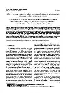
Fig 2. Bezier Surface as an extension of Bezier curve IV. PUNCH (PIN) TIP CONFIGURATION In flexible forming process, contact between blank material and die is dominated by point-to-surface contact unlike to conventional die forming in which surface-to surface contact occurs. Therefore, many pin end configuration were investigated to cover various contact angles at the contact points and show the various product quality. In this research three types of punch tip shape were investigated i.e hemisphere, partial hemisphere or hemi-ellipsoid and flat edges as shown in Fig.3.
III. SURFACE MODELING In multi-point forming, the surface configuration of the required product should be determined, that is mean all the surface points' coordinates should be measured (reverse engineering) or calculated theoretically. The first step is to choose the surface with a predetermined equation which can be manipulated. In this paper Bezier surface was selected to represent the product configuration .with the aid of MATLAB program which based on its capabilities, allow obtaining a mesh with points uniformly distributed, this surfaces can be represented and all surface points can be calculated to determine the pin position for the deformation of the blank. A- Bezier curve A Bezier curve is a parametric curve that uses the Bernstein polynomials as basis. A Bezier curve of degree n (order n + 1) is represented by [12]: P(t) = ∑ni=0 b i B i,n (t)
0≤ t ≤1
R
B i,n (t) =�𝑛𝑖� ti (1 - t)n-i
𝑤ℎ𝑒𝑟𝑒
i = 0 ,…., n. 𝑛!
�𝑛𝑖� = 𝑖!(𝑛−𝑖)!
Fig.3 types of pin end shapes
P(t) = (x(t),y(t)) x(t) =1× x o × t0(1 – t)3+3× x 1 × t1 (1 – t)2+ 3× x 2 × t2(1 – t)1 + 1× x 3 × t3 (1 – t)0 y(t) = 1× y o × t0(1 –t)3 + 3× y 1 × t1 (1 –t)2 + 3× y 2 × t2(1 – t)1+ 1× y 3 × t3 (1 – t)0
V- NUMERICAL SIMULATION In this paper, a commercial FE code (ANSYS 11) is used to simulate the multi-point die operation. The blank material which has the mechanical properties listed in table I is modeled with (Visco106 element). It is assumed that the pins, die and the blank holder are rigid and are represented by (solid element 42). The contact interface between the die and the deformed material is represented by (contact element 172 and target 169).The clearance between first pin and die was set to be (1.2 mm).The blank dimensions are (180×180×1) mm. The dimensions of the elastic cushion (interpolator) are
B- Bezier Surface Bezier Surfaces or patches form an extension of Bezier curves. The primary difference when implementing Bezier patch compare to Bezier curves is use of a control points array and Bernstein polynomial. The edges of Bezier surfaces are Bezier curves and the corner control points are always on the surface. The Bezier surfaces are represented by [12]: 146
3rd International Conference on Management, Economics and Social Sciences (ICMESS'2013) January 8-9, 2013 Kuala Lumpur (Malaysia)
non-continuous elastic cushion. It has been shown that the non-continuous elastic cushion increases the stresses values through the sheet metal and reduces the change in the shape of the product. For thickness variation, it can be observed that the difference between the maximum and minimum value is very small fig.10. This difference appears as a result of the local effect of the pins radius. Fig.11 shows the thickness variation along the sheet metal. The solid die gave the best results with respect to small thickness variation. It can be shown that the thickness variation very small and homogenous along the sheet metal. The thickness variations are concentrated at the regions of pin contact with the deformed blank. When using the spherical and hemi-ellipsoid pin, it can be noted that there is no changes in the thickness under the free region (the non-contact areas), but there is very large variations at the points of the large stresses. Thickness variation along the sheet metal when using elastic cushion is depicted in Fig.12. It can be seen that the effect the elastic continuous cushion and the non-continuous elastic cushion in comparison with the solid die and spherical pin multipoint die. It has been shown that the same effect on the sheet metal thickness variation when using the elastic cushion and the non-continuous elastic cushion, these results are very near to that results which obtained when using the solid die.
(160×160×6) mm. the non-continuous elastic cushion dimensions are (17× 17×6mm). The blank holding force was ranging from (10- 15 KN) during the full stroke of operation. Table I. Mechanical properties of the blank material material
Modulus of elasticity(E)
Tangent modulus(E T )
70 Gpa
0.1 Gpa
R
R
Yield stress (σ y ) 70.2 Mpa R
aluminum
Poissonʼs ratio
R
0.3
During these simulations, the penetration of the pins into the elastic cushion is observed in order to determine its influence on the blank quality. As the part is deformed into the die, the elastic cushion is compressed in the thickness direction by the pins, and thus tends to expand in x direction and bends in y direction. This depends on the thickness and the pins strokes for the same elastic cushion material. The deformation is characterized by the wave appearance. Their form depends on the gap between the pins, the pins stroke and the elastic cushion thickness. The maximum pressure is situated in the middle of the rubber. Some important observation could be made regarding the rubber deformation. VI. RESULTS AND DISCUSSION Figs 4, 5, 6 and 7depict the results of Von -mises stress distribution along the blank cross section. Stress concentration arises at the center of the plate because the first contact occurs at this region. In contrast to conventional solid die forming process, it is remarkable that the stress distribution is discrete according to contact points in the flexible forming process. It can be noted that for a solid die, homogenous and small variations in stress distribution at the sheet metal but for hemi-ellipsoid and spherical pins type, there is a stress concentration regions in the sheet metal under each pin which make the deformations of material strongly localized. The sheet metal tends to become dimpled where the punch element contact it. At several points, stress concentration arises but it is small enough to be neglected. It can be also seen from figures that there is a clear difference in product smoothness related to the type of pin end. This difference appears as a result of the local effect of the pins radius. Flat pin end shows the worse results. Fig.8 shows the effect of using elastic cushion. The use of elastic cushion is necessary to avoid dimpling phenomenon. The elastic cushion will take over the local effect of the pins pressure and will ensure a uniform pressure on the part which will give a good quality of the part surface. The use of the elastic cushion leads to the decreasing of the Von Mises stresses as shown in figs 8and 9. A spherical pin was selected in the numerical simulation test when using the elastic cushion because the radius of the pin tip generated the free area between two pins, this area allow to the deformed region of the elastic cushion to push between the pins without resistance.Fig.9 represents the Von - Mises stress distribution contour along the sheet metal when using the
Fig.4 Von-Mises Stress distribution along the sheet metal when using solid die
Fig.5. Von-Mises Stress distribution along the sheet metal when using flat pin 147
3rd International Conference on Management, Economics and Social Sciences (ICMESS'2013) January 8-9, 2013 Kuala Lumpur (Malaysia)
Fig.6 Von-Mises Stress distribution along the sheet metal using hemi-ellipsoid pin
Fig.8. Von-Mises Stress distribution along the sheet metal when using spherical pin with continous elastic cushion
when
Fig.9 Von-Mises Stress distribution along the sheet metal when using spherical pin with non-continuous elastic cushion.
Fig.7 Von-Mises Stress distribution along the sheet metal when using spherical pin
Von-Mises Stress distribution (Mpa)
100
Solid
Spherical
Hemi-ellipsoid
80 60 40 20 0 0 10 20 30 40 50 60 70 80 90 100 110 120 130 140 150 160 170 180 190 200
Distance from the center along length (mm)
Fig. 10. Von-Mises Stress distribution along the sheet metal using (Solid die, spherical and hemi-ellipsoid pin) 148
Thickness Variation( mm)
3rd International Conference on Management, Economics and Social Sciences (ICMESS'2013) January 8-9, 2013 Kuala Lumpur (Malaysia)
Solid
1.1 1.05 1 0.95 0.9 0.85 0.8 0.75 0.7 0.65 0.6 0.55 0.5
Spherical
Hemi-ellipsoid
0 10 20 30 40 50 60 70 80 90 100 110 120 130 140 150 160 170 180 190 200 Distance from the center along length (mm)
Fig.11 Thickness Variation along the sheet metal using Solid die, spherical pin and hemi-ellipsoid
Solid
Spherical
elastic cushion
non- continuous elastic cushion
Thickness Variation( mm)
1.1 1.05 1 0.95 0.9 0.85 0.8 0.75 0.7 0.65 0.6 0.55 0.5 0
10 20 30 40 50 60 70 80 90 100 110 120 130 140 150 160 170 180 190 200 Distance from the center along length (mm)
Fig.12 Thickness Variation along the sheet metal using (Solid die, spherical pin, with elastic cushion, and with non-continuous elastic cushion)
VII. CONCLUSIONS 1- The use of the interpolator (elastic cushion) leads to the increasing of the elastic stresses in the sheet metal part. 2- The presence of the interpolator changes the behavior of the sheet metal blank which affects the part quality. 3. Punch elements exert concentrated loads to sheet; the sheet will be dimpled by the tip of punch element when elastic cushion isn’t used
4.
J.M. Papazian, Tools of change, Mechanical Engineering 124 (2002) 52–55. 5. J.M. Papazian, E.L. Anagnostou, R.J. Christ, et al., Tooling for rapid sheet metal parts production, in: sixth Joint FAA/DoD/NASA Conference on Aging Aircraft, San Francisco, CA, USA, September 2002, pp. 16–19. 6. Zhong-Yi Cai . Ming-Zhe Li ,A finite element method to generate digitized-die shape from the measured data of desired part, Int J Adv Manufacturing Technology (2006) 30: 61–69. 7. Jiang Dan . Wang Lancheng, Direct generation of die surfaces from measured data points based on springback compensation, Int J Adv Manufacturing Technology (2006) 31: 574–579.
VIII. REFERENCES 1.
Hardt, D.E., Norfleet, N.A., Valentin, V.M, and Parris, A., In-Process Control of Strain in a Stretch Forming Process, Transactions of the ASME, Vol. 123, Oct. 2001
2. Hardt,D.E., Siu, T.S., Cycle to Cycle Manufacturing Process Control, First Annual SMA Symposium, Singapore, Jan. 2002.
8.
3. Hardt, D.E., Rzepniewski, A., Pi, A., Cycle-to-Cycle Feedback Control and its Application to Sheet Metal Forming, Proceedings of the JSME/ASME International Conference on Materials and Processing, Oct. 2002.
149
Viore Paunoiu, Virgi Teodor, Eugen Gavan, Dumitru Nicoara ,Algorithm for the geometric configuration of the reconfigurable multipoint forming dies , the annals of “DUNĂREA DE JOS” University of galati fascicle V, technologies in machine building, ISSN 1221- 4566, 2009.
3rd International Conference on Management, Economics and Social Sciences (ICMESS'2013) January 8-9, 2013 Kuala Lumpur (Malaysia) 9. Seong-Chan Heo & Young-Ho Seo & Tae-Wan Ku & Beom-Soo Kang ,A study on thick plate forming using flexible forming process and its application to a simply curved plate, Int J Adv Manufacturing Technology (2010) 51:103–115 10. Liu Chunguo, Li Mingzhe, Cai Zhongyi, Yan Aimin , Su Shizhong, Digitally Adjustable Tooling Technology for Manufacturing of Aircraft Panels, 2010 International Conference on Digital Manufacturing & AutomationRIGINAL ARTICLE 11. Le Li & Young-Ho Seo & Seong-Chan Heo & Beom-Soo Kang & Jeon Kim, Numerical simulations on reducing the unloading spring back with multi-step multi-point forming technology, Int. J Adv. Manuf. Tech. (2010) 48:45–61 12. Ding Qiulin and B.J. Davies, surface engineering geometry for computer aided design and manufacture, British library catalogue, 1989.
150