materials Article
Influence of Different Framework Designs on the Fracture Properties of Ceria-Stabilized Tetragonal Zirconia/Alumina-Based All-Ceramic Crowns Tomofumi Sawada *, Sebastian Spintzyk, Christine Schille, Ernst Schweizer, Lutz Scheideler and Jürgen Geis-Gerstorfer Section Medical Materials Science & Technology, University Hospital Tübingen, Osianderstrasse 2-8, Tübingen 72076, Germany;
[email protected] (S.S.);
[email protected] (C.S.);
[email protected] (E.S.);
[email protected] (L.S.);
[email protected] (J.G.-G.) * Correspondence:
[email protected]; Tel.: +49-7071-29-83995 Academic Editor: Nadia Jessel Received: 16 February 2016; Accepted: 29 April 2016; Published: 5 May 2016
Abstract: The aim of this study was to evaluate the fracture load and failure mode of all-ceramic crowns with different ceria-stabilized tetragonal zirconia/alumina nanocomposite (Ce-TZP/A) framework designs. Four frameworks (anatomical shape: AS, with a buccal or lingual supporting structure: BS and LS, or buccal and lingual supporting structures: BLS) were fabricated. All frameworks were veneered with porcelain to fabricate all-ceramic crowns followed by cementation to tooth analogs. The fracture load of each crown either without or with pre-loading (1.2 million cycles, 49 N) was measured. The failure mode was classified into partial or complete fracture. Differences were tested for significance (p < 0.05) by a two-way Analysis of Variance (ANOVA), followed by Tukey’s test and by Fisher’s exact test, respectively. Without pre-loading, supporting structures did not influence the fracture load or failure mode. Partial fractures were the most common failure mode. Pre-loading promoted the severity of the failure mode, although the fracture load among the framework designs was not influenced. In the AS group, prefailures were observed during pre-loading, and complete fractures were significantly increased after pre-loading. In contrast, the failure mode of the BLS group remained unchanged, showing only partial fracture even after pre-loading. This Ce-TZP/A framework design, comprised of an anatomical shape with additional buccal and lingual structures, has the potential to reduce the chipping of the veneering porcelain. Keywords: ceria-stabilized tetragonal zirconia/alumina; framework modification; all-ceramic restoration; zirconia; chipping; porcelain veneer
1. Introduction The development of dental computer-aided design/computer-aided manufacturing (CAD/CAM) has increased zirconia use in all-ceramic restorations. Zirconia-based all-ceramic restorations have superseded the porcelain-fused-to-metal-ceramic restorations as the framework of crowns and fixed partial dentures (FPDs) for esthetic and biocompatibility reasons [1]. The success rate of zirconia-based all-ceramic restorations is adequate and comparable to that of metal-ceramic restorations [2,3]. However, technical complications, such as chipping of porcelain veneer on bilayered porcelain/zirconia ceramics, can occur [4]. It has been reported that zirconia-based all-ceramic restorations revealed a high rate of veneering fracture, ranging from 6% to 15% over a three- to five-year period, while the veneering fracture rate for metal-ceramic restorations ranges from 4% to 10% over 10 years [5]. In particular, the frequency of chipping has been reported to be higher in zirconia FPDs than in those comprising metal-ceramic FPDs [6]. Causes of chipping are not clearly understood [7]; however, Materials 2016, 9, 339; doi:10.3390/ma9050339
www.mdpi.com/journal/materials
Materials 2016, 9, 339
2 of 14
various factors such as the zirconia framework thickness, porcelain veneering method and firing procedure affected the chipping behavior [8–11]. Framework modification is one of the most important factors for reducing technical complications [12]. The conventional uniform-thickness design of zirconia copings has been modified to an anatomical framework design to support the occlusal cusps [13]. Consequently, the porcelain veneer attained an even thickness. This anatomical framework design improved the fracture strength and fatigue reliability, and also reduced the chipping area of yttria-stabilized tetragonal zirconia polycrystal (Y-TZP) crowns [14,15]. After that, the anatomical framework design was further modified. A lingual supporting structure was added by extending the height in the lingual cervical margin and thickness in the proximal area was increased to reduce the amount of porcelain veneer in the non-visible area [16]. This lingual supporting structure has been clinically tested [17]. Y-TZP is commonly used as the framework of dental prostheses. Because of its superior mechanical properties compared with other ceramics, fractures of Y-TZP frameworks are rare incidents [18,19]. One risk of Y-TZP is its susceptibility to structural transformation from the tetragonal to the monoclinic phase under hydrothermal conditions; this structural transformation is accelerated in the human body [20]. In an in vitro study, it has been demonstrated that Y-TZP dental ceramics are also affected by this low-temperature degradation (LTD), depending on the grain size, residual stress, and stabilizer type and contents [21]. In another study, long-term use of Y-TZP is considered to induce LTD [22]. However, the clinical performance of Y-TZP-based prostheses showed favorable results [23,24]. Most of these studies used framework designs with anatomical shapes. Unfortunately, the anatomical shape was insufficient to eliminate chipping completely in clinical practice [25]. Moreover, after veneering with porcelain, a lingual supporting structure seems to be particularly affected by LTD because its framework is exposed to wet conditions in the oral cavity, whereas an anatomical framework design is not exposed. In an in vitro study, a lingual supporting structure did not improve the fatigue resistance of Y-TZP [26]. As an alternative to Y-TZP, ceria-stabilized tetragonal zirconia/alumina nanocomposite (Ce-TZP/A) was recently proposed as a novel framework material in dentistry [27,28]. Ce-TZP/A features superior fracture toughness and is not affected by LTD [29,30]. These improved material properties may also increase resistance to chipping in the porcelain veneer. Moreover, Ce-TZP/A frameworks exhibit superior fracture strength compared to Y-TZP [8], thus permitting a reduction of framework thickness. In a short-term clinical observation, Ce-TZP/A-based FPDs with a lingual supporting structure showed sufficient stability [31]. However, even if the lingual supporting structure withstands occlusal forces in the lingual side, the buccal cusp which has no corresponding support is likely to develop chipping. Thus, an additional supporting structure is necessary to reduce chipping in the buccal cusp. In this study, a novel approach comprising supporting structures for the buccal and lingual cusps was adopted for Ce-TZP/A-based all-ceramic restorations. For esthetic reasons, the buccal supporting structure was fully covered by veneering porcelain. Evidence on long-term clinical use and the influence of framework design is scarce. The aim of the present study was to examine the fracture load and failure mode in all-ceramic crowns with different Ce-TZP/A framework designs. The null hypotheses were that the addition of buccal and/or lingual supporting structures to a Ce-TZP/A framework would not improve either the fracture load or failure mode. 2. Materials and Methods 2.1. Preparation of Ce-TZP/A-Based All-Ceramic Crowns Four different Ce-TZP/A framework designs were evaluated. The frameworks were made from Ce-TZP/A blanks (C-Pro Nano-Zirconia, Panasonic Healthcare Co., Ltd., Tokyo, Japan) using a CAD/CAM system (C-Pro System, Panasonic Healthcare Co., Ltd.). First, the abutment tooth preparation was performed on an artificial left-mandibular first molar tooth (Simple Root Tooth
Materials 2016, 2016, 9, 9, 339 Materials 339
of 14 13 33 of
Model A50-A-500, Nissin Products Inc., Kyoto, Japan) for an all-ceramic restoration in the standard Model A50-A-500, Inc., Kyoto, for an all-ceramic in the standard manner, creating aNissin 2 mm Products occlusal reduction of Japan) the functional cusp, a 1.5restoration mm occlusal reduction of manner, creating a 2 mm occlusal reduction of the functional cusp, a 1.5 mm occlusal reduction of the nonfunctional cusp, a 1 mm shoulder finish line with a rounded inner edge, and a convergence the nonfunctional cusp, a6° 1 mm shoulder withanalog a rounded edge, from and a the convergence angle of approximately (Figure 1). Afinish metalline tooth was inner replicated prepared angle of approximately 6˝ (Figure 1). A metal analog replicated from the prepared artificial artificial tooth by making a wax pattern andtooth casting withwas cobalt-chrome (Co-Cr) alloy (StarLoy C, tooth by making a wax pattern and casting with cobalt-chrome (Co-Cr) alloy (StarLoy C, DeguDent DeguDent GmbH, Hanau, Germany). Subsequently, the Co-Cr tooth analog was adjusted, polished, GmbH, Hanau,(D700-3SP Germany).Scanner, Subsequently, the Co-Cr tooth analog polished, and and scanned Panasonic Healthcare Co., was Ltd.).adjusted, After scanning, the scanned zirconia (D700-3SP Scanner, Panasonic Healthcare Co., Ltd.). After scanning, the zirconia frameworks were frameworks were designed, milled, and sintered from Ce-TZP/A blanks according to designed, milled, and sintered from Ce-TZP/A blanks according to manufacturer’s instructions. manufacturer’s instructions.
Figure 1. Photographs of the artificial tooth before tooth preparation (a,b) and after tooth Figure 1. Photographs of the artificial tooth before tooth preparation (a,b) and after tooth preparation preparation for all-ceramic restorations (c,d). for all-ceramic restorations (c,d).
‚ ‚ ‚ ‚
The four Ce-TZP/A framework designs were as follows (Table 1, Figure 2). The four Ce-TZP/A framework designs were as follows (Table 1, Figure 2). AS: standard framework design; a 0.3 mm framework thickness with an occlusal anatomical AS: standard shape (n = 24).framework design; a 0.3 mm framework thickness with an occlusal anatomical shape (n = 24).framework design; AS with a 0.7 mm framework thickness added to the lingual LS: modified LS: modified framework design; AS with a 0.7 mm framework thickness added to the lingual margin (lingual supporting structure). Total framework thickness including lingual supporting margin (lingual structure). Total supporting framework structure thicknesswas including lingual supporting structure was 1.0supporting mm. Height of the lingual 2.0 mm (n = 24). structure was 1.0 mm. Height of the lingual supporting structure was 2.0 mm (n = 24). BS: modified framework design; AS with a 0.2 mm framework thickness added at the external BS: modified design; ASsupporting with a 0.2 structure). mm framework added at theincluding external surface of theframework buccal cusp (buccal Total thickness framework thickness surface of the buccal cusp (buccalwas supporting structure). the buccal supporting structure 0.5 mm (n = 24). Total framework thickness including the buccal supporting structuredesign; was 0.5AS mm (n =additional 24). BLS: modified framework with buccal and lingual supporting structures (n = 24). BLS: modified framework design; AS with additional buccal and lingual supporting structures (n = 24). Table 1. Experimental groups in this study. Table 1. Experimental groups in this study. Experimental Group Mechanical Pre-Loading Without (−) Occlusal anatomical Group shape: AS Experimental Mechanical Pre-Loading With (+) Without (´)(−) Without ASOcclusal with ananatomical additionalshape: lingual AS With (+)(+) supportingstructure: LS With with additional buccal lingual Without (´)(−) ASAS with ananadditional Without supportingstructure: LS With (+) supporting structure: BS With (+) AS with an additional buccal Without (´)(−) AS with additional buccal and lingual Without supporting structure: BS With (+) supporting structures: BLS With (+) AS with additional buccal and lingual supporting structures: BLS
Without (´) With (+)
Code AS(−) Code AS(+) AS(´) LS(−) AS(+) LS(+) LS(´) BS(−) LS(+) BS(+) BS(´) BLS(−) BS(+) BLS(+) BLS(´) BLS(+)
n 12 12 12 12 12 12 12 12
n 12 12 12 12 12 12 12 12
Materials 2016, 9, 339 Materials 2016, 9, 339
4 of 14 4 of 13
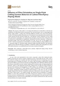
2. Ceria-stabilized Ceria-stabilized tetragonal tetragonal zirconia/alumina zirconia/alumina nanocomposite framework framework designs. designs. White Figure 2. arrows and andwhite white dotted arrows and lingual supporting structures, respectively. arrows dotted arrows showshow buccalbuccal and lingual supporting structures, respectively. Details of Details of experimental shown in Table 1. Abbreviations: B = buccal side;side; D =L distal side; experimental groups aregroups shown are in Table 1. Abbreviations: B = buccal side; D = distal = lingual side; and Mside; = mesial side. L = lingual and M = mesial side.
After sintering, sintering, the the fitness fitness of of each each framework framework was was examined examined and and corrected corrected if if necessary. necessary. Each Each After sintered framework was veneered with feldspathic ceramic via the layering technique used to sintered framework was veneered with feldspathic ceramic via the layering technique used to fabricate fabricate all-ceramic crowns. Before veneering, the surface of the framework was blasted with all-ceramic crowns. Before veneering, the surface of the framework was blasted with 50 µm Al2 O3 50 μm Alat2O0.2 3 particles at 0.2 MPa for 10 s. The distance between the framework surface and nozzle particles MPa for 10 s. The distance between the framework surface and nozzle was 10 mm. All was 10 mm. All frameworks cleaned withby ethanol, by layering distilledprocedure water. The layering frameworks were cleaned withwere ethanol, followed distilledfollowed water. The comprised procedure comprised the following: wash-bake Effect LinerH. EL, VITAGmbH Zahnfabrik Rauter the following: wash-bake (VM 9 Effect Liner EL,(VM VITA9 Zahnfabrik Rauter & Co.H. KG, Bad GmbH & Co. KG, Bad Säckingen, Germany); first and second dentin (VM 9 Base Dentin A3, VITA Säckingen, Germany); first and second dentin (VM 9 Base Dentin A3, VITA Zahnfabrik H. Rauter Zahnfabrik Rauter Co. KG); glazing,inwhich was performed in a dental furnace GmbH & Co.H.KG); andGmbH glazing,&which was and performed a dental furnace (Austromat 624, Dekema (Austromat 624, Dekema Dental-Keramiköfen GmbH, Freilassing, Germany) according to Dental-Keramiköfen GmbH, Freilassing, Germany) according to manufacturer’s instructions. Molds manufacturer’s instructions. Molds for layering porcelain on the Ce-TZP framework were made for layering porcelain on the Ce-TZP framework were made using an impression material (FUSION II using Type, an impression (FUSION II Putty Type, GC Corp., Tokyo, Japan). In brief, was a resin-up Putty GC Corp.,material Tokyo, Japan). In brief, a resin-up replica crown of each framework made replica crown of each framework was made using self-curing acrylic resin (Palavit G, Heraeus using self-curing acrylic resin (Palavit G, Heraeus Kulzer GmbH, Hanau, Germany). This replica crown Kulzer GmbH, Germany). This crown was onFor thethe Co-Cr tooth analog, an was fixed on theHanau, Co-Cr tooth analog, andreplica an impression wasfixed taken. dentin layer, base and dentin impression was taken. For the dentin layer, base dentin powder was mixed with liquid and placed powder was mixed with liquid and placed into the mold. Excess moisture was removed from the into the mold. Excess moisture was removed theand porcelain on the Ce-TZP/A framework using porcelain on the Ce-TZP/A framework using from a tissue, the framework was fired. Finally, glazing a tissue, and the framework was fired. Finally, glazing was performed. was performed. Resin tooth tooth analogs analogs were were made made from from cold cold polymerizing polymerizing resin resin (Technovit (Technovit 4000, 4000, Heraeus Heraeus Kulzer Kulzer Resin GmbH), replicating the prepared artificial tooth. The inner surfaces of the crowns and the surfaces GmbH), replicating the prepared artificial tooth. The inner surfaces of the crowns and the surfaces of the of the resin toothwere analogs were sandblasted and cleaned. ultrasonically cleaned. After pretreatment, resin tooth analogs sandblasted and ultrasonically After pretreatment, Ce-TZP/A-based Ce-TZP/A-based crowns (n = 96) to were cemented to resinusing toothself-adhesive analogs using self-adhesive resin crowns (n = 96) were cemented resin tooth analogs resin cement (RelyX cement (RelyX Unicem 2, 3M Deutschland GmbH, Neuss, Germany). This dual-cure cement was cured by chemical polymerization. During the cementation process, a constant load of 10 N was
Materials 2016, 9, 339
5 of 14
Unicem 2, 3M Deutschland GmbH, Neuss, Germany). This dual-cure cement was cured by chemical polymerization. During the cementation process, a constant load of 10 N was applied at the central fossa of each specimen, using a custom-made loading device and a stainless steel ball (diameter 4 mm). Excess cement was removed during curing. After cementation, the marginal gap of each specimen was confirmed to be in the range of clinical acceptance below 120 µm by stereomicroscopy (M400 Photomicroscope, Wild Heerbrugg AG, Heerbrugg, Switzerland) [32]. Cemented specimens were embedded in acrylic resin blocks (Palavit G, Heraeus Kulzer GmbH) in such a way that the long axis of the tooth was 2 mm below the margin line and stored in distilled water for 24 h at 37 ˝ C. Prior to fracture loading test, half of the specimens in each experimental group (n = 12) underwent chewing simulation in form of mechanical pre-loading under wet conditions using a masticator (Willytec; SD Mechatronik GmbH, Feldkirchen-Westerham, Germany). Steatite balls (diameter 5 mm) were used as antagonists. The antagonist acted on the occlusal surface of each crown. The contact points of the antagonist were adjusted using red articulating paper to confirm vertical centric loading and three-point contact. The loading simulation, which was supposed to represent five years of oral service, used the following parameters [13]: weight, 49 N; cycles, 1.2 million; frequency, 1.4 Hz; and speed, 40 mm/s. After chewing simulation, the surface of each crown was observed for prefailure by stereomicroscopy. 2.2. Fracture Load Fracture loading test of each crown either without mechanical pre-loading (´) or with mechanical pre-loading (+) was performed using a universal testing machine (Z010, Zwick GmbH, Ulm, Germany). The load was applied vertically at the central fossa of each crown using a stainless steel ball (diameter 4 mm) as a loading rod tip at a crosshead speed of 0.5 mm/min until fracture. After fracture, failure mode was observed by stereomicroscopy and scanning electron microscopy (SEM; LEO 1430, Carl Zeiss AG, Oberkochen, Germany). Failure mode was classified into two groups: partial fracture (cracking or chipping of porcelain veneer) and complete fracture (fracture of Ce-TZP/A framework or tooth analog). 2.3. Statistical Analysis All data were examined for normal distribution by Shapiro-Wilk test and for equality of the variances by Levene test. The fracture load results were analyzed by two-way analysis of variance with framework design and mechanical pre-loading as independent factors followed by Tukey’s test for post-hoc comparisons (α = 0.05). For the purpose of statistical analysis, prefailure after mechanical pre-loading was considered as complete fracture. The failure modes’ results were analyzed by Fisher’s exact test. The statistical analyses were performed by the software packages Excel Statistics 2010 (Social Survey Research Information Co., Ltd., Tokyo, Japan) and R version 3.2.3 (The R Foundation for Statistical Computing, Vienna, Austria). 3. Results 3.1. Chewing Simulation as Mechanical Pre-Loading Under stereomicroscopy observation, attrition marks due to contact with the antagonists were evident in all groups subjected to mechanical pre-loading. During chewing simulation, prefailure only occurred in the AS(+) group: three crowns (25%) exhibited cracking or chipping of the porcelain veneer and were excluded from subsequent fracture loading test. 3.2. Fracture Load The fracture load in each group is presented in Table 2; it ranged from 1866 ˘ 262 N (BS(´)) to 2049 ˘ 430 N (AS(´)) in the groups without mechanical pre-loading. No significant difference in fracture load was found between these groups. In the groups with mechanical pre-loading, the
Materials 2016, 9, 339
6 of 14
fracture load ranged from 1828 ˘ 374 N (AS(+)) to 2374 ˘ 464 N (LS(+)). The LS(+) group exhibited Materials 2016, 9, 339 6 of 13 significantly higher fracture load than the AS(+) group (p = 0.0175); however, no significant difference was evident between the AS(+) and the BS(+) and BLS(+) groups. Mechanical pre-loading tended tended to increase mean fracture loadLS(+), in theBS(+) LS(+),and BS(+) and BLS(+) while the fracture to increase mean fracture load in the BLS(+) groups,groups, while the fracture load ofload the of the anatomical design was (AS(+)) was decreased, but the differences elicited by theregime pre-loading anatomical design (AS(+)) decreased, but the differences elicited by the pre-loading were regime were notsignificant statistically significant not statistically (Figure 3). (Figure 3). Table 2.2. Fracture Fracture loads loads (N) (N) of of all-ceramic all-ceramic crowns crowns using usingdifferent differentCe-TZP/A Ce-TZP/A framework framework designs designs Table (Mean ± S.D.) (Mean ˘ Experimental Group AS Experimental Group AS Without mechanical pre-loading (−) 2049 ± 430 A,a A,a Without mechanical pre-loading ˘ 430 With mechanical pre-loading(´) (+) 2049 1828 ± 374 A,a With mechanical pre-loading (+)
1828 ˘ 374 A,a
LS LS 2040 ± 562 A,a A,a 2040 ˘ ±562 2374 464 A,b
2374 ˘ 464 A,b
BS BS 1866 ± 262 A,a A,a 1866 2009˘±262 360 A,ab
2009 ˘ 360 A,ab
BLS BLS 1897 ± 371 A,a A,a 1897 2081˘± 371 387 A,ab
2081 ˘ 387 A,ab
Results of statistical analysis are represented by upper and lower case letters. Different uppercase Results of statistical analysis are represented by upper and lower case letters. Different uppercase letters in letters in the same column indicate that the groups are significantly different (p < 0.05). Different the same column indicate that the groups are significantly different (p < 0.05). Different lowercase letters in lowercase letters in the roware indicate that different the groups are significantly differentgroups (p < 0.05). the same row indicate that same the groups significantly (p < 0.05). Details of experimental are shown in Table 1. Details of experimental groups are shown in Table 1.
Figure 3. 3. Fracture Fracture load load of of each eachexperimental experimental group. group. The The asterisk asterisk indicates indicates statistical statistical significance significance of of Figure difference between groups (p < 0.05). Details of experimental groups are shown in Table 1. difference between groups (p < 0.05). Details of experimental groups are shown in Table 1.
3.3. Failure Failure Mode Mode 3.3. The distributions distributions of of the the failure failure mode mode ratios ratios are are presented presented in in Figure Figure 4. 4. Partial Partial fractures fractures were were the the The most common failure mode, irrespective of mechanical pre-loading. Without mechanical most common failure mode, irrespective of mechanical pre-loading. Without mechanical pre-loading, pre-loading, partial ratiosfor were forBS(´), the AS(−), BS(−), and BLS(−) 83.3% for partial fracture ratiosfracture were 100% the 100% AS(´), and BLS(´) groups andgroups 83.3% and for the LS(´) the LS(−) The remaining 16.7% in group the LS(−) group werefractures. complete However, fractures. this However, this group. Thegroup. remaining 16.7% in the LS(´) were complete difference difference between the LS(−) group and the other groups was not statistically significant. between the LS(´) group and the other groups was not statistically significant. Aftermechanical mechanicalpre-loading, pre-loading, failure from to partial to complete fracture. After the the failure modemode shiftedshifted from partial complete fracture. Complete Complete fracture ratios ranged between 16.7% for andthe 41.7% for LS(+), the AS(+), LS(+), groups. and BS(+) groups. fracture ratios ranged between 16.7% and 41.7% AS(+), and BS(+) Complete Complete fracture of the AS(+) group (41.7%) was significantly enhanced compared to that of the fracture of the AS(+) group (41.7%) was significantly enhanced compared to that of the AS(´) group AS(−) group (p = 0.0372). Only the BLS(+) group developed no complete fractures after mechanical (p = 0.0372). Only the BLS(+) group developed no complete fractures after mechanical pre-loading, and pre-loading, and the partial fracture ratio remained 100%. in Complete fracture in this group was the partial fracture ratio remained at 100%. Completeat fracture this group was significantly lower significantly lower compared to other groups (p = 0.0395). compared to other groups (p = 0.0395). Details of of each each failure failure mode mode are are presented presented in in Table Table3.3. One Onepartial partial fracture fracture type—cracking type—cracking of of the the Details porcelain veneer—occurred in all frameworks except the BS(−) group. Two or three cases of cracking porcelain veneer—occurred in all frameworks except the BS(´) group. Two or three cases of cracking occurredinineach each group, the cracked arealimited was limited to the surface occlusal(Figure surface5a,b). (Figure 5a,b). occurred group, andand the cracked area was to the occlusal Chipping Chipping of the porcelain veneer, the fracture, major partial fracture,inalso occurred all groups with of the porcelain veneer, the major partial also occurred all groups withinvarying incidence. varying incidence. The chipped area was mainly on the lingual side. The crack initiations originated at load-bearing points and areas (Figure 5c,d). In more than half of the cases, crack propagation then reached the lingual cervical margin in the groups without lingual supporting structures, such as the AS and BS groups (Figure 6a), and the interface of the lingual supporting structure in the groups with lingual supporting structures, such as the LS and BLS groups (Figure 6c). In the BLS
Materials 2016, 9, 339
7 of 14
The chipped area was mainly on the lingual side. The crack initiations originated at load-bearing points and areas (Figure 5c,d). In more than half of the cases, crack propagation then reached the lingual cervical margin in the groups without lingual supporting structures, such as the AS and BS groups (Figure 6a), and the interface of the lingual supporting structure in the groups with lingual supporting structures, such as the LS and BLS groups (Figure 6c). In the BLS group, the crack ratio on the buccal structure was increased. SEM identified hackles and arrest lines. Complete Materials 2016, 9,supporting 339 7 of 13 fracture, i.e., the fracture of the Ce-TZP/A framework, occurred rarely in the LS group between the mesio cusps 5e,f). Furthermore, fractures occurred in the AS(+), group,and thedistolingual crack ratio on the (Figure buccal supporting structuretooth was analog increased. SEM identified hackles and LS, andlines. BS(+)Complete groups (Figure 5g,h). from load-bearing andrarely propagated arrest fracture, i.e.,The the fractures fracture originated of the Ce-TZP/A framework,points occurred in the to resin between tooth analog arrow). cusps (Figure 5e,f). Furthermore, tooth analog LSthe group the (Figure mesio 5h, andblack distolingual fractures occurred in the AS(+), LS, and BS(+) groups (Figure 5g,h). The fractures originated from Number of propagated respective failure of all-ceramic crowns5h, using different Ce-TZP/A Table 3. points load-bearing and to themodes resin tooth analog (Figure black arrow). framework designs.
Table 3. Number of respective failure modes of all-ceramic crowns using different Ce-TZP/A Partial Fracture Complete Fracture framework designs. Prefailure Experimental Cracking of Chipping of Cracking of Chipping of Cracking of Chipping of Group Prefailure Partial Fracture Complete Fracture Porcelain Porcelain Porcelain Porcelain Porcelain Experimental Porcelain Cracking of Chipping of Cracking of Chipping of Cracking of Chipping of Group AS(´) 3 9 0 0 Porcelain Porcelain Porcelain Porcelain Porcelain Porcelain AS(+) 2 1 2 5 0 2 AS(−) LS(´) - - 3 3 79 10 10 AS(+) 2 1 2 5 0 LS(+) 0 0 2 5 1 42 3 7 1 LS( − ) BS(´) 0 12 0 01 BS(+) 0 0 2 8 0 24 LS(+) 0 0 2 5 1 BLS(´) 2 10 0 00 0 12 0 BS(−) BLS(+) 0 0 2 10 0 0 BS(+) 0 0 2 8 0 2 Details of experimental groups 2 are shown in Table 10 1. 0 0 BLS(−) BLS(+) 0 0 2 10 0 0 Details of experimental groups are shown in Table 1.
Figure 4.4. The The distribution distribution of of failure failuremode moderatio ratioof ofeach eachexperimental experimentalgroup. group. Details Details of ofexperimental experimental Figure groups are shown in Table 1. groups are shown in Table 1.
Figure Materials 2016,4.9, The 339 distribution of failure mode ratio of each experimental group. Details of experimental8 of 14 groups are shown in Table 1.
Materials 2016, 9, 339
8 of 13
Figure 5. Cont.
Figure 5. Microscopy (overview; left) and scanning electron microscopy (detail; right) observation of Figure 5. Microscopy (overview; left) and scanning electron microscopy (detail; right) observation of various failure modes. Cracking (a,b); chipping of porcelain (c,d); fracture of framework (e,f); and various failure modes. Cracking (a,b); chipping of porcelain (c,d); fracture of framework (e,f); and tooth analog (g,h). Black arrows, asterisks, and black dotted circles indicate fracture lines, tooth analog (g,h). Black arrows, asterisks, and black dotted circles indicate fracture lines, load-bearing load-bearing points, and areas, respectively. points, and areas, respectively.
Figure 5. Microscopy (overview; left) and scanning electron microscopy (detail; right) observation of various failure modes. Cracking (a,b); chipping of porcelain (c,d); fracture of framework (e,f); and Materials 2016, 9, 339 (g,h). Black arrows, asterisks, and black dotted circles indicate fracture lines,9 of 14 tooth analog load-bearing points, and areas, respectively.
Materials 2016, 9, 339
9 of 13
Figure 6. Cont.
Figure 6. Lingual side views of microscopy (overview; left) and scanning electron microscopy Figure 6. Lingual side views of microscopy (overview; left) and scanning electron microscopy (detail; (detail; right) observation; non-lingual supporting structure (a,b); lingual supporting structure (c,d). right) observation; non-lingual supporting structure (a,b); lingual supporting structure (c,d). White White arrows, white dotted arrows, and asterisks indicate fracture lines, arrest lines, and arrows, white dotted arrows, and asterisks indicate fracture lines, arrest lines, and load-bearing load-bearing points, respectively. points, respectively.
4. Discussion 4. Discussion Chipping of veneered all-ceramic restorations is still a problem. One approach to overcome Chipping veneered all-ceramic restorations still of a problem. One approach to overcome this this problem is of modification of the framework. Theis aim this study was the investigation of the problem is modification of the framework. The aim of this study was the investigation of the influence influence of different framework designs including several supporting structures on the fracture of different framework designs including several supporting structures on the fracture and failure load and failure mode of veneered Ce-TZP/A crowns. A standard anatomical shape load was compared mode of veneered Ce-TZP/A crowns. A standard anatomical shape was compared to modified designs to modified designs with supporting buccal/lingual structures. All groups were tested for fracture with supporting buccal/lingual structures. All groups were tested for fracture load and failure mode load and failure mode with or without a mechanical pre-loading regime simulating five years of with oruse. without a mechanical pre-loading regime simulating five years use. The Mechanical clinical Mechanical pre-loading did not influence the fracture load of inclinical all groups. failure pre-loading did not themechanical fracture load in all groups. The failureexcept mode,the however, was affected mode, however, wasinfluence affected by pre-loading in all groups BLS design. In the by mechanical pre-loading in all groups except the BLS design. In the LS and BS groups, an increased LS and BS groups, an increased amount of complete fractures was observed. In the AS group, even amount ofwas complete fractures was observed. In the AS group, even prefailure was hand, observed prefailure observed after mechanical pre-loading. The BLS group, on the other wasafter the mechanical pre-loading. The BLS group, on the other hand, was the only design showing solely only design showing solely partial fractures under both tested conditions. Thus, our firstpartial null fractures under both tested conditions. Thus, first null hypothesis was accepted, and our second hypothesis was accepted, and our second was our rejected. was Chipping rejected. commonly occurs at the cusp or marginal ridge area of molar all-ceramic crowns Chipping commonly occurs at the cusp or marginal ridgesupport area of molar crowns [25,33]. [25,33]. Veneering porcelain is a brittle material and requires by theall-ceramic underlying framework. Veneering porcelain is astructure brittle material and requires support by thenot underlying lingual A lingual supporting improved the fracture strength only in framework. zirconia butAalso in supporting structure improved the fracture strength not only in zirconia but also in glass-infiltrated glass-infiltrated alumina and metal-ceramic [34]. In the mandibular molar region, the buccal cusps alumina and metal-ceramic [34]. In the mandibular molarocclusal region,forces the buccal cusps act asand functional act as functional cusps and are subjected to concentrated during chewing biting cusps and are subjected to concentrated occlusal forces during chewing and biting [35]. An additional [35]. An additional buccal cusp support is necessary to withstand those occlusal forces [12]. In this buccalthe cusp support to design withstand occlusalbuccal forcesand [12].lingual In this supporting study, the concept of a study, concept ofisa necessary framework withthose additional structures framework design with additional buccalHowever, and lingual based was based on previous studies [17,36]. a supporting supporting structures structure was similar to on theprevious lingual studies [17,36]. However, a supporting structure similar to the lingual supporting structure supporting structure as described by Silva et al. [16] was not applicable to the buccal side as as it would be directly visible and would not satisfy patients’ esthetic demands. An alternative framework design for metal-ceramic restorations features a two-sided supporting structure designed by adding buccal and lingual cusps to the framework’s surface; it exhibits improved fracture strength [36]. In this framework, the buccal supporting structure is invisible after veneering. The buccal and lingual supporting structures described in our study were selected for the simplicity
Materials 2016, 9, 339
10 of 14
described by Silva et al. [16] was not applicable to the buccal side as it would be directly visible and would not satisfy patients’ esthetic demands. An alternative framework design for metal-ceramic restorations features a two-sided supporting structure designed by adding buccal and lingual cusps to the framework’s surface; it exhibits improved fracture strength [36]. In this framework, the buccal supporting structure is invisible after veneering. The buccal and lingual supporting structures described in our study were selected for the simplicity of their manufacture. They incorporated features of both framework designs, comprising internal buccal and external lingual supporting structures after veneering with porcelain. In this study, prefailure during mechanical pre-loading was regarded as a complete fracture for statistical analysis. The rationale behind this decision was that for the observed prefailure modes, the actual crown normally has to be removed and replaced by a new one in a clinical situation. Without mechanical pre-loading, there was no significant difference in the fracture load and failure mode among the framework designs. Fracture load causes tensile stress in the porcelain veneer of bilayered all-ceramic crowns. The most frequent failure modes were partial fracture (i.e., chipping of the porcelain veneer). Fracture originated at load-bearing points in all specimens. The chipped area was mainly on the lingual side, and crack propagation of the cohesive/adhesive fracture reached the cervical margin or interface of the lingual supporting structure (Figure 6a,c). Therefore, crack propagation from the central fossa towards the cervical margin and proximal area was identified by indicators such as hackles and arrest lines under SEM observation (Figure 6b,d). These findings may be explained by the location of load-bearing points. Kirsten et al. [37] used nine defined loading areas to simulate a physiological mastication behavior. The distribution of the maximum tensile stress was concentrated in the occlusal fissures between the mesiolingual and distobuccal cusps in Y-TZP crowns. In our study, the vertical load was applied at three contact points centered around the central fossa. Therefore, the load-bearing points were concentrated in the lingual side because two of the three contact points were located in the occlusal fissure between the mesio and distolingual cusps (Figure 5c). Without mechanical pre-loading, partial fractures were observed in all groups, and only the LS(´) group showed already 16.7% of complete fracture. The different outcome compared to the BS(´) group may be explained by the location of the supporting structure. It has been reported that an extra-thick occlusal support reduced chipping and improved the fracture pattern [38]. Haker [36] suggested that additional two-sided supporting structures, which were similar to our buccal supporting structure, could enhance the porcelain’s strength by lowering the compressive stress between the porcelain and the metal framework due to stress dispersion. In our framework designs, the lingual supporting structure cannot increase the occlusal support area, while the buccal supporting structure can increase the area of the occlusal surface. Thus, only the buccal supporting structure could attain a stress dispersion. On the other hand, crack propagation could be stopped at the interface of the lingual supporting structure by its superior mechanical characteristic because the lingual supporting structure was only partially veneered with porcelain, whereas the buccal supporting structure was completely covered. Generally, the influence of artificial aging on fracture load in Y-TZP crowns is investigated by a combination of thermocycling and cyclic loading [13,19]. The thermocycling treatment is included to simulate the influence of LTD on Y-TZP restorations under clinical conditions. In several studies, it has been reported that Ce-TZP/A exhibited complete resistance to LTD [39,40]. Therefore, in this study dealing with Ce-TZP/A crowns, only mechanical pre-loading was performed to simulate clinical use. After mechanical pre-loading, the fracture load tended to decrease in frameworks without additional supporting structures (AS), whereas fracture load tended to increase in frameworks with additional supporting structures (LS, BS, and BLS). These differences may be explained by two factors: zirconia transformation toughening and porcelain degradation. It has been confirmed in several studies that zirconia phase transformation caused by external stress is one factor influencing fracture load. External stress, such as LTD, changed the
Materials 2016, 9, 339
11 of 14
phase transformation and produced positive as well as negative effects on Y-TZP mechanical properties [41]. The flexural strength increased by increasing the monoclinic contents up to 12% (transformation toughening); however, the flexural strength decreased with higher monoclinic contents. Von Steyern et al. [19] showed that Y-TZP crowns exhibited higher fracture loads after cyclic loading. They stated that the fracture load can be increased by cyclic loading up to a certain transformation toughening capacity. Our results indicate that the additional supporting structures seemed to have increased this transformation toughening capacity by increasing the framework sizes, thus contributing to the higher fracture loads in the LS, BS, and BLS groups. In contrast, the AS(+) group obviously had already reached the limit of its toughening capacity by the mechanical pre-loading stress. This assumption is confirmed by the high level of prefailures in the AS(+) group. In our study, the incidence of complete fracture for all framework designs except for the BLS group was increased after mechanical pre-loading. It has been shown that even the combination of mechanical pre-loading and thermocycling does not affect the phase transformation or fracture properties of Ce-TZP/A [42]. However, the fatigue induced by cyclic loading can influence the strength of the porcelain veneer [43]. Obviously, mechanical pre-loading influenced the failure mode in our framework designs because continual compressive stress accelerated the degradation of the porcelain veneer and crack propagation. Particularly, prefailures of the AS group may have been caused by the more pronounced porcelain degradation in the thick porcelain layer of this group: In this framework design without supporting structures, a higher porcelain amount was required so that the ratio between the veneering ceramic and zirconia framework was suboptimal. It has been demonstrated that the amount or thickness of the veneering porcelain affects stress distribution within the porcelain layer in Y-TZP crowns [34,44]. The incidence of cracking rises with increasing the porcelain veneer thickness, at least for Y-TZP crowns [45]. In our study, the ratio of porcelain to Ce-TZP/A framework (1.2–1.7 mm/0.3 mm = 4–5.7) is higher than in other studies using Y-TZP (1.0 mm/0.5–0.6 mm = 1.67–2) as base material [14,34]. The results of our tests indicate that a 0.3 mm framework without additional supporting structures offers insufficient support to an artificially aged, comparatively thick porcelain layer under simulation of clinical conditions. Among the supporting structure designs, the BLS design can reduce the amount of porcelain veneer compared to the BS and LS group so that this framework design showed significantly lower complete fractures after mechanical pre-loading. Although the framework design of the BLS group consists of a more complicated structure than the other tested designs, this framework combines the advantages of both buccal and lingual supporting structures. 5. Conclusions The modification of anatomically designed Ce-TZP/A crowns by the addition of buccal and/or lingual supporting structures (BS, LS and BLS) tended to increase the fracture load after mechanical pre-loading simulating five years of clinical use for all three tested designs. The increase in the fracture load, however, was statistically significant only for the lingual support group LS(+). Incidence and severity of the failure mode, however, were positively affected by all framework designs with additional supporting structures. Without mechanical pre-loading, the most common failure modes were partial fractures among all framework designs. After mechanical pre-loading, 41.7% complete failures were observed in the anatomical design (AS) reference group, partly the samples that already failed during simulated clinical use (pre-failure). All modified designs with buccal and/or lingual supporting structures led to a more or less pronounced reduction of prefailures and complete failures, shifting the failure mode from complete to partial fracture. Especially one Ce-TZP/A framework design (BLS), comprised of a basic anatomical shape modified with additional buccal and lingual structures, prevented total fractures completely, showing only partial fractures even after mechanical pre-loading. Within the limits of this in vitro study, this Ce-TZP/A framework design has shown potential to reduce chipping of the veneering porcelain in clinical practice.
Materials 2016, 9, 339
12 of 14
Acknowledgments: The authors are grateful to Panasonic Healthcare, especially Fumio Sugata and Tomohiro Udaka, for providing the samples and technical advice. The authors are also grateful to Dekema Dental-Keramiköfen for supporting the dental furnace. We further acknowledge support by Deutsche Forschungsgemeinschaft and Open Access Publishing Fund of University of Tübingen. Author Contributions: Tomofumi Sawada and Sebastian Spintzyk conceived and designed the experiments; Tomofumi Sawada, Sebastian Spintzyk, Christine Schille, and Ernst Schweizer performed the experiments; Lutz Scheideler and Jürgen Geis-Gerstorfer conceived and designed the experiments, commented and critically revised the manuscript; Tomofumi Sawada analyzed the data and wrote the paper. All authors read the final paper and approved. Conflicts of Interest: The authors declare no conflict of interest.
References 1. 2.
3. 4. 5. 6. 7.
8. 9.
10. 11. 12.
13. 14. 15.
16. 17. 18.
Miyazaki, T.; Nakamura, T.; Matsumura, H.; Ban, S.; Kobayashi, T. Current status of zirconia restoration. J. Prosthodont. Res. 2013, 57, 236–261. [CrossRef] [PubMed] Pjetursson, B.E.; Sailer, I.; Zwahlen, M.; Hämmerle, C.H. A systematic review of the survival and complication rates of all-ceramic and metal-ceramic reconstructions after an observation period of at least 3 years. Part I: Single crowns. Clin. Oral Implants Res. 2007, 18 (Suppl. S3), 73–85. [CrossRef] [PubMed] Pelaez, J.; Cogolludo, P.G.; Serrano, B.; Serrano, J.F.; Suarez, M.J. A four-year prospective clinical evaluation of zirconia and metal-ceramic posterior fixed dental prostheses. Int. J. Prosthodont. 2012, 25, 451–458. [PubMed] Larsson, C.; Wennerberg, A. The clinical success of zirconia-based crowns: A systematic review. Int. J. Prosthodont. 2014, 27, 33–43. [CrossRef] [PubMed] Agustín-Panadero, R.; Román-Rodríguez, J.L.; Ferreiroa, A.; Solá-Ruíz, M.F.; Fons-Font, A. Zirconia in fixed prosthesis. A literature review. J. Clin. Exp. Dent. 2014, 6, e66–e73. [CrossRef] [PubMed] Heintze, S.D.; Rousson, V. Survival of zirconia- and metal-supported fixed dental prostheses: A systematic review. Int. J. Prosthodont. 2010, 23, 493–502. [PubMed] Ferrari, M.; Giovannetti, A.; Carrabba, M.; Bonadeo, G.; Rengo, C.; Monticelli, F.; Vichi, A. Fracture resistance of three porcelain-layered CAD/CAM zirconia frame designs. Dent. Mater. 2014, 30, e163–e168. [CrossRef] [PubMed] Omori, S.; Komada, W.; Yoshida, K.; Miura, H. Effect of thickness of zirconia-ceramic crown frameworks on strength and fracture pattern. Dent. Mater. J. 2013, 32, 189–194. [CrossRef] [PubMed] Schmitter, M.; Mueller, D.; Rues, S. In vitro chipping behaviour of all-ceramic crowns with a zirconia framework and feldspathic veneering: Comparison of CAD/CAM-produced veneer with manually layered veneer. J. Oral Rehabil. 2013, 40, 519–525. [CrossRef] [PubMed] Paula, V.G.; Lorenzoni, F.C.; Bonfante, E.A.; Silva, N.R.; Thompson, V.P.; Bonfante, G. Slow cooling protocol improves fatigue life of zirconia crowns. Dent. Mater. 2015, 31, 77–87. [CrossRef] [PubMed] Jakubowicz-Kohen, B.D.; Sadoun, M.J.; Douillard, T.; Mainjot, A.K. Influence of firing time and framework thickness on veneered Y-TZP discs curvature. Dent. Mater. 2014, 30, 242–248. [CrossRef] [PubMed] Tinschert, J.; Schulze, K.A.; Natt, G.; Latzke, P.; Heussen, N.; Spiekermann, H. Clinical behavior of zirconia-based fixed partial dentures made of DC-Zirkon: 3-year results. Int. J. Prosthodont. 2008, 21, 217–222. [PubMed] Rosentritt, M.; Steiger, D.; Behr, M.; Handel, G.; Kolbeck, C. Influence of substructure design and spacer settings on the in vitro performance of molar zirconia crowns. J. Dent. 2009, 37, 978–983. [CrossRef] [PubMed] Kokubo, Y.; Tsumita, M.; Kano, T.; Fukushima, S. The influence of zirconia coping designs on the fracture load of all-ceramic molar crowns. Dent. Mater. J. 2011, 30, 281–285. [CrossRef] [PubMed] Guess, P.C.; Bonfante, E.A.; Silva, N.R.; Coelho, P.G.; Thompson, V.P. Effect of core design and veneering technique on damage and reliability of Y-TZP-supported crowns. Dent. Mater. 2013, 29, 307–316. [CrossRef] [PubMed] Silva, N.R.; Bonfante, E.A.; Rafferty, B.T.; Zavanelli, R.A.; Rekow, E.D.; Thompson, V.T.; Coelho, P.G. Modified Y-TZP core design improves all-ceramic crown reliability. J. Dent. Res. 2011, 90, 104–108. [CrossRef] [PubMed] Marchack, B.W.; Futatsuki, Y.; Marchack, C.B.; White, S.N. Customization of milled zirconia copings for all-ceramic crowns: A clinical report. J. Prosthet. Dent. 2008, 99, 169–173. [CrossRef] Guazzato, M.; Proos, K.; Quach, L.; Swain, M.V. Strength, reliability and mode of fracture of bilayered porcelain/zirconia (Y-TZP) dental ceramics. Biomaterials 2004, 25, 5045–5052. [CrossRef] [PubMed]
Materials 2016, 9, 339
19.
20. 21. 22. 23.
24.
25. 26.
27. 28.
29.
30.
31.
32. 33. 34. 35. 36. 37. 38.
39.
40.
13 of 14
Von Steyern, P.V.; Ebbesson, S.; Holmgren, J.; Haag, P.; Nilner, K. Fracture strength of two oxide ceramic crown systems after cyclic pre-loading and thermocycling. J. Oral Rehabil. 2006, 33, 682–689. [CrossRef] [PubMed] Chevalier, J. What future for zirconia as a biomaterial? Biomaterials 2006, 27, 535–543. [CrossRef] [PubMed] Lughi, V.; Sergo, V. Low temperature degradation-aging-of zirconia: A critical review of the relevant aspects in dentistry. Dent. Mater. 2010, 26, 807–820. [CrossRef] [PubMed] Cattani-Lorente, M.; Scherrer, S.S.; Ammann, P.; Jobin, M.; Wiskott, H.W. Low temperature degradation of a Y-TZP dental ceramic. Acta Biomater. 2011, 7, 858–865. [CrossRef] [PubMed] Monaco, C.; Caldari, M.; Scotti, R. Clinical evaluation of 1132 zirconia-based single crowns: A retrospective cohort study from the AIOP clinical research group. Int. J. Prosthodont. 2013, 26, 435–442. [CrossRef] [PubMed] Monaco, C.; Caldari, M.; Scotti, R. Clinical evaluation of tooth-supported zirconia-based fixed dental prostheses: A retrospective cohort study from the AIOP clinical research group. Int. J. Prosthodont. 2015, 28, 236–238. [PubMed] Beuer, F.; Stimmelmayr, M.; Gernet, W.; Edelhoff, D.; Güh, J.F.; Naumann, M. Prospective study of zirconia-based restorations: 3-year clinical results. Quintessence Int. 2010, 41, 631–637. [PubMed] Lorenzoni, F.C.; Martins, L.M.; Silva, N.R.; Coelho, P.G.; Guess, P.C.; Bonfante, E.A.; Thompson, V.P.; Bonfante, G. Fatigue life and failure modes of crowns systems with a modified framework design. J. Dent. 2010, 38, 626–634. [CrossRef] [PubMed] Nawa, M.; Nakamoto, S.; Sekino, T.; Niihara, K. Tough and strong Ce-TZP/Alumina nanocomposites doped with titania. Ceram. Int. 1998, 24, 497–506. [CrossRef] Philipp, A.; Fischer, J.; Hämmerle, C.H.; Sailer, I. Novel ceria-stabilized tetragonal zirconia/alumina nanocomposite as framework material for posterior fixed dental prostheses: Preliminary results of a prospective case series at 1 year of function. Quintessence Int. 2010, 41, 313–319. [PubMed] Ban, S.; Sato, H.; Suehiro, Y.; Nakanishi, H.; Nawa, M. Biaxial flexure strength and low temperature degradation of Ce-TZP/Al2 O3 nanocomposite and Y-TZP as dental restoratives. J. Biomed. Mater. Res. B Appl. Biomater. 2008, 87, 492–498. [CrossRef] [PubMed] Tanaka, K.; Tamura, J.; Kawanabe, K.; Nawa, M.; Uchida, M.; Kokubo, T.; Nakamura, T. Phase stability after aging and its influence on pin-on-disk wear properties of Ce-TZP/Al2 O3 nanocomposite and conventional Y-TZP. J. Biomed. Mater. Res. A 2003, 67, 200–207. [CrossRef] [PubMed] Tanaka, S.; Takaba, M.; Ishiura, Y.; Kamimura, E.; Baba, K. A 3-year follow-up of ceria-stabilized zirconia/alumina nanocomposite (Ce-TZP/A) frameworks for fixed dental prostheses. J. Prosthodont. Res. 2015, 59, 55–61. [CrossRef] [PubMed] Martínez-Rus, F.; Suárez, M.J.; Rivera, B.; Pradíes, G. Evaluation of the absolute marginal discrepancy of zirconia-based ceramic copings. J. Prosthet. Dent. 2011, 105, 108–114. [CrossRef] Anusavice, K.J. Standardizing failure, success, and survival decisions in clinical studies of ceramic and metal-ceramic fixed dental prostheses. Dent. Mater. 2012, 28, 102–111. [CrossRef] [PubMed] Bonfante, E.A.; da Silva, N.R.F.A.; Coelho, P.G.; Bayardo-Gonzalez, D.E.; Thompson, V.P.; Bonfante, G. Effect of framework design on crown failure. Eur. J. Oral Sci. 2009, 117, 194–199. [CrossRef] [PubMed] Wang, M.; Mehta, N. A possible biomechanical role of occlusal cusp-fossa contact relationships. J. Oral Rehabil. 2013, 40, 69–79. [CrossRef] [PubMed] Haker, G. Structural design for a metal framework (I). Quintessenz Zahntech. 1984, 10, 83–91. [PubMed] Kirsten, A.; Parkot, D.; Raith, S.; Fischer, H. A cusp supporting framework design can decrease critical stresses in veneered molar crowns. Dent. Mater. 2014, 30, 321–326. [CrossRef] [PubMed] Alhasanyah, A.; Vaidyanathan, T.K.; Flinton, R.J. Effect of core thickness differences on post-fatigue indentation fracture resistance of veneered zirconia crowns. J. Prosthodont. 2013, 22, 383–390. [CrossRef] [PubMed] Inokoshi, M.; Vanmeensel, K.; Zhang, F.; De Munck, J.; Eliades, G.; Minakuchi, S.; Naert, I.; Van Meerbeek, B.; Vleugels, J. Aging resistance of surface-treated dental zirconia. Dent. Mater. 2015, 31, 182–194. [CrossRef] [PubMed] Chevalier, J.; Gremillard, L.; Virkar, A.V.; Clarke, D.R. The tetragonal-monoclinic transformation in zirconia: Lessons learned and future trends. J. Am. Ceram. Soc. 2009, 92, 1901–1920. [CrossRef]
Materials 2016, 9, 339
41. 42.
43. 44.
45.
14 of 14
Kim, H.T.; Han, J.S.; Yang, J.H.; Lee, J.B.; Kim, S.H. The effect of low temperature aging on the mechanical property & phase stability of Y-TZP ceramics. J. Adv. Prosthodont. 2009, 1, 113–117. [PubMed] Güngör, M.B.; Yılmaz, H.; Aydın, C.; Nemli, S.K.; Bal, B.T.; Tıra¸s, T. Biaxial flexural strength and phase transformation of Ce-TZP/Al2 O3 and Y-TZP core materials after thermocycling and mechanical loading. J. Adv. Prosthodont. 2014, 6, 224–232. [CrossRef] [PubMed] White, S.N.; Li, Z.C.; Yu, Z.; Kipnis, V. Relationship between static chemical and cyclic mechanical fatigue in a feldspathic porcelain. Dent. Mater. 1997, 13, 103–110. [CrossRef] Ha, S.R.; Kim, S.H.; Han, J.S.; Yoo, S.H.; Jeong, S.C.; Lee, J.B.; Yeo, I.S. The influence of various core designs on stress distribution in the veneered zirconia crown: A finite element analysis study. J. Adv. Prosthodont. 2013, 5, 187–197. [CrossRef] [PubMed] Benetti, P.; Pelogia, F.; Valandro, L.F.; Bottino, M.A.; Bona, A.D. The effect of porcelain thickness and surface liner application on the fracture behavior of a ceramic system. Dent. Mater. 2011, 27, 948–953. [CrossRef] [PubMed] © 2016 by the authors; licensee MDPI, Basel, Switzerland. This article is an open access article distributed under the terms and conditions of the Creative Commons Attribution (CC-BY) license (http://creativecommons.org/licenses/by/4.0/).