Bellcore, Red Bank, New Jersey 07701-7040. (Received 27 August ... in the keV range with an emphasis on the temperature dependence of the damage ..... S. Harris, F. H. Eisen, B. Welch, J. D. Haskell, R. D. Pashley, and. J. W. Mayer, Appl.
Influence of substrate temperature on lattice strain field and phase transition in MeV oxygen ion implanted GaAs crystals Fulin Xiong,a) C. J. Tsai, T. Vreeland, Jr., and T. A. Tombrello California Institute of Technology, Pasadena, California 91125
C. L. Schwartz and S. A. Schwarz Bellcore, Red Bank, New Jersey 07701-7040
(Received 27 August 1990; accepted for publication 3 December 1990) A detailed study of the influence of substrate temperature on the radiation-induced lattice strain field and crystalline-to-amorphous (c-a) phase transition in MeV oxygen ion implanted GaAs crystals has been made using channeling Rutherford backscattering spectroscopy, secondary ion mass spectrometry, and the x-ray rocking curve technique. A comparison has been made between the cases of room temperature (RT) and low temperature (LT) (about 100 K) implantation. A strong in situ dynamic annealing process is found in RT implantation at a moderate beam current, resulting in a uniform positive strain field in the implanted layer. LT implantation introduces a freeze-in effect which impedes the recombination and diffusion of initial radiation-created lattice damage and defects, and in turn drives more efficiently the c-u transition as well as strain saturation and relaxation. The results are interpreted with a spike damage model in which the defect production process is described in terms of the competition between defect generation by nuclear spikes and defect diffusion and recombination stimulated by electronic spikes. It is also suggested that the excess population of vacancies and their complexes is responsible for lattice spacing expansion in ion-implanted GaAs crystals.
I. INTRODUCTION Ion implantation as a well-established technique for introducing active doping and for property modification in semiconductors has been widely utilized in semiconductor device technology. Tremendous effort has been devoted to understand the physical processes and effects involved and to ensure its highly precise control capability and reproducibility. ‘-’ However, many aspects, from the fundamental study of mechanisms of radiation-induced damage and activation processes to the reproducible control of conditions of implantation and annealing, are still not well understood-especially in the area of MeV ion implantation. The connection between the implantation condition and structure and distribution of radiation-induced defects is of high scientific and technological interest because of the fact that electrical and structural properties of implanted samples as well as post-implantation processes necessary for damage annealing and dopant activation, are highly influenced by the degree of lattice disorder and damage. This may be much more pronounced in III-V compound semiconductors, as compared to Si, due to their binary nature and complexity of lattice defects. Investigation of ion implantation into GaAs has attracted considerable attention as it is widely used in fabricating optoelectronic and high speed devices. Among many influences on defect production and annihilation during ion implantation, the substrate temperature is one of the most important factors. Many studies of the GaAs system have been made in the keV range with an
emphasis on the temperature dependence of the damage profile, critical amorphization dose,3-5 and electrical property6 of implanted samples. A significant in situ annealing process has been noticed to be involved during the implantation at room temperature and above.3’7 Similar phenomena have been found in MeV ion implantation.’ The present study of implantation and characterization in MeV oxygen ion implanted GaAs was carried out using the x-ray rocking curve (XRC) technique, channeling Rutherford backscattering spectrometry (CRBS), and secondary ion mass spectrometry (SIMS), to investigate the influence of substrate temperature on the implant profile, lattice damage, radiation-induced strain field, and phase transition during implantation. The results have consistently revealed that strong defect diffusion and in situ dynamic annealing are involved during implantation at room temperature with a moderate beam current, resulting in lattice strain build-up and saturation. The expected amorphization was not observed under this condition. Implantation at low temperature (about 100 K) introduces a freezing-in effect. It impedes initial radiation-created lattice damage and defects from recombination and diffusion, and in turn drives more efficiently the c-a transition as well as lattice strain saturation and relaxation during implantation. The results have given us a close insight of ion damage nucleation in III-V compound semiconductors with the influence of substrate temperature.
“Present address: Gordon McKay Laboratory of Applied Science, Harvard University, Cambridge, MA 02138. 2964
J. Appl. Phys. 69 (5), 1 March 1991
0021-8979/91/052964-06$03.00
@ 1991 American Institute of Physics
2964
Downloaded 16 Dec 2005 to 131.215.225.9. Redistribution subject to AIP license or copyright, see http://jap.aip.org/jap/copyright.jsp
*
II. EXPERIMENTAL
ASPECTS AND RESULTS
An n-type GaAs( 100) single crystalline wafer, doped with Si at a carrier concentration of 4.7 x 10’*/cm3, was used in this study. 2 MeV oxygen ions generated from the Caltech Tandem accelerator were implanted into GaAs substrates with doses ranging from 5 x 10¹³ to 2 X 10¹⁶ ions/cm2. The implantation was carried out with the target maintained either at ambient room temperature (RT) or at low temperature (LT) with LN2 cooling (about 100 K on the target surface). The focused and electrostatically rastered beam was projected to the sample surface in a nonchanneling direction through a 6 x 6 mm2 collimator. The beam current density in all cases was maintained constant at 2.5 X lOI ions/cm2 s. Characterization of both RT and LT implanted samples was done at room temperature. The implant distribution was profiled by SIMS at Bellcore laboratory with a 16 keV Art source. Crystalline damage profiling was investigated with CRBS on the Caltech Tandem accelerator. In order to probe deeply buried implanted layers, a 4 MeV 4He’ beam was used. A solid-state detector was set at a lab angle of 140”, which is chosen to give a flat cross section function and minimize the possible resonant scattering from ‘60(a,a) ‘60.8v9 T he net dechanneling ratio at a certain depth was extracted as x = (Ci - Ce)/(C, - Ce), where Ce, Ci, and C, are CRBS yields from a virgin crystal and an implantation-damaged crystal, and the yield in the random spectrum, respectively. Measurement of lattice strain profiles was performed with the XRC technique which is based on Bragg double-crystal x-ray diffraction. The sample to be analyzed is mounted as the second crystal on a goniometer which rotated in steps of 10 - 4 deg around the preset Bragg angle of the required diffraction direction of the substrate. An x-ray rocking curve is just a measure of the change of x-ray diffraction intensity (reflecting power) as a function of the small variation of Bragg angle (he) due to lattice strain and crystal imperfections. The well collimated, low divergence FeKo, x-ray (A = 1.936 A), monochromized by the first crystal of GaAs(400), was used. Symmetrical (400) diffraction with respect to the substrate was aligned for perpendicular strain measurement, and asymmetrical diffraction in the (3 11) direction for parallel strain detection. By deconvolution of XRCs with well-known analytical models,10-‘2 one can obtain information on depth profiles of lattice strain and crystalline damage. In our case, the dynamical x-ray diffraction model,1”‘2 which properly accounts for absorption and extinction of x-ray wave fields in the implanted layer, has been employed due to the deep implantation. In this model, the degree of lattice disorder is taken into account by introducing a term called “damage,” which represents the standard deviation of a Gaussian distribution of atomic radial displacement of lattice atoms from their lattice sites. It reduces the x-ray reflecting intensity due to a change of the crystalline structural factor of the sample through the well-known Debye-Waller correction factor.10,13 We note here that the solution for the deconvolution of experimental XRCs is not unique; it requires preliminary knowledge of physical qualities involved. In our detailed data analysis, 2965
J. Appl. Phys., Vol. 69, No. 5, 1 March 1991
3.0X10’~,,,,,,,,,,~,~~,‘.“,.“’
0.4
- 2 MeV Oxygen Ions into Gab 2.5 - Distribution of lmplanls
Depth
(v)
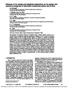
FIG. 1. Distributions of 2 MeV implanted oxygen atoms and implantation-created vacancies in GaAs, calculated by the TRIM code.
the initial estimate of the profiles of lattice strain and damage was chosen according to the implant distribution established by SIMS and the distribution of implantationinduced vacancies estimated by a TRIM simulation, respectively, with an assumption that the strain is proportional to the concentration of lattice defects and the damage is proportional to the implant distribution. Then, these profiles were modified so as to best fit the calculated x-ray rocking curves to the experimental ones. Figure 1 shows a computer simulation result of the distribution of implanted atoms and implantation-created vacancies for 2 MeV oxygen ions in GaAs, which was calculated with the TRIM code14T15with a displacement energy of 10 eV. As a preliminary estimate, it predicts that the implanted atoms follow a distorted Gaussian distribution with an average range of 1.72 pm and the standard deviation of 0.23 pm (FWHM = 0.23 ~2.36 ,um = 0.54 pm). The profile of implantation-generated vacancies has a slight shift towards the surface with respect to the implant distribution with a damage tail extending in the surface region. Since the TRIM calculation15 is based on Monte Carlo simulation of energetic ion transportation in a randomly oriented material, no information about crystalline structure, damage overlap, and defect migration and annihilation has been taken into account. The SIMS profiles of oxygen in both RT and LT implanted GaAs samples are shown in Fig. 2. The data have been normalized by setting the integrated yield equal to unity. The profiles indicate a distorted Gaussian-like distribution with the peak at 1.85 pm and the FWHM of 0.55 pm. No significant difference between the profiles of these two samples has been found, except a slight broadening in the RT implanted sample. This implies that only weak implant diffusion might have taken place during the RT implantation. In contrast, a strong influence of target temperature on lattice disorder and damage profiles has been revealed by the CRBS measurement. Two sets of CRBS spectra from RT and LT implanted samples Fig. 3 show the evolution of lattice damage as a function of the ion dose. In the LT implanted samples [Fig. 3 (a)], lattice disorder increases markedly with the ion dose. A highly disordered region is Xiong et al.
2985
Downloaded 16 Dec 2005 to 131.215.225.9. Redistribution subject to AIP license or copyright, see http://jap.aip.org/jap/copyright.jsp
g&f 1
x: RT Implantation c: LT Implantation
0
0
2
i
q
d
LT Implantation FIT lmplantarion
Dose (ions/cm*)
Depth (w4
FIG. 2. SIMS oxygen profiles in GaAs implanted by 2 MeV oxygen ions atRT(X)andatLT(+).
centered at a depth around 1.75 ,um, consistent with the profiles from TRIM simulation. Figure 4 plots the net dechanneling ratio at this point ( - 1.7 pm) as a function of the dose. At low doses ( 10’3-1014 ions/cm2), lattice damage accumulates with the dose D as x = CD”, since a straight line in a log-log plot is shown, with n N 1.198 and
5x F
0’ 1.5 23 P j:
1.0
0.5
,,,a “.”
0
2
1 Depth
2.5~104
3
(w)
I”“I”“J
--I - 1: Random
2: 2x10’6
@I
3: 1x10’6
-
- 7: virgin
3 F
1.0
0.5
0.0
0
1
2
3
Depth (!-W FIG. 3. CRBS spectra for 2-MeV-oxygen-ion-implanted GaAs, showing the evolution of lattice damage as a function of the implant dose. (a) LT implanted, (b) RT implanted. 2966
J. Appl. Phys., Vol. 69, No. 5, 1 March 1991
FIG. 4. The net dechanneling ratio in the heavily damaged region as a function of the implant dose in 2-MeV-oxygen-ion-implanted GaAs. The data are taken from Fig. 3.
c = 6.09 x 10 - 16. The completed amorphization takes place with a threshold dose around 1 X lOI ions/cm2. In the subsurface region [see Fig. 3(a)], lattice damage accumulates very slowly with increasing dose. However, there is a big jump of the damage level at a dose of 1 X lOI ions/cm2, where the dechanneling yield in the deep implanted layer reaches the level for the random case. The thickness of the amorphous layer increases as the dose increases. At very high doses (over 1 X 10¹⁶ ions/cm*) the entire surface layer is amorphized, resulting in an amorphous layer about 2 pm thick. In the RT implanted samples [Fig. 3(b)], it is found that lattice disorder is much less pronounced. As normally expected, the surface region has suffered minimal radiation-induced structural damage. The heavily damaged region lies a little deeper than in the LT implanted sample. The behavior of lattice damage at this point (- 1.9 pm) as a function of the dose, as plotted in Fig. 4, differs markedly from the case of RT implantation. It shows clearly that a strong in situ dynamic annealing is involved during implantation, and only a small amount of lattice disorder is sustained after implantation. In the low dose region, the damage increases with the dose asx = CD” with c = 5.37 X lo- l3 and n = 0.944. No c-a transition was observed at doses up to 2 X lOI ions/cm2. The XRC measurements show the temperature influence on lattice damage nucleation and strain build-up, which is consistent with the CRBS results. As usual, the parallel strain was too small to be detectable as a result of the lateral constraint of the substrate,16 and the positive perpendicular strain is observed with a negative Bragg angle shift. This indicates that there exists an expansion of the lattice spacing in the sample normal direction after ion implantation. Figures 5 and 6 present the detailed evolution of implantation-induced lattice strain in these two sets of samples. In the figures, the (400) symmetrical XRCs are plotted on the left-hand side, where the Bragg angle of the substrate diffraction is defined as A0 = 0. The cross points are experimental data. The solid curves are the best fitted XRCs calculated using the dynamical diffraction model with the corresponding profiles of perpendicular Xiong et al.
2966
Downloaded 16 Dec 2005 to 131.215.225.9. Redistribution subject to AIP license or copyright, see http://jap.aip.org/jap/copyright.jsp
v “I“.L
0.6
L
o.oo
20 25 300.0
.
0.6 5 8 0.4 I 2 0.2
0.2
0.1
0.1
j=
1.0
1.0 -g 0.8 ~ ; 0.6 t 0.4
~~;~~~~
$5
1.2
:%,-i:::
ii~II~~:ik-^‘Ii:fj
5
10
15
1.0
1.0
0.S
30.8
0.64 B 0.4 t 0" 0.2
-.E 0.6 1 0.4 0.2
0
-0.2
g;:m
-0.1
0.0
0.0 0
5
o.oou-
5 10 '.2E""'....'"‘T""
10 15 20 25 300.0
q----j:::
i~~~Eojff---J~
15
Depth (Id)
-0.342
-0.1 A@ Wed
0.0
-0.3 -0.2 -0.1
0.0
20 25O.O 1.0
1.0
0.8
z 0.6 m.s - 0.5
0.6~
I 0.4
0.4 I B 0.2
8
0.2
AB (de.7)
20 250.0
1.2 m
o.oo
5 ,;m,
l5,
20 250.0
i~~~~o~~~ i~~~~~ ~~~‘ ~~o~~~ O’; ~~~~o~~~ 25-
__
.0.2
_.
0.6~0.5
4 I
0
1.0
0.5
iZo,4
(f) LT.1 xi O=
0.8
&J.s
0.6~
.$0.2
0.4 g 2 0.2
s
s go.1
0.0 ~ -0.2 M IdW)
Depth PA)
-0.3-0.2-0.1 Ae (deg)
0.0
5
10
15
20 25O.O
Depth (ti)
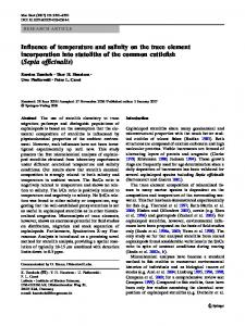
FIG. 5. XRCs of 2-MeV-oxygen-ion-RT-implanted GaAs. The corresponding implant doses are marked in the figure. The crosses are the experimental data. and the solid curves are the simulation by the dynamic model. The strain (solid curves) and damage (dotted curve) profiles as a result of the simulation are plotted aside each XRC.
FIG. 6. XRCs of 2-MeV-oxygen-ion-LT-implanted GaAs. The corresponding implant doses are marked in the figure. The crosses are the experimental data, and the solid curves are the simulation by the dynamic model. The strain (solid curves) and damage (dot curves) profiles as a result of the simulation are plotted aside each XRC.
strain (solid line) and lattice damage (dotted line) given on the right side. We find that the lattice strain and damage in the RT implanted samples (Fig. 5) are distributed more deeply than that in the LT implanted samples (Fig. 6). This result is consistent with the CRBS and SIMS measurements, indicating substantial inward diffusion of both implants and implantation-generated defects in RT implantation. In either case, at low doses, the lattice strain builds up quickly, consistent with lattice damage accumulation revealed by CRBS measurement, with a damage profile following the vacancy distribution as simulated by TRIM. However, in the RT implantation, the strain satu-
rates at a level of 0.4%, starting at the heavily damaged region near the end of range (EOR) of the ions, then extending towards the surface as the dose increases. As a result, a uniform lattice strain field builds up in the entire implanted subsurface region. The lattice damage parameter reaches a maximum level of 0.15 A, which is only 5% of the interatomic distance of the GaAs lattice (2.55 A). Its profile does not change much, which indicates in situ dynamic annealing under this condition. When the dose goes much higher (1 X 10¹⁶ ions/cm2), the lattice strain saturation level increases again to 0.55% at the EOR. This indicates nucleation of high-order defects (such as diva-
2967
J. Appt. Phys., Vol. 69, No. 5, 1 March 1991
Xiong eta/.
2967
Downloaded 16 Dec 2005 to 131.215.225.9. Redistribution subject to AIP license or copyright, see http://jap.aip.org/jap/copyright.jsp
cancies and defect clusters) in that region. In LT implantation, the shallow depth of strain field implies a better spatial confinement of implants and implantation-induced defects, and gives clear evidence of a freeze-in process taking place. The strain saturates at a level of l.O%, at which point a buried amorphization occurs when the radial displacement damage parameter reaches a critical value of 0.6 A, comparable (25%) to the interatomic distance in the GaAs lattice. The amorphous region extends to the surface as the dose increases, and provides a plastic region for strain relaxation. Formation of a continuous amorphous layer was not found in the RT-implanted samples, giving another evidence of in situ dynamic annealing during RT implantation. An interesting result from the best fits to the experimental XRCs should also be noticed; a strain-free surface layer exists in both the LT and RT implanted samples. This can be understood, as we will discuss later, by the concept of rapid defect diffusion and recombination at the surface. III. DISCUSSION In all our investigations of MeV ion implantation into III-V compound semiconductors we have found that the major interaction between MeV ions and lattice atoms in the sample during implantation produces nuclear spikes and electronic spikes.‘7-20 The nuclear spike is induced through ion-nucleus collisions near the EOR of ions. It correlates closely with intensive nuclear energy loss of an ion in the target and causes atomic displacement, resulting in direct structural damage to the lattice. The electronic spike is generated through ion-electron interactions along most of the ion’s path in the sample surface region, resulting in massive ionization and excitation of lattice atoms and kinetic energy loss of the ions. Instead of causing direct structural damage to the lattice, it causes thermal heating and stimulates migration of displaced and implanted atoms, and diffusion and interaction of point defects. Thus, lattice damage processes involved in ion implantation can be classified into two main categories: ( 1) defect generation through nuclear spike damage; and (2) defect diffusion and recombination due to associated electronic spikes and other thermal effects. The final lattice damage state or the defect concentration in the sample after implantation is the result of competition between these two processes. Though the ion-nucleus collision is the primary factor for defect generation, defect diffusion plays a very important role in determining the final defect population and type. In the LT implantation, defect generation by nuclear spikes predominates over defect recombination since the freeze-in effect impedes defect interaction and diffusion. Individual amorphous zones may form along ion tracks and the displaced atoms’s path near the EOR due to the intensive nuclear-spike-induced atomic displacement and fast quenching. An amorphous layer is formed when the individual amorphous zones overlap at a high implant dose (heterogeneous transition). In the case of elevated high temperature (HT) implantation, the processes of defect interaction and recombination overcome defect generation, due to high temperature enhanced defect 2968
J. Appl. Phys., Vol. 69, No. 5,l March 1991
migration and diffusion. In this case a strong in situ transient dynamic annealing occurs, and the zones of large lattice damage are not retained in the sample after implantation.’ The RT implantation can be either of these cases or somewhere between, depending upon the material properties and implantation conditions, such as the beam flux density and the thermal and electrical properties of the target. The result of the RT implantation presented above may fall into the HT implantation category, due to a high diffusion rate of implantation-created defects in GaAs enhanced by MeV-ion-generated electronic spikes in the subsurface region. As a result of defects produced in the implanted layer, lattice strain builds up in the highly damaged region near the EOR and subsequently extends to the subsurface region due to the defects that diffuse in. Lattice strain saturates when defect generation and recombination reach an equilibrium, and a uniform strain field results. In the case of LT implantation, defect interaction and diffusion are inhibited by the freeze-in effect. The damage and strain increase with increasing implant dose until an amorphous layer forms. The top surface remains always strain free in both the LT and RT implanted samples because of the short path for defect diffusion to the free surface boundary. Ion-radiation-induced lattice strain in semiconductor crystals is a highly interesting and important subject in the study of ion damage in ion-implanted semiconductorsespecially in the compound crystalline materials. It is commonly believed that the ion-implantation-generated lattice point defects are mainly responsible for the lattice strain in semiconductor crystals.9-‘1’*8*19*2’-24In general, defect generation in a binary compound crystal is very complicated since the primary point defects (e.g., vacancy and interstitial) are associated with two sublattices. Antisite defects are formed when atoms of one sublattice are placed in sites of the other sublattice (incorrect sites). Other defect complexes and high-order defect clusters can also be formed. However, in a simplified case, during ion implantation the lattice damage nucleation initially involves the production of Frenkel pairs (interstitial-vacancy pairs). Previous studies by Wie et a1.‘27’6*24 of MeV-ion-induced damage effects in GaAs have shown lattice expansion taking place. The model of single ion-lattice collisions they presented24 led to the conclusion that surface lattice strain saturation in MeV ion implanted GaAs was due to an equilibrium defect population by a combination of collision damage, electronic ionization, and dynamic recovery. Considering defect diffusion taking place during implantation, we suggest that the predominant defects in the near-surface disorder region in MeV-ion-implanted GaAs are vacancies and their complexes, which, in turn, lead to lattice spacing expansion or a positive perpendicular lattice strain field build-up in the implantation damaged layer. Normally, the activation energy for self-interstitial diffusion is a few hundred meV, but the activation energy for vacancy diffusion is a few eV. Especially, in the electronic spike damaged region by implantation, interstitial diffusion and annihilation with vacancies and other sinks would be greatly enhanced by electronic ionization and the change of the charge states of the Xiong eta/.
2968
Downloaded 16 Dec 2005 to 131.215.225.9. Redistribution subject to AIP license or copyright, see http://jap.aip.org/jap/copyright.jsp
displaced atoms. Thus, in the implanted layer, especially in the subsurface region, an excess population of vacancies results. The vacancy-dominated defect structure in MeV ion implanted Si crystals has been confirmed recently by Holland et aL2 It has also been observed in keV-ionimplanted GaAs.3 The evidence can also be deduced from our experiment in MeV-ion-implanted GaAs with respect to the very low-level and slowly rising dechanneling yield in the surface damaged region as observed by the CRBS measurement, since vacancies do not give a contribution to dechanneling. With regard to the lattice strain sign in the radiation damaged sample, by examining the characteristics of point defects in a lattice one notes that introduction of a point defect in a crystalline material induces displacements of the lattice atoms that surround it.25326In a vacancy-type defect due to a missing atom in the lattice promotes a negative-U potential with the strength decaying exponentially.2”28 This attractive force field pulls those nearest atoms towards the center of the vacancy. As a consequence, the relaxation of a vacancy induces inward displacements of surrounding lattice atoms limited to a few nearest neighbor shells. The magnitude of the displacement decreases as the neighbor atoms are away from the center of the vacancy; thus, unequal-distance displacements of the neighboring shell atoms result in a lattice spacing expansion, i.e., positive strain. This is the result that we observed in GaAs. It gets more pronounced in RT implantation since implantation-induced electronic spikes greatly enhance interstitial diffusion and recombination, leaving a large population of vacancies in the damaged region. In LT implantation, the freeze-in effect inhibits defect diffusion and drives more efficiently the c-a transition and lattice strain saturation. Interstitials (i.e., displaced atoms) in a damaged crystal produce an opposite strain, as compared to a vacancy. This concept helps us to interpret the negative strain induced in MeV ion implanted InP crystals’7~‘8,20 where In interstitials may be the dominant defect type. IV. CONCLUSIONS The influence of substrate temperature (at RT and LT) on ion-radiation-induced lattice strain field, lattice damage, and amorphization in MeV-ion-implanted GaAs crystals has been studied. We have found that an in situ dynamic annealing process takes place in RT implantation and a freeze-in effect in LT implantation. In RT implantation, ion-irradiation-induced positive perpendicular lattice strain builds up as the defect concentration increases and saturates when defect generation and recombination reach an equilibrium. It involves only weak diffusion of implanted atoms under this condition. Complete amorphization is not observed up to a dose of 2 X 10¹⁶ ions/cm2 in RT implantation. In LT implantation, the lattice strain saturates rapidly as the defect concentration accumulates rapidly with increasing implant dose. The threshold for the formation of a uniform amorphous layer is around 1 X 10’*/cm2 for the conditions used. We have proposed that the lattice strain as an indication of lattice damage is associated with primary defect production which is controlled 2969
J. Appl. Phys., Vol. 69, No. 5, 1 March 1991
by ion-induced spike damage and enhanced defect diffusion. The lattice expansion which causes a positive perpendicular strain in MeV-ion-implanted GaAs is attributed to an excess of vacancies and their clusters.
ACKNOWLEDGMENT This work was supported in part by National Science Foundation (DMR86-15641).
‘See Ion Implantation-Science and Technology, edited by J. F. Zeigler (Academic, New York, 1984); Ion Implantation and Beam Processing, edited by J. S. Williams and J. M. Poate (Academic, New York, 1984). ‘0. W. Holland, M. K. El-Ghor, and C. W. White, Appl. Phys. Lett. 53, 1282 (1988). 3W. Wesch, E. Wendler, G. Gotz, and N. P. Kekelidse, J. Appl. Phys. 65, 519 (1989), and references therein. 4D. K. Sadana, Nucl. Instrum. Methods B 7/8, 375 (1985). ‘S-T. Lee, G. Braunstein, and S. Chen, Mat. Res. Symp. Proc. 126, 183 (1988). 6J. P. Donnelly, Nucl. Instrum. Method 182/183, 553 (1981). ‘5. S. Harris, F. H. Eisen, B. Welch, J. D. Haskell, R. D. Pashley, and J. W. Mayer, Appl. Phys. Lett. 21, 601 (1972). ‘J. R. Cameron, Phys. Rev. 90, 839 (1953). ‘L. C. McDermott, K. W. Jones, H. Smotrich, and R. E. Benenson, Phy. Rev. 118, 175 (1960). “V. S. Speriosu, J. Appl. Phys. 52, 6094 (1981). “B. C. Larson and J. F. Barhorst, J. Appl. Phys. 51, 3181 (1980). ‘*C . R . Wie, T. A. Tombrello, and T. Vreeland Jr., J. Appl. Phys. 59, 3743 (1986). “W. H. Zachariasen, Theory of X-ray Diffraction in Crystals (Wiley, New York, 1945). 14A computer program of TRIM-89 was provided by J. F. Ziegler at IBM, Yorktown Heights, New York. ‘sJ . F Ziegler, J. P. Biersack, and U. Littmark, The Stopping and Range of Ions in Solids, edited by J. F. Zigler (Pergamon, New York, 1985). ‘“C. Y. Wie, Ph.D. thesis, Caltech, 1985 (unpublished). “F. Xiong, C. W. Nieh, D. N. Jamieson, T. Vreeland, Jr., and T. A. Tombrello, Vacuum (Great Britain) 39, 177 (1989). ‘sF. Xiong, C. W. Nieh, D. N. Jamieson, T. Vreeland, Jr., and T. A. Tombrello, Mat. Res. Sot. Symp. Proc. 107, 73 (1988). “F. Xiong, C. W. Nieh, and T. A. Tombrello, Ultramicroscopy 30, 242 (1989). ‘OF. Xiong, Ph.D. thesis, Caltech, 1990 (unpublished). *‘Il. Gonser and B. Okkerse, Phys. Rev. 105, 757 (1957); 109, 663 (1958). 22F. L. Vook and R. W. Balluffi, Phys. Rev. 113, 62, 72 (1959). 23V. S. Speriosu, B. M. Paine, M.-A. Nicolet, and H. L. Glass, Appl. Phys. Lett. 40, 604 (1982). 24C. R. Wie, T. A. Tombrello, and T. Vreeland, Jr., Phys. Rev. B 33,4083 (1986). *‘M. Lannoo and J. Bourgoin, Point Defects in Semiconductors I, (Springer, New York, 1981); J. Bourgoin, and M. Lannoo, Point Defects in Semiconductors II, (Springer, New York, 1983). *‘M W Thompson, Defects and Radiation Damage in Metals (Cambridge University, Cambridge 1969). 27G. A. Baraff, E. 0. Kane, and M. Schluter, Phys. Rev. B 21, 5662 (1980). ‘sP. W. Anderson, Phy. Rev. Lett. 34, 953 (1975). Xiong et al.
2969
Downloaded 16 Dec 2005 to 131.215.225.9. Redistribution subject to AIP license or copyright, see http://jap.aip.org/jap/copyright.jsp