Home
Search
Collections
Journals
About
Contact us
My IOPscience
Influence of typical faults over the dynamic behavior of pantograph-catenary contact force in electric rail transport
This content has been downloaded from IOPscience. Please scroll down to see the full text. 2017 IOP Conf. Ser.: Mater. Sci. Eng. 200 012056 (http://iopscience.iop.org/1757-899X/200/1/012056) View the table of contents for this issue, or go to the journal homepage for more Download details: IP Address: 193.226.9.35 This content was downloaded on 26/05/2017 at 09:19 Please note that terms and conditions apply.
You may also be interested in: LabVIEW application for motion tracking using USB camera R Rob, G O Tirian and M Panoiu Dynamic behavior of elevator compensating sheave during buffer strike S Watanabe and T Okawa Reduced Order Models for Dynamic Behavior of Elastomer Damping Devices B. Morin, A. Legay and J.-F. Deü Modeling the dynamic behavior of turbine runner blades during transients using indirect measurements I Diagne, M Gagnon and A Tahan DICOM supported sofware configuration by XML files Bioing Fabian M Lucena G, Mgr Andrés E Valdez D, Mgr María E Gomez et al. Dynamic Behavior of Lipid across a Micropore during Self-Excited Potential Oscillation Seimei Sha, Takamichi Nakamoto and Toyosaka Moriizumi Modeling and Fault Simulation of Propellant Filling System Yunchun Jiang, Weidong Liu and Xiaobo Hou Application of statistics filter method and clustering analysis in fault diagnosis of roller bearings L Y Song, H Q Wang, J J Gao et al.
Innovative Ideas in Science 2016 IOP Publishing IOP Conf. Series: Materials Science and Engineering 200 (2017) 012056 doi:10.1088/1757-899X/200/1/012056 1234567890
Influence of typical faults over the dynamic behavior of pantograph-catenary contact force in electric rail transport S Rusu-Anghel1 and A Ene2 1
Politehnica University of Timisoara, Department of Electrical Engineering and Industrial Informatics, 5 Revolution Street, Hunedoara, 331128, Romania 2 SC Electrificare CFR SA, Bucharest, Romania E-mail:
[email protected] Abstract. The quality of electric energy capture and also the equipment operational safety depend essentially of the technical state of the contact line (CL). The present method for determining the technical state of CL based on advance programming is no longer efficient, due to the faults which can occur into the not programmed areas. Therefore, they cannot be remediated. It is expected another management method for the repairing and maintenance of CL based on its real state which must be very well known. In this paper a new method for determining the faults in CL is described. It is based on the analysis of the variation of pantograph-CL contact force in dynamical regime. Using mathematical modelling and also experimental tests, it was established that each type of fault is able to generate ‘signatures’ into the contact force diagram. The identification of these signatures can be accomplished by an informatics system which will provide the fault location, its type and also in the future, the probable evolution of the CL technical state. The measuring of the contact force is realized in optical manner using a railway inspection trolley which has appropriate equipment. The analysis of the desired parameters can be accomplished in real time by a data acquisition system, based on dedicated software.
1. Introduction Nowadays, in Romania, each contact line (CL) sector has a maintenance car (Figure 1) for repairs and maintenance activities on 50-60km of CL length. The main goal of this paper consists in proposing for endowment of this maintenance car with a minimal set of measurement elements which permit the identification of the CL real status. 1.1. Establishment of the parameters which influence the energy intake quality In order to establish the geometrical parameters which must be measured, the operating technical conditions of the catenary suspension (Figure 2) were studied and also the Romanian standards. For an appropriate operating functioning, in maximal safety conditions, the catenary suspension must respect the Instruction no. 353 for technical maintenance and reparation of the electrified railway contact line [1]. As a result of the accomplished study, the following geometrical parameters must be measured: - stagger of the contact wire; - height of the contact wire. As well, the followings must be accomplished:
Content from this work may be used under the terms of the Creative Commons Attribution 3.0 licence. Any further distribution of this work must maintain attribution to the author(s) and the title of the work, journal citation and DOI. Published under licence by IOP Publishing Ltd 1
Innovative Ideas in Science 2016 IOP Publishing IOP Conf. Series: Materials Science and Engineering 200 (2017) 012056 doi:10.1088/1757-899X/200/1/012056 1234567890
identification of the dropper absence, their incorrect tensioning or other faulty grip of the CL; - faults location by identification the suspension pillars of the catenary; - geographical location of each measurement set; - movement speed of the maintenance car; - temperature of the environment where the measurements are accomplished. Beside of the geometrical parameters which will be directly measured, the continuous measuring of the pantograph-catenary contact force is imposed because some faults which are mentioned above (dropper absence, faulty grips) can not be identified directly, but only by analyzing the suspension dynamic regime (a new method presented into this paper). -
Figure 1. Maintenance car (VMT 863, SNCFR, București)
Figure 2. General structure of a catenary suspension
2
Innovative Ideas in Science 2016 IOP Publishing IOP Conf. Series: Materials Science and Engineering 200 (2017) 012056 doi:10.1088/1757-899X/200/1/012056 1234567890
Nowadays, the Instruction no. 353 foresaw two measuring types: - measurements accomplished by a „inspection car” [2] (TMC, Plasser UK etc.) which is unique on the railway network which realizes measurements on large time intervals for determining the exactly technical status of the installation. The accuracy of these measurements is very high, but the costs of the inspection car reach millions of Euro. The procedure can not be used for permanently knowledge of the technical status of the catenary suspension, therefore, it does not permit the maintenance based on these measurements. - periodical measurements accomplished at predefined intervals and established by Instruction no. 353 which are manually realized by workers teams. The accuracy of these measurements is subjective and they need the supplying interruption. The costs of these measurements are high due to the stuff expenditure. Neither this procedure does not allow the accomplishing of maintenance operations based on the actual condition of the installations (it is possible that the verified zone has no faults, but these will exist in an unplanned area and will produce effects). From the exposed reasons, in the present paper a new method of the CL maintenance is proposed based on the real status. This status will be determined by automat measurements of the main CL parameters which are established and defined above. The measurements will be realised on short time intervals by daily movement of the maintenance car (existing at each CL sector) for various work. 1.2. Determining of the geometrical parameters influence of the CL over the equipment safety Stagger failure can lead to „hanging” the catenary suspension, contact wire broking, pantograph destroying and also the suspension on hundreds of meter length until the train stops. It follows considerable material damage, disrupting railway traffic, additional costs for restoring the installation [3]. Failure in contact wire height may cause some electric discharge between the contact wire (supplied at 27.5kV) and adjacent elements (works of art, cars, etc.). This electric discharge can cause fire, electric shock, damages of the contact wire. As well the failure in contact wire height may produce variations in the pantograph-catenary contact force, causing direct effect over the quality of the pantograph-catenary energy intake and over the contact elements wear. Poor condition of the droppers produces additional vertical displacement of the contact line and by changing the dynamic behaviour of the catenary suspension it will influence the quality of the energy intake. The same effect has other faults of clamping the contact wire. An improper dynamic behaviour of the catenary-pantograph assembly can cause at high speeds to the cancelling of the contact force and therefore it can lead to the occurrence of the electric arc and adjacent problems (energy faults, premature wear or even melting of the contact wire, electromagnetic pollution). The problem is much treated in the literature ([4], [5], [6], [7]), especially for trains which travel at high speeds, without receiving a radical solution until now.
Figure 3. Electric arc at pantograph-catenary contact [4]
3
Innovative Ideas in Science 2016 IOP Publishing IOP Conf. Series: Materials Science and Engineering 200 (2017) 012056 doi:10.1088/1757-899X/200/1/012056 1234567890
The essential problem in the measurement of geometrical parameters of CL consists in fact that these measurements must be performed from distance, without direct contact with the elements supplied at 27.5 kV voltage. The only methods that are applicable are optical or ultrasonic. 2. Analysis of dynamic behaviour of contact line in case of faults and their identification based on characteristic variations The catenary suspension is a mechanical system with cvasiperiodical composition, consisting mainly of tensioned cables. This structure is very flexible, allowing the propagation of waves of large amplitudes, which are reflected and overlap themselves, generating complex movements. However, by design, catenary contains elements that induce a nonlinear behaviour, which accentuates the difficulties of analysing the behaviour of the forces which act over it. The pantograph, a mechanism with structure composed by articulated bars, presents its own dynamic features and also has a nonlinear behaviour. The dynamic coupling between the two substructures with independent mechanical properties, relative movable to each other, which are linked through a unilateral sliding contact, concentrates a significant number of parameters need to be analysed. As well, the speed of the pantograph is limited up to the values that depend mainly on structural features of the catenary, including technical adjustments necessary for ensuring mechanical tension in the system, and the catenary is considered nowadays as the main limiting factor in the movement of high-speed trains. The problem of mathematical modelling of the pantograph-catenary assembly is very complex and it has been approached by many authors [8-14]. Due to the fact that the stiffness of the catenary is a variable state parameter, dependent on the position of the reference section and it is much lower in regions located toward the middle of the span, as compared with the areas nearby the support pillars, where the catenary is significantly more rigid, it is clear that the dynamic response of the suspension will take effect as the followings: modifying the movement characteristics of the progressive and regressive wave fronts generated by the disturbing action of the pantograph; additional vertical movements, quick and relatively frequent, upward and downward of the pantograph, in order to track the fast movements and variable of the contact wire. Catenary stiffness variation and the cvasirandom frequency of this parameter are recognized as determinant factors of energy intake quality and, therefore, through appropriate design and maintenance, suspension stiffness regularization is followed and decreasing the effect of the presence of the supporting pillars. In terms of the analysis presented and the factors which determine the geometrical and mechanical cvasiperiods in catenary system, they can be classified by various criteria. A classification of interest in the sense issue of this project is the one proposed in [11], which indicates the following two categories: singularities, respectively, faults. a. Singularities - represent catenary areas which not correspond to the nominal intake situation, due to a geometrical and/or elasticity of the catenary. As examples, the followings are mentioned: - Road bridges which permit cars circulation at a level situated above the contact line. Changes induced to the catenary include modifications to the suspension geometry and the characteristics of the cable carrier; - Equipment for mechanical tensioning of the suspension, whose presence requires both major changes to the geometry of the structure overhead, and the existence of an area in which the pantograph must pass on a contact wire on another and, for a certain period of time, it is in contact simultaneously with two or more wires; - Aerial switches. b. Faults – are the result of the wear caused by operational factors, the most known are the followings:
4
Innovative Ideas in Science 2016 IOP Publishing IOP Conf. Series: Materials Science and Engineering 200 (2017) 012056 doi:10.1088/1757-899X/200/1/012056 1234567890
- Broken dropper, eased or missing, which determine the adjusting the contact wire geometry and also the suspension stiffness. These faults are considered as generating of „hard hits” in catenary system. - Flaking or deposits on the contact wire, the presence of junction elements mounted permanently to restore the connection between two wires contact, or during the currents maintenance, which have as effect the changes in the system mass emplacement, with implication over its dynamic characteristics - Breaking or blocking a support arm or other parts or elements, events that have implications over the state parameters, therefore they can greatly affect the dynamic behaviour of the pantographcatenary assembly. In conclusion, the analysis of phenomena that influence the dynamic behaviour of the catenarypantograph in the current electric transport rail involves addressing of complex problems in mechanics of the elastic structures with nonlinear behaviour in connection with the problem in the field of electrical engineering and industrial computer science. 2.1. Determining of the contact force The pantograph-catenary contact force can be determined with the relation (1):
F Ky
(1)
where:
K is global (variable) stiffness of the catenary suspension; y is pantograph movement. The vertical movement of the pantograph can be measured using an ultrasonic distance sensor (Figure 4).
Figure 4. Measuring of the pantograph vertical movement (laboratory equipment) From the considerations presented in the literature [15] and based on the findings of the practical measurements, it follows that the catenary model can be represented by an equivalent resort, with stiffness, K, usually considered constant. In reality, at higher speed of movement of the pantograph, the catenary behaviour is no longer the same, making this characteristic to be variable, [11] and with the behaviour described by the mathematical expressions (2), (3), (4) and ( 5): 2 x K ( x) K 0 1 cos L
5
(2)
Innovative Ideas in Science 2016 IOP Publishing IOP Conf. Series: Materials Science and Engineering 200 (2017) 012056 doi:10.1088/1757-899X/200/1/012056 1234567890
K max K min 2
(3)
K max K min K max K min
(4)
K0
2V K (t ) K 0 1 cos t L
(5)
where:
Kmax – maximal value of the stiffness coefficient between two pillars, Kmin – minimal value of the stiffness coefficient between two pillars, V – pantograph speed of movement, L – distance between two pillars. The variation of the catenary stiffness coefficient for distance between two pillars L = 45m is presented in Figure 5.
Figure 5. Variation of the catenary stiffness coefficient Considering the previous relations, the equivalent functions of the catenary stiffness determined for different values of L are presented in Table 1. The expressions presented in Table 1 for K(x) permit a nonlinear mathematical modelling of the pantograph-catenary system. Table 1. Equivalent functions of the catenary stiffness for different distance between pillars L (m) 40.5 45 49.5 63
K0(N/m) 2435.6 2172 2126.6 1916.7
α 0.1256 0.0823 0.1247 0.1776
K(x) 2435,6(1-0,1256cos0,155x) 2172(1-0,0823cos0,14x) 2126,6(1-0,1247cos0,127x) 1916,7(1-0,1776cos0,1x)
In conclusion, the pantograph-catenary contact force can be experimentally determined by measuring the catenary height and its elasticity coefficient which is calculated. 2.2. Simulations In order to simulate the dynamic behaviour of the catenary suspension-pantograph system, the OSCAR-SAM 5 [16], [17] tool was used. Therefore, a series of faults were express designed for determining of some ‘signatures’ on the obtained signal.
6
Innovative Ideas in Science 2016 IOP Publishing IOP Conf. Series: Materials Science and Engineering 200 (2017) 012056 doi:10.1088/1757-899X/200/1/012056 1234567890
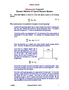
A waveform of the contact force for a dropper fault, designed by simulation is presented in Figure 6. The broken dropper situated on the horizontally axis at 850m and the weakened droppers situated at 958m and 1065m generate important modifying of the signal (increasing of the contact force).
Figure 6. Contact force – OSCAR modelling These simulations will be experimentally verified. Based on them, the exactly faults locating method will be established which influence the dynamic behaviour of the catenary suspension. 3. Conclusions In this paper the parameters which influence the energy intake quality were established and will must be measured for ensuring the maintenance based on the real status of contact line, these being the followings: stagger, contact wire height, contact force and auxiliary parameters: suspension pillars identification, kilometric position, temperature, the maintenance car speed. A novelty consists in fact that the faults determining is proposed (broken or weakened droppers, faulty grips) using an indirect method by analysing the dynamic behaviour of the pantograph-catenary system. The validity of the method was demonstrated by the simulation and in the next step it will be experimentally confirmed. Acknowledgment This work was supported by a grant of the Romanian National Authority for Scientific Research and Inovation, CNCS/CCCDI-UEFISCDI, project number 59BG/2016 within PNCDI III. References [1] MTT-DCF 1972 Instrucția pentru întreținerea tehnică și repararea instalațiilor liniilor de contact ale căii ferate electrificate, Nr.353, Centrul de documentare și publicații tehnice, Romania [2] Ministerul Transporturilor, Construcţiilor şi Turismului 2006 Ordinul nr. 2256/2006 privind aprobarea Instrucțiunilor pentru diagnoza căii și liniei de contact efectuată cu automotorul TMC, Romania [3] Demian D, Rachid A, Gîrniță I, Alic C I, Rusu-Anghel S, Miklos C C and Roșeanu St 2011 Contributions to the Development and Improvement of Maintenance Management of Catenary Networks for Railway, PACIFIC 2011 - International Conference on: PantographCatenary Interaction Framework for Intelligent Control, Conference Proceedings, Amiens, France [4] Ambrósio J, Pombo J, Pereira M, Antunes P and Mósca A 2012 Recent Developments in Pantograph-Catenary Interaction Modelling and Analysis, International Journal of Railway
7
Innovative Ideas in Science 2016 IOP Publishing IOP Conf. Series: Materials Science and Engineering 200 (2017) 012056 doi:10.1088/1757-899X/200/1/012056 1234567890
[5] [6] [7] [8] [9] [10] [11] [12] [13]
[14]
[15] [16] [17]
Technology 1(1) 249-278 Zhang W, Mei G, Wu X and Shen Z 2002 Hybrid simulation of dynamics for the pantographcatenary system, International Journal of Vehicle Mechanics and Mobility 38(6) 393-414 Zhou N and Zhang W 2011 Investigation on dynamic performance and parameter optimization design of pantograph and catenary system, Finite Elements in Analysis and Design 47(3) 288-295 Ritzberger D, Talic E and Schirrer Al 2015 Efficient simulation of railway pantograph/ catenary interaction using pantograph-fixed coordinates, IFAC-PapersOnLine 48-1 pp 061– 066 Alic C, Alic (Miklos) C and Miklos Z I 2009 Upon the Actual Tendencies in Modeling and Simulating the Behavior of the Pantograph-Catenary Pairing Machine Design, Anniversary Volume of the Faculty of Technical Sciences Novi Sad Rob R and Rat C 2013 Mathematical model for studying the variation of the electrical parameters in functioning of nonlinear loads, AIP Conference Proceedings 1558 1345-1348 Collina A and Bruni S 2002 Numerical simulation of pantograph-overhead equipment interaction, Vehicle System Dynamics 38 261-291 Massat J P 2007 Modélisation du comportement dynamique du couple pantographe-caténaire, L'École Centrale de Lyon, France, Doctoral Thesis Rusu N, Averseng J, Miklos C, Alic C and Anghel (Rusu-Anghel) S 2006 Dynamic modeling of pantograph - catenary system for energy loss control, IEEE - TTTC, International Conference AQTR 2006, Cluj-Napoca, Romania Rusu-Anghel S, Gârniţă I, Gavrilă I, Pănoiu C, Pănoiu M and Mezinescu S 2010 Advanced System for the Control of Work Regime of Railway Electric drive Equipment, 6th WSEAS International Conference on Energy, Environment, Ecosystems and Sustainable Development (EEESD 10), Timişoara, Romania, pp 115-121 Rusu-Anghel S, Miklos C, Averseng J and Mezinescu S 2010 Control System for Catenary Pantograph Dynamic Interaction Force, Proceedings of 2010 International Joint Conference on Computational Cybernetics and Technical Informatics (ICCC - CONTI), Timişoara, Romania, pp181-186 Lopez-Garcia O, Carnicero A and Marono J L 2007 Influence of Stiffness and contact modelling on catenary - pantograph system dynamics, Journal of Sound and Vibration 299(4–5) 806-821 ***OSCAR SAM 5.0 – User guide Mitsuo A 2007 Precise Measurement and Estimation Method for Overhead Contact Line Unevennes, Electrical Engineering in Japan 160(2) 77-85
8