Information Model: From Abstraction to Application Jean SCLAVOS - Noëmie SIMONI - Simon ZNATY TELECOM Paris, Département Réseaux 46 rue Barrault, 75634 Paris Cedex 13, FRANCE E-mail:
[email protected] Fax: 33 1 45 89 16 64 Topics: Integrated Management, Models and Architectures. For presentation at the symposium. Keywords: Information Model, SMT.
Abstract Today’s telecommunication structures, already widespread, are based on heterogeneous systems. In fact, in most networks, there are products and services from multiple vendors, and these products incorporate multiple technologies. So how can we manage networks which coexist, cooperate and internetwork in heterogeneous environment? As a matter of fact, we can say that management of network needs to have information on the whole behavior of all network elements. Thus, an information model must be provided, describing the way in which information is structured. We know that this information model is a critical component of a network management framework. Which are the main contributions of network management standards in this area? OSI management standards have adopted the object oriented paradigm for definition of management information [1]. Also, a semi-formal notation for the description of the syntactical elements of managed object classes, GDMO [2], has been defined. In addition, managed object sets (libraries) [3], are provided for developing its own specific information model. However, there is no provision of structuration of the information. On the contrary, CCITT [4] provides a generic network model without distinguishing between network and network element viewpoints [5] and without enhancing the service aspect. However, Network, Network Element and Service views are primordial for integrated management. The Internet community defines the MIB II (Management Information Base) [6]. The information is only attribute oriented. This is mainly for reasons of simplicity and quick provision of an operational network management framework. A main drawback is the lack of powerful modeling concepts. Each standard provides some elements of solution. However they still do not propose an integrated information model. In order to provide a complete answer that meets all requirements, it is necessary to reply to the following questions: Which are the main objectives of a satisfactory management information model? Which are the necessary conceptual tools? The answers lead us to propose an object oriented information model supporting both network and service aspects, which may be applied to any network element according to a particular visibility. To pass from this abstract model to its instantiation for a particular network configuration, we focus on the FDDI subnetwork management. Throughout this application, we enhance its efficiency for monitoring, controlling, analyzing and eventually managing the studied configuration. In addition, we provide the basic rules that guide us during the instantiation of the abstract model for any specific network.
1
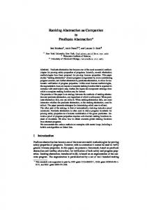
Objectives of an Information Model Administrator
Clients Generic Information Model = Structuration of Management Information Same model for different network elements Networks + Services Information Model Abstract Implementation independent Exhaustive Simple and understandable Applicable to any management level
Management Information Base = Collection of Managed Objects Managed object = Logical representation of a resource MIB 2 MIB 3 MIB 1 MIB 4
ATM Switch
MIB 5
PABX
FDDI DQDB
SERVICES
Ethernet
RESOURCES
Figure 1
• It must structure the information: An information model should describe the way in which information is structured [7]. Also, the amount of information that must be managed for complex network configurations requires a structured approach to be taken [8]. • It must be abstract and generic to model any network element (hereafter NE). In fact many entities in communications and information networks share common characteristics. Abstraction enables to maximize commonalty and minimize implementation efforts. • It must respect the autonomy of each network component. For that, it must be object oriented based. Such an approach also integrates Informational/Behavioral/Computational aspects of each network resource [9]. • It must be implementation independent [10]. • It must be capable of modeling both networks and services. Current models generally consider either network aspects [11] [4] or service aspects [12]. • It must be exhaustive in order to handle any configuration. • It must be simple and understandable in order to easily refine and instantiate it for a particular configuration [13]. • It should be applicable to any management level where decisions may be made. Also, OSI network management standards [14] promote layer management. • It should support the five management functions defined by ISO [15], namely configuration, fault, security, performance and accounting [13]. These objectives lead us to define an object oriented, abstract, recursive and structured information model. This process is done during analysis while implementation aspects are introduced during design. Here we focus on the analysis step only (figure 1). Which are the underlying conceptual tools that should help us to fulfil the above requirements?
2
The conceptual tools • • • •
Network Management Standards Network Protocol Standards Network Interconnection Standards Problem Statement Input
The conceptual tools
• • • •
Abstraction Genericity Recursiveness Management Visibilities Output «The» Information Model Figure 2
The conceptual tools for the construction of our management information model are: • Abstraction • Genericity • Management Visibilities • Recursiveness
1. Abstraction Abstraction is a fundamental way of treating complexity. Abstraction is a means of ignoring the minor differences between network components, situations and processes, and considering only their similarities [16]. Therefore, conceptual frontiers between classes are defined in a rigorous way [16]. Abstraction leads to the definition of a basic set of extensible and reusable classes with minimum number of features. It is the result of observation of the real world. It is considered during the analysis step and is closely related to the problem domain. A good abstraction is one that enhances details important for the user without considering insignificant ones. This approach leads to a simple, understandable and less complex model which, therefore, can be easily applied to any network element and configuration. This is realized through inheritance during the design step which focuses on the solution domain. Abstraction results in classes that represent a common subset of the network elements characteristics. Then these classes need to be completed before being reused. They serve as fundamental components and thus require particular attention to ensure exhaustiveness.
2. Genericity Genericity is another tool for creating reusable classes that can be used to model network elements [17][4]. Like abstraction, it is a feature considered at the analysis step and part of the problem domain. A generic class is one which has one or more parameters representing types [18]. By specializing those types, new classes can be derived. It is essential to understand that abstraction and genericity concepts are not identical. Generic classes are reused by binding their formal parameters, while abstract classes need to be specialized. However, it is often useful to combine these two concepts. Genericity is more difficult to apply since network elements have different characteristics and thus cannot belong to the same class model.
3
3. Management Visibilities Server
Server
Server
Server Cable
Logical data link
GW
LAN 1 GW GW
GW
R
R
R
R
WAN 2 GW R
LAN 2
R
R
R LAN 3
R
WAN 2
GW
R
GW
R
GW
R
B
B WAN 1
WAN 1 Physical level
Data link level
(a)
(b)
Server
Server
Server
Server Application association
Virtual link
GW GW R
R
WAN 2
GW
R
R
GW
R R WAN 1 Network level
WAN: Wide Area Network LAN: Local Area Network GW: Gateway
Application level
(c)
R: Router B: Bridge : Modem, Network Termination
(d)
: PC : Data Base
Figure 3
The Management Visibilities represent the levels at which decisions must be made. According to our observation level, we can perceive the resources of the level observed and possibly those of the lower level. The resources of the observation level are seen as the aggregation of resources of the lower level and the overall service offered at this level is based on the service provided by the lower level. To understand the concept of visibility it is essential to consider the network as a composition of nodes and links. Both are network elements. At the physical level we can observe modems, repeaters, terminations and cables that link them (figure 3a). At the data link level, we can see bridges and logical data links (figure 3b). At the network level, we can distinguish switches, routers and virtual connections (figure 3c). Finally, at the highest level (application layer) we are able to observe only the applications and their associations (between end-systems like servers, PCs, workstations, etc.)(figure 3d). Unlike the OSI model that defines seven layers, we distinguish four levels of visibility. In fact, concepts of layer and visibility level are not identical. A layer may contain several levels and a level may contain several layers. The transport, session, presentation and application layers are mapped onto the application level. The reason for this mapping is that transport, presentation and session layers do not represent levels where particular decisions may be made.
4
4. Recursiveness OSI Layers
Management Visibilities
(K) L a y e r (K-1) L a y e r
(N) Visibility
NE 1
NE 2
(N-1) Visibility
(N-2) Visibility
NE 4
NE 3
NE 5
NE 6
NE 7
(K-2) L a y e r
(N-3) Visibility
NE 8
NE 9
NE = Network Element
NE 10
Figure 4
We have already noticed that the information model should be applicable to any management level where decisions may be made. More precisely, it is applied to each NE at a specific visibility since a management level may be composed of different NEs. This concept reveals the autonomy of the NEs and is consistent with the object oriented approach. Because network elements of different levels are integrated in a containment hierarchy (a network may contain subnetworks which contain network elements etc.), the information model must be recursive in addition to the previous abstraction rule. Application of both recursiveness and abstraction principles enables instantiation of the same model at any level and the obtaining of the basic mapping rules between two adjacent levels. Therefore, recursiveness represents the ability of the same information model to be applied to each level of management visibility and to represent both the different NEs and their containment relationships. The information model that represents a network element at the (N) visibility level may be perceived as an aggregation of the elements of the (N-1) visibility. That means that the operation of the (N) level element is based on the operation of the lower level elements. This principle applies in both network and service parts of the information model. In figure 4 we can see that NE_2 NE is the composition of NE_4 and NE_5 NEs. NE_2, NE_4 and NE_5 belong to the same layer but not to the same level. The abstract information model is applied to every NE and the mapping between adjacent NEs is given by the composition relationships. A more concrete example is an ATM switch ((N) level) which is composed of a number of Virtual Paths ((N-1) level), while every Virtual Path is composed of Virtual Circuits ((N-2) level). All these NEs (switch, Virtual Path, Virtual Circuit) belong to the same layer, namely the ATM layer. However, they are located in three different levels of visibility: the switch level, the VP level and the VC level. The application of the conceptual tools leads us to obtain our abstract information model.
5
The abstract information model
(N-1) Network_Element
(N) Architecture_Element
Software_Element
Management
Entity
Description Type
Description Type
SAP AddrSAP
(N)Architecture_Element
(N)Service
(N-1)Architecture_Elements
(N-1)Service
(iii)
(N) Service
Hardware_Element
Function
Equipment
External Connection Table
Description Type Capacity
NbCurrentEntries NbMaxEntries
(b)
(i)
(N) Network_Element
(ii)
: Composition : 1-1 or 1-0 Relationship : 1-n or 1-0 Relationship
(a)
Flow_Matrix
Abstract_Parameter
Source_Address Destination_Address Nb_PDUs Nb_octets Timer
Current_Value Threshold_Value Conception_Value
Figure 5
Our methodology leads us to define an abstract, object oriented and recursive information model that can represent both networks and services (figure 5a). It is applicable to any network element and to any management level. We represent the model in the figure by using a simple object notation where a rectangle represents an object class: The first part contains the name of the class and the second part its attributes (We reuse the OMT graphical notation [19]). A NE located at the (N) level is characterized by (i) its own architecture ((N) Architecture_Element), (ii) the NEs of the (N-1) level ((N-1) Network_Element) or none if this element is at the lowest level and (iii) the service it must provide to the (N+1) level NEs ((N) Service). This service is in turn modeled by a set of functions. It is essential to understand that every NE aggregates the NEs of the lower level since it depends on them in order to operate. It is obvious that a NE (that is a resource of the network) can be divided into its software and its hardware. It may, be a software entity (i.e. protocol layer), or a hardware entity (i.e. repeater), or both. Therefore the Architecture_Element class is a composition of both Software_Element and Hardware_Element classes. A hardware element is an equipment (modem, machine, etc.). The software of a NE may be the protocol of a layer and may (i.e. FDDI) or may not (i.e. IP) have a management. These protocols provide a service and therefore are characterized by a Service Access Point (SAP). If we consider the NE as a node of the network that implements a protocol, it needs to communicate with other nodes via the network links. The Connection_Table class represents the information concerning the nodes of the same level that can be reached by this NE. The service provided by a network element to the higher level depends on a number of functions (configuration, fault, performance, etc. [15]). These functions are composed of a number of abstract parameters (Abstract_Parameter class) and are associated with a specific flow of data that is represented by the means of a data flow matrix (Flow_Matrix class). This matrix provides to the administrator a detailed view of the traffic associated with a specific NE and, therefore, a better interpretation of the service parameters. We have already noticed that every NE aggregates the NEs of the lower level since it depends on them in order to operate. Thus, the service provided by the (N) level element ((N) Service) depends on its architecture ((N) Architecture_Element), on the service provided by the (N-1) level elements ((N-1) Service) and on their architectures ((N-1) Architecture_Element)(figure 5b). This recursive relationship of the service is applied to any management level and to any NE, and represents a major contribution of our information model. The implementation of any kind of function (QoS, Configuration, Fault, Security, etc.) for a specific NE can be easily and almost automatically developed.
6
FDDI Station and Management Information Base (MIB)
Transmit Data Path
Receive Data Path
SMT frame services RMT Management Operations Agent Notifications Process
LLC
MAC objects
SMT object
MAC SMT
PATH objects CMT
PHY
PORT
PMD (PHY+PMD=Physical Layer)
PORT objects
(b)
FDDI Station
(a)
Figure 6
The Fibre Distributed Data Interface (FDDI) is a network that uses a Token Ring architecture and fiber optics as the transmission medium. It provides a high bandwidth (100 megabits per second) and is used for interconnecting subnetworks, computers and peripheral equipments by establishing connection among hundreds of nodes (stations or concentrators) distributed over distances of several kilometers in extend. Under normal conditions it uses a double ring configuration. In case of fault, the double ring can be reconfigured into a simple ring. The set of FDDI standards includes a «Physical Layer Medium Dependent» (PMD) [20], a «Physical Layer Protocol» (PHY) [21], a «Media Access Control» (MAC) [22] and a «Station Management» (SMT) [23] which specifies the local functions within an FDDI node necessary to manage the FDDI network (figure 6b). The SMT entity is a composition of other functionnal entities including RMT («Ring Management»), that controls the MAC layer, and CMT («Connection Management»), that controls the Physical layer and the configuration of the station. The information available for the management of an FDDI station is defined in the SMT document and is presented using an object oriented concept consistent with the concept used in the OSI Management Standards. Therefore, Station Management information is defined in the form of managed objects (which represent real station resources) within a MIB. Four object classes are defined in the FDDI MIB: The SMT class, which models the information related to the management of an FDDI station as a whole, the MAC class, which models the information necessary for the management of the MAC entities within a station, the PATH class, which represents the information relevant to the internal connection paths within a station, and the PORT class that models the information related to the physical layer entities of an FDDI station (figure 6a). A Managed object is an instance of a Managed object class. A station may have multiple MAC, PATH and PORT objects, but only one SMT object. Every object class contains attributes, supports a number of actions and notifications and is defined using the formats standardized in the ISO 10165/4 (Guidelines for the Definition of Managed Objects) [2]. A PATH interconnects PORTs and MACs within a station. A MAC entity implements the FDDI MAC protocol and handles emission and reception of frames. It provides its services to the higher LLC sublayer. A PORT entity implements both PHY and PMD sublayers and ensures the coding and decoding of symbols as well as their transmission through the optical fiber (figure 6b).
7
The overall structure of the FDDI information model. NETWORK
RING
STATION
Attributes of managed objects: MAC
1) Static 2) Dynamic 3) Functional (a)
: Composition
PORT (b)
PATH
: 1-1 or 1-0 Relationship : 1-n or 1-0 Relationship : 1-2 or 1-1 Relationship
Figure 7
We have instantiated the abstract information model for the following NEs: PORT, PATH, MAC, STATION, RING and NETWORK. The overall model is presented in figure 7b. The PORT and PATH NEs correspond to the PORT and PATH objects respectively of the FDDI MIB. They represent the lowest level of management visibility. The next higher visibility level is MAC. In this level the MAC entities of a station are located. They make use of the service provided by the PATHs and the PORTs in order to be connected to the ring. Therefore, the MAC level aggregates them (composition symbol). In fact, MAC aggregates only the services provided by PORT and PATH. Thus we have a «service composition» and not an «architectural composition». The STATION entity is located at a higher level. Generally, a STATION is considered as the aggregation of all its MACs. This aggregation has, again, mainly a service aspect. That means that in order to operate, a STATION uses the service provided by its MACs. This service is the access to the FDDI ring. However, we should notice that from an architectural point of view, the STATION is a composition («architectural composition») of the MAC, PATH and PORT entities. If the node is a concentrator without MACs, the STATION entity (which represents either a station or a concentrator in FDDI terminology) is the aggregation of the network elements of the lowest level, that is the PORTs and the PATHs. In that case, the concentrator makes use of the connection services provided from PORT and PATH elements in order to attach other stations to the ring [23]. Finally, the NETWORK entity is located at the highest level. It represents the whole FDDI network. However, the NETWORK is not seen just as an aggregation of STATIONs. The existence of the double ring is considered separately, since continuity of the ring is guaranteed (when the optical bypass is implemented) even when stations are disconnected. Therefore, the FDDI network is an aggregation of the stations and the rings. We notice that at the NETWORK level the aggregation has not only service but also architectural aspect. We have, thus, «service and architectural composition». We point out that we consider a network as a set of nodes and links. However, our model provides the link view throughout the «Connection_Table». Thus, instantiation of our abstract information model occurs for nodes only.
A methodology for classifying the attributes of managed objects. During our analysis step we distinguish the attributes of the FDDI MIB according to their nature: static, functional and dynamic (figure 7a). This is an essential task in the overall procedure of the specialization of the abstract model for every NE. Static attributes are initial values concerning the SMT or FDDI protocols and are usually initialized by the administrator. Functional attributes are relevant to the management of a station. They are associated with the functions and state machines implemented by the SMT and correspond primarily to the following elements: error rates, current state of the SMT state machines, and a number of variables and flags that can change during the operation of the SMT. Static and functional attributes are located in the Management class. However, if they are relevant to the SAP or to the connection with other NEs of the same level, they are located in the SAP or Connection_Table class respectively. Dynamic attributes concern the FDDI protocol itself. They reflect the protocol status, change in real time basis and, therefore, are located in the Entity class. Characteristic examples of dynamic attributes are counters of frames. In the remainder of this paper we focus on the instantiation of our information model for all the FDDI NEs.
8
PORT and PATH elements PATH
PORT
Architecture_Element
Software_Element
Architecture_Element
Service
Software_Element
Hardware_Element
Service
Hardware_Element
Equipment
Equipment
Description Type Capacity
Description Type Capacity
PORT_ Equipment PMDClass
Management Description Type
Entity
SAP
Description AddrSAP Type
Connection Table NbCurrentEntries NbMaxEntries
PORT_Management LerCutoff LerAlarm ConnectState PCMState PC-Withhold LCTFail-Ct BS-Flag MACLoop-Time AvailablePaths RequestedPaths My-Type Neighbor-Type Index MACPlacement
Management
Entity
Description Type
Description AddrSAP Type
SAP
Connection Table NbCurrentEntries NbMaxEntries
PATH_Management MACIndicated ConnectionPolicies CurentPath Ler-Estimate Lem-Reject-Ct Lem-Ct EBError-Ct Maint-LS ConnectionCapabilities PC-LS VendorAttribute HardwarePresent LerFlag
TraceStatus RingLatency T-Rmode TVXLowerBound T-MaxLowerBound SbaPayload SbaOverhead SbaAvailable MaxT-Req VendorAttribute Index PATHConfiguration
Function
Flow_Matrix
Abstract_Parameter
Source_Address Destination_Address Nb_PDUs Nb_octets Timer
Current_Value Threshold_Value Conception_Value
Composition 1-1 or 1-0 Relationship 1-1 or 1-0 Relationship 1-1 or 1-2 Relationship Inheritance
Function
Flow_Matrix
Abstract_Parameter
Source_Address Destination_Address Nb_PDUs Nb_octets Timer
Current_Value Threshold_Value Conception_Value
Figure 8 PORT: The instantiation of the abstract model for the PORT element encapsulates all the attributes belonging to the PORT object class of the FDDI MIB (figure 8). A PORT is located in the lowest visibility level. Thus, it does not aggregate other NEs, but provides the basic connection service to the upper layers. All the attributes are either static or functional and, consequently, the Entity class that represents the physical layer protocol (PHY) is empty. Although the PHY sublayer implements a simple protocol for coding and decoding the symbols, the FDDI MIB does not provide relevant information. All the attributes except PMDClass are found in the PORT_Management class. This latter inherits from the Management class. These attributes are relevant to the error rates, the configuration and the current state, and are directly implicated in the CMT (Connection Management) state machines of the SMT. The PMDClass attribute indicates the PMD entity type associated with this PORT and is located in the PORT_Equipment class. PATH: The instantiation of the abstract model for the PATH element encapsulates all the attributes belonging to the PATH class of the FDDI MIB and is located in the same level with PORT (figure 8). PATH and PORT do not aggregate other network elements but provide the basic connection service to the higher level elements (MACs). A Path is a functional entity representing the connections between the MACs and the PORTs within a station. As no protocol is implemented in this NE, its Entity class remains empty. All the attributes belonging to the PATH class of the FDDI MIB are static or functional, related to the CMT (Connection Management) state machines of the SMT and, therefore, found in the PATH_Management class. Notice that our abstract information model is exhaustive. We have considered all the elements required for any configuration. However, during instantiation for a particular NE, all the entities of our model are not systematically specialized.
9
MAC element MAC
PATH
PORT
Architecture_Element
Software_Element
Management
Entity
Description Type
Description Type
SAP AddrSAP
Hardware_Element
Connection Table NbCurrentEntries NbMaxEntries
SAP_MAC MAC_Management AvailablePaths T-Req RequestedPaths T-Max Da-Flag TvxValue UNDA-Flag T-Pri0 DupAddressTest T-Pri1 T-Pri2 Index T-Pri3 hardwarePresent T-Pri4 MA-UnidataEnable T-Pri5 VendorAttribute T-Pri6 FrameErrorRatio RMTState NotCopiedRatio MA-UnidataAvailable DownstreamPORTType FrameErrorThreshold NotCopiedThreshold FrameStatusFunctions BridgeFunctions T-MaxCapability TVXCapability FrameErrorFlag NotCopiedFlag CurrentPath
Service
SMTAddress LongGrpAddress ShortGrpAddress
Equipment Description Type Capacity
MAC Connection_Table UpstreamNbr DownstreamNbr OldUpstreamNbr OldDownstreamNbr
MAC_Entity NotCopied-Ct Late-Ct Error-Ct Frame-Ct Token-Ct RingOp-Ct TvxExpired-Ct Lost-Ct Copied-Ct Transmit-Ct T-Neg
Function
Flow_Matrix
Abstract_Parameter
Source_Address Destination_Address Nb_PDUs Nb_octets Timer
Current_Value Threshold_Value Conception_Value
Composition 1-1 or 1-0 Relationship 1-1 or 1-0 Relationship 1-1 or 1-2 Relationship Inheritance Figure 9
The MAC element is the richest in attributes and represents the information relevant to a MAC entity (figure 9). It encapsulates all the attributes belonging to the MAC class of the FDDI MIB. Moreover, it aggregates the PATH and PORT elements, because it depends on them in order to operate. The MAC_Management class has numerous functional and static attributes relevant to the configuration and management of a MAC entity. Attributes like T-Req and T-Pri0...6 are used in the MAC protocol and are not relevant to the management (SMT) of the station. However, they are found in the MAC_Management class because they are static attributes. On the contrary, all the dynamic attributes are located in the MAC_Entity class which represents the MAC protocol. They all correspond to counters (except T-Neg) and their value changes in real time basis. The SAP_MAC class has attributes corresponding to the addresses of the MAC (individual and group). The MAC_Connection_Table class represents information concerning the addresses of the neighboring MACs in the ring. This is the only information related to the connections between the MACs that is available in the FDDI MIB. However, it is obvious that a MAC entity can reach every other MAC entity that is attached to the ring.
10
STATION and RING elements RING
STATION
MAC
Architecture_Element
Software_Element
Architecture_Element
Service
Software_Element
Hardware_Element
Management
Entity
Description Type
Description AddrSAP Type
SAP
Hardware_Element
Equipment
Equipment
Description Type Capacity
Description Type Capacity
Connection Table NbCurrentEntries NbMaxEntries
Management
Entity
Description Type
Description AddrSAP Type
STATION_Management StationId OpVersionId HiVersionId LoVersionId ManufacturerData UserData ECMState CF-State HoldState RemoteDisconnectFlag MIBVersionId PORTIndexes MACIndexes BypassPresent StationStatus PeerWrapFlag
Service
MAC-Ct NonMaster-Ct Master-Ct AvailablePaths ConfigCapabilities ConfigPolicy ConnectionPolicy T-Notify StatRptPolicy TimeStamp TransitionTimeStamp SetCount LastSetStationId VendorAttrib Trace-MaxExpiration
Flow_Matrix Source_Address Destination_Address Nb_PDUs Nb_octets Timer
SAP
Connection Table NbCurrentEntries NbMaxEntries
Function
Function
Composition 1-1 or 1-0 Relationship 1-1 or 1-0 Relationship 1-1 or 1-2 Relationship Inheritance
Abstract_Parameter Current_Value Threshold_Value Conception_Value
Flow_Matrix
Abstract_Parameter
Source_Address Destination_Address Nb_PDUs Nb_octets Timer
Current_Value Threshold_Value Conception_Value
Figure 10 STATION: The STATION element encapsulates all the attributes belonging to the SMT class of the FDDI MIB (figure 10). These attributes are relevant to both management protocols (that are implemented within a station) and overall configuration of a station. They are either functional or static. Protocols other than those of management are not implemented at the station level. Therefore, the Entity class is empty. Also, the FDDI MIB lacks information concerning the connectivity between stations. Consequently, the Connection_Table class is also empty. Finally, there is no specific SAP defined for a station. A STATION is presented as a composition of its MACs (lower level NEs) and its own Architecture_Element. Indeed, the operation of a station depends on the operation of its MAC entities and its own management protocols. However, in the FDDI context, a STATION element represents, either a station or a concentrator. Unlike a station, a concentrator may not have any MAC entities. Thus, a STATION element in our information model may not encapsulate MAC entities. In such case, it is represented as a composition of its PORTs, its PATHs (the lower level NEs) and its own Architecture_Element. RING: The RING element is not implemented in the FDDI MIB [23]. In fact, the SMT document (which defines the MIB) is restricted to the local management functions of a station. It is clear that this global information is necessary in order to effectively manage an FDDI network. Moreover, the network cannot be seen as a simple aggregation of stations. The reason is that continuity of the double ring is guaranteed (when the optical bypass is implemented) even when stations are disconnected. Thus, RING and STATION entities should be considered separately. Since FDDI MIB does not consider a RING class, the instantiation of our information model does not encapsulate existing MIB attributes (figure 10). Additional information could be, however, inserted into the instantiation of the abstract model in order to better manage the RING entities. Important aspects are, for example, the availability of each of the two logical rings and the MACs that they support.
11
NETWORK element NETWORK
STATION
RING
Service
Architecture_Element
Software_Element
Hardware_Element
SAP
Equipment
Management
Entity
Description Type
Description AddrSAP Type
Connection Table NbCurrentEntries NbMaxEntries
Description Type Capacity
Composition 1-1 or 1-0 Relationship 1-1 or 1-0 Relationship 1-1 or 1-2 Relationship Inheritance
Public domain Manager
Ethernet
Flow_Matrix
Abstract_Parameter
Source_Address Destination_Address Nb_PDUs Nb_octets Timer
Current_Value Threshold_Value Conception_Value
(a)
Private domain Manager
T.R. Manager
DQDB
Function
FDDI Manager
Interconnection
Ethernet
Ethernet Manager
FDDI
Token Ring
Ethernet
(b)
Figure 11
The NETWORK element is a composition of the STATION and RING objects. There may exist one or two RING objects corresponding to the one or two logical rings in an FDDI network. Because the NETWORK entity is not present in the SMT Draft, no attributes of the FDDI MIB are located in the NETWORK class (figure 11a). However, additional information could be inserted in order to better manage the network. The creation of the NETWORK class enables us to obtain the FDDI network global view and to enhance the local management functions of the SMT. In fact, SMT ensures the management of the network through the cooperation of the stations in a totally distributed basis. While this distribution is efficient when applied to a single FDDI network, it is insufficient when interconnecting FDDI with other subnetworks (figure 11b). In such cases, additional operations for completing the management of the interconnections should be developed. These operations should be implemented by a global manager who should interoperate with other network managers throughout a same image of the multi-network component they manage. This image is provided by the information model. In particular, the service component plays a major role. Indeed, the network manager is able to obtain the global operation of its network according to the objects modeling the appropriate service at the subnetwork level. In figure 11b we propose a management organization that can be efficiently combined with our information model. It is the «Hierarchically Distributed Management» [24]. In particular, we consider a manager for each subnetwork (FDDI, Token Ring, Ethernet, etc.). Each of these managers has the network visibility in its information model. Then we create domains of responsibility (private or public), where a service manager controls a set of interconnected subnetworks (a domain). These domain managers interoperate in order to control their interconnections.
12
Conclusion In this paper, we have enhanced the main objectives of an information model and defined the conceptual tools that enable us to reach these objectives. These tools are abstraction, genericity, recursiveness (characteristics of the object concept) and the new concept of management visibilities which correspond to decisions making levels. Then we have proposed an abstract and recursive description of a network component that is able to fulfil any kind of service. This abstract model fills the lacks of the OSI management standards (no structured information model), those of CCITT (no service aspect in their generic model) and those of IAB (no information model, but attribute oriented information). Then we have applied our abstract information model to the FDDI subnetwork. We have primarily structured the several components of the SMT entity. Our analysis permits us to propose some enhancements to the SMT architecture. Two additional visibilities have been justified and adopted: Ring and Network. Network visibility is necessary for integrated management. Then we have instantiated the model to each component of our novel FDDI organization using some basic rules. Finally, we have shown the efficiency of the model in the «Hierarchically Distributed» management organization. A prototype of the model has been developed using the Eiffel language [25][26]. The next step is to carry this realization under the BULL ISM environment [27].
References [1] ISO/IEC 10165/1. Information Processing Systems - Open Systems Interconnection - Structure of Management Information. Part 1: Management Information Model, Aug. 1990. [2] ISO/IEC 10165/4. Information Processing Systems - Open Systems Interconnection - Structure of Management Information. Part 4: Guidelines for the Definition of Managed Objects, Aug. 1991. [3] ISO/IEC 10165/2. Information Processing Systems - Open Systems Interconnection - Structure of Management Information. Part 2: Definition of Management Information, Aug. 1991. [4] CCITT Draft Recommendation M.gnm (M.3100), «Generic Network Information Model», Nov. 1991. [5] C. Enstone. «Generic Information Models for Communications Management», Proc. of the Fifth RACE TMN Conference, Sept. 1991 [6] M. Rose, K. McCloghrie. «Structure and identification of management information for TCP/IP-based internets». RFC 1213, Mars 1991. [7] M. Flavin. «Fundamental Concepts of Information Modeling», Yourdon Press, 1981. [8] S. M. Klerer. «System Management Information Modeling», IEEE Comm. Mag., May 1993, pp 38-44. [9] L. Olson, A. Blackwell. «Understanding Network Management with OOA». IEEE Network Mag., July 1990. [10] M. Sibilla, D. Marquie, Y. Raynaud. «Ensuring Management Systems Interoperability Throughout an Operational Object Model Designing», IEEE Globecom’92, pp1004-1009. [11] H. Yamaguchi, S. Isobe, T. Yamaki and Y. Yamanaka. «Network Information Modeling for Network Management», IEEE NOMS’92, pp 57-66. [12] K. Ohkubo. «Schema Translation into a Unified Model for Service Operation», IEEE Globecom’92, pp1010-1015. [13] T. Liao, D. Seret: «Network Management: Interoperability and Information Model», Computer Comm., April 1991. [14] ISO 10040. Information Processing Systems - Open Systems Interconnection. Systems Management Overview (SMO), June 1990. [15] ISO 7498/4. Information Processing Systems - Open Systems Interconnection. Part 4: Management Framework, 1989. [16] G. Booch. «Object Oriented Design with Applications», Benjamin/Cummings Publishing, 1991. [17] B. Meyer. «Object Oriented Software Construction», Prentice-Hall, 1988. [18] B. Meyer. «Lessons from the design of the Eiffel libraries», Comm. of the ACM, Sept. 1990. [19] J. Rumbaugh, M. Blaha, W. Premerlani, F. Eddy, W. Lorensen. «Object Oriented Modeling and Design». Prentice-Hall, 1991. [20] ISO 9314/3. Information Processing Systems. Fiber Distributed Data Interface (FDDI). Part 3: Token Ring Physical Layer Medium Dependent (PMD), 1990. [21] ISO 9314/1. Information Processing Systems. Fiber Distributed Data Interface (FDDI). Part 1: Token Ring Physical Layer Protocol (PHY), 1990. [22] ISO 9314/2. Information Processing Systems. Fiber Distributed Data Interface (FDDI). Part 2: Token Ring Media Access Control (MAC), 1990. [23] FDDI Station Management (SMT). Draft Proposed American National Standard, June 25, 1992. [24] S. Znaty. «Quality of Service of a High Speed Multi-Network: From a Model to its Realization». Thesis dissertation, 1993 [25] Interactive Software, «Eiffel, The Language», 1988. [26] Interactive Software, «Eiffel, The Library», 1988. [27] «Distributed Management and Security Integrated System Management»: ISM Overview, ISM Operators Guide, ISM Administrators Guide, ISM SML Reference Manual, ISM Application Development Guide, ISM Agent Integrator Toolkit Reference Manual, ISM CM-API Library Reference Manual. Bull, Sept 1992.
13