Shifted Aliased Video Frames. Mohammad S. Alam, Senior Member, .... Illustration of a level 2 microscanning process. Fig. 4. Detector model showing pixels on ...
IEEE TRANSACTIONS ON INSTRUMENTATION AND MEASUREMENT, VOL. 49, NO. 5, OCTOBER 2000
915
Infrared Image Registration and High-Resolution Reconstruction Using Multiple Translationally Shifted Aliased Video Frames Mohammad S. Alam, Senior Member, IEEE, John G. Bognar, Russell C. Hardie, and Brian J. Yasuda
Abstract—Forward looking infrared (FLIR) detector arrays generally produce spatially undersampled images because the FLIR arrays cannot be made dense enough to yield a sufficiently high spatial sampling frequency. Multi-frame techniques, such as microscanning, are an effective means of reducing aliasing and increasing resolution in images produced by staring imaging systems. These techniques involve interlacing a set of image frames that have been shifted with respect to each other during acquisition. The FLIR system is mounted on a moving platform, such as an aircraft, and the vibrations associated with the platform are used to generate the shifts. Since a fixed number of image frames is required, and the shifts are random, the acquired frames will not fall on a uniformly spaced grid. Furthermore, some of the acquired frames may have almost similar shifts thus making them unusable for high-resolution image reconstruction. In this paper, we utilize a gradient-based registration algorithm to estimate the shifts between the acquired frames and then use a weighted nearest-neighbor approach for placing the frames onto a uniform grid to form a final high-resolution image. Blurring by the detector and optics of the imaging system limits the increase in image resolution when microscanning is attempted at sub-pixel movements of less than half the detector width. We resolve this difficulty by the application of the Wiener filter, designed using the modulation transfer function (MTF) of the imaging system, to the high-resolution image. Simulation and experimental results are presented to verify the effectiveness of the proposed technique. The techniques proposed herein are significantly faster than alternate techniques, and are found to be especially suitable for real-time applications. Index Terms—Aliasing, high resolution, image shift, infrared image, Nyquist sampling, shift registration, sub-pixel, Wiener filter.
I. INTRODUCTION
I
N many infrared imaging systems, the detector spacing in the focal plane array is not sufficiently small so as to sample a band-limited scene at twice its highest frequency, resulting in a degraded image due to aliasing artifacts. The construction of a focal plane array with smaller and more closely spaced detector elements is very difficult or may be prohibitively expensive due Manuscript received June 20, 1997; revised April 10, 2000. This work was supported in part under Air Force Contracts F33601-95-DJ0100 and F49620-93-C-0063. M. S. Alam is with the Department of Electrical and Computer Engineering, The University of Alabama, Tuscaloosa, AL 45387-0286 USA. J. G. Bognar is with Technology/Scientific Services, Inc., Dayton, OH 45437 USA. R. C. Hardie is with the Department of Electrical and Computer Engineering, University of Dayton, Dayton, OH 45469 USA. B. J. Yasuda is with the Sensor Technology Branch, Air Force Research Laboratory, Wright-Patterson AFB, OH 45433 USA. Publisher Item Identifier S 0018-9456(00)07023-6.
to fabrication complexity and quantum efficiency problems. The microscan imaging technique increases the spatial sampling rate of an existing focal plane array and reduces aliasing in forward looking infrared (FLIR) imagery [1]–[4]. This process uses multiple spatially undersampled time frames of a scene to estimate a single high-resolution frame. Each undersampled [5] time frame is sub-pixel shifted relative to each other frame, thus providing a unique view of the scene. The frames are then interlaced according to the shifts, to produce the high-resolution image that represents the original scene effectively sampled at a higher spatial sampling rate. The aforementioned process is called controlled microscanning because the subpixel shifts between the temporal image frames are controlled and therefore known a priori [6]. In this paper, we consider a practical scenario where an imager is mounted on a moving and/or vibrating platform, such as an aircraft. Consequently, controlled microscanning cannot be used for such applications. Uncontrolled microscanning is the process where the shifts for each frame are unknown and must be estimated before placing the acquired frames onto a high-resolution grid pattern in order to form a high-resolution image. The shifts for each frame are unknown because they are generated by the random motion and/or vibration of the imager platform and not by a microscan mirror. Using random shifts alone eliminates the necessity for a microscan mirror and a driver system otherwise required in controlled microscanning. Since a fixed number of frames is required for a given level of microscanning, and the shifts are random, the acquired frames will not naturally fall on a uniformly spaced grid pattern. In addition, some of the acquired frames may have almost similar shifts which will create empty bins in the high-resolution image. Thus, the key factors for the high-resolution image reconstruction are the accurate knowledge of the subpixel translational motion of the scene relative to the FLIR array and the accurate estimation of the missing frames (a frame whose translational shifts are similar to another frame or a frame which does not exist corresponding to a desired grid pattern). In this paper, we have utilized a modified version of the algorithms reported in [1] and [7] for estimating the shifts between the acquired frames. Then, a weighted-nearest-neighbor approach is used for estimating the values on the desired uniformly spaced high-resolution grid pattern. Thus, the key factors for the high-resolution image reconstruction are the accurate knowledge of the subpixel translational motion of the scene relative to the FLIR array and the accurate estimation of the image values on the high-resolution grid.
0018–9456/00$10.00 © 2000 IEEE
916
IEEE TRANSACTIONS ON INSTRUMENTATION AND MEASUREMENT, VOL. 49, NO. 5, OCTOBER 2000
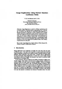
Fig. 1. Block diagram of the imaging system.
An increase in microscan level requires smaller subpixel shifts and produces more frames to interlace. Higher levels of microscanning should produce a proportional increase in resolution of the final reconstructed image. However, attempts at increasing the resolution beyond twice the current sampling rate produce images having the same general appearance independent of microscan level [8]. This bottleneck in the microscanning process was found to be primarily caused by the blurring inherent to the system’s modulation transfer function (MTF) [9]. The main contributors to the system MTF are the optical transfer function and the detector transfer function. Since all parameters of the imager optics and detector array are known, it is possible to accurately model the system MTF representing the system blur function. The application of a Wiener filter [10] has been found to be an effective means of removing the blur caused by the system MTF and improving the resolution of microscanned image data. Note that the Wiener filter restoration is done in the discrete domain on the sensor’s discrete output image. However, the blurring of an image by the optics and detectors of the sensor is a continuous process. Therefore the continuous blurring function must be mapped to a discrete blurring function to be used to create a discrete Wiener filter for restoration [11]. To avoid aliasing in the continuous to discrete conversion of the function, the continuous function must be sampled at a high enough frequency so as to meet the Nyquist rate [12]. Microscanning increases this sampling rate and allows the continuous functions to be properly mapped and used to form the discrete Wiener filter for restoration. A considerable understanding of the advantages and limitations of the Wiener filtering technique was acquired from the information compiled during the microscan simulation. The knowledge acquired from the simulation was applied to restoring imagery collected from a real-time FLIR imaging system. From the simulation and experimental results, it is evident that the proposed technique for high-resolution image reconstruction significantly improves the image quality. In addition, the proposed technique has a relatively low computational complexity, making it attractive for real-time applications. II. THE SAMPLING MODEL In an infrared detector array, sampling is performed by a finite sized array of detectors and three main factors must be taken into consideration: the optical point spread function, the detector charge integration, and the detector array geometry. The block
diagram in Fig. 1 illustrates the sampling process in a FLIR array. In Fig. 1, at first the object scene, denoted , is con, volved with the point spread function of the optics, . and the aperture function for the square detector [6], For our imaging system, we assume the detector has a flat response across its active region so the detector function can be expressed as rect
(1)
where and are the dimensions of the individual detectors. The result is multiplied by a function representing the limited , expressed as extent of the detector array, rect
(2)
and are the dimensions of the array. To apply this where integration to all of the detectors, it is multiplied by the sampling , where lattice, comb comb
(3) and correspond to the center-to-center detector In (3), spacings. Thus, the resulting expression for the staring image is rect rect
comb
(4)
where denotes the convolution operation. An illustration of a uniform detector array showing critical dimensions of detector width, detector spacing and array size is shown in Fig. 2. III. MICROSCANNING PROCESS The microscanning process [2] uses a controlled vibrating mirror to produce a sequence of shifted undersampled frames. Each frame is subpixel shifted relative to each other frame according to a pre-programmed shift pattern. The sequences of frames are then interlaced according to the known programmed shifts to form a high-resolution image which represents the input scene effectively sampled at a higher spatial frequency. This process is called controlled microscanning because the subpixel shifts between the temporal image frames are controlled and
ALAM et al.: INFRARED IMAGE REGISTRATION AND HIGH-RESOLUTION RECONSTRUCTION
917
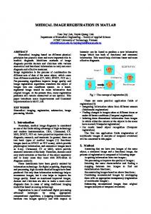
Fig. 2. Detector array.
therefore known a priori. Uncontrolled microscanning results from practical applications where the imager is mounted on a moving and/or vibrating platform, such as an aircraft, and the vibrations associated with the platform can be exploited to create the shifts in the acquired frames. Because the random vibrational shifts are used, the need for a microscan mirror and driver system is eliminated. Thus, the shifts for each recorded frame are unknown and must be determined before an estimate of the high-resolution image can be formed. A level- controlled microscan is defined to be the case staring frames are acquired for each high-resolution where frame, and each staring frame has its own uniquely controlled subpixel shift, each shift being part of a uniform grid. Thus, each staring frame has a shift that is an integer multiple of times the detector width. The staring frames are interlaced pattern to produce a high-resolution frame of in an where is the size of the square detector size array. For a level 2 or 2 2 microscanned image, the original scene is stepped half the length of the detector in the and directions producing a series of 4 staring images. These images are then interlaced to produce the resulting microscan image pixels. Fig. 3 illustrates this process, where of size the reconstructed image has four times the number of unique samples as any of the four staring frames. Thus, a levelmicroscanning effectively increases the sampling frequency by a factor of without changing the detector size or spacing. is small comThe effect of the finite detector array . Nepared to the effects of the detector integration and the , an microscan process can glecting the effect of be expressed as rect comb
(5)
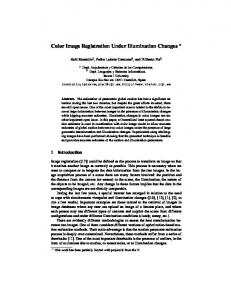
is used to adjust for the reduction in dewhere the factor of microscan steps. Fig. 4 tector integration time at each of the shows the detector model showing pixels on the high-resolution grid that contribute to a low-resolution pixel.
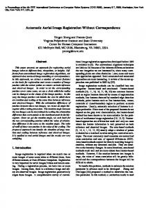
Fig. 3. Illustration of a level 2 microscanning process.
Fig. 4. Detector model showing pixels on the high-resolution grid in (a) that contribute to a low-resolution pixel in (b). In this case, each low-resolution pixel is formed by averaging a 4 4 block of high-resolution pixels.
2
IV. IMAGE REGISTRATION Various algorithms have been reported in the literature for estimating or registering the image shift parameters [1], [7], [8]. Among these techniques, the gradient-based registration technique proposed in [1] appears to be particularly attractive for practical applications. However, this technique only works for shifts on the order of one low-resolution pixel width. To accommodate the case where larger shift values are anticipated, we utilize the iterative technique proposed in [7] and incorporate it with the registration algorithm proposed in [1]. In this algo, is considered to be the rithm, the first acquired frame, reference frame and the shifts of the remaining frames are determined with respect to the reference frame. If represents the and total number of frames acquired by the imager, and represent the shifts in the horizontal and vertical directions for the th frame, then the observed th frame may be expressed as (6)
918
IEEE TRANSACTIONS ON INSTRUMENTATION AND MEASUREMENT, VOL. 49, NO. 5, OCTOBER 2000
where
and for the reference frame, . Considering the first three terms for the Taylor series expansion, (6) may be approximated as (7) Since (7) is an approximation itself and discrete estimates of and must be used, it is useful to apply the method of least and . For squares for solving the registration parameters the least squares solution [9] the error expression
(8) and are discrete variables for must be minimized, where and represent the total number of the and directions, and are the translapixels in the and directions, and tional shifts in the and directions between the th frame and reference frame. Equation (8) can be minimized by differentiand and setting the derivatives equal ating with respect to to zero. This yields two equations that must be solved simultaneously and can be conveniently represented in the matrix form in (9), shown at the bottom of the page. Equation (9) can be represented in a short form as
Fig. 5. Weighted nearest neighbor high-resolution image reconstruction process. The high-resolution grid is formed with respect to the reference frame (o). Three successive frames are shown (+, , *). At each interval, a pixel denoted by (1) is filled using a weighted nearest neighbor approach.
2
TABLE I WEIGHTED NEAREST NEIGHBOR ALGORITHM STEPS
(10a) where (see equation at the bottom of the next page) and
Therefore, the estimated registration parameters can be calculated as (11) (11) To incorporate the case involving larger shift values, we follow the iterative technique of [7]. At first, the initial registration parameters are estimated using (11). The frame is shifted by these estimated shifts so as to closely . The resulting image is then registered to match . Using the above-mentioned procedure, is continuously modified until the registration estimates become
sufficiently small. The final registration estimate is obtained by summing all of these partial estimates. V. HIGH-RESOLUTION IMAGE RECONSTRUCTION After the relative shifts for a sequence of low-resolution image frames are determined, the frames are placed on the high-resolution grid using a weighted nearest neighbor approach. The weighted nearest neighbor algorithm first takes the reference frame and places it on the high-resolution grid at position [0,0]. The successive frames in the sequence must then intervals, where be placed on the high-resolution grid at is the microscan level. Any point on the high-resolution
(9)
ALAM et al.: INFRARED IMAGE REGISTRATION AND HIGH-RESOLUTION RECONSTRUCTION
919
(a)
(b)
(c)
(d)
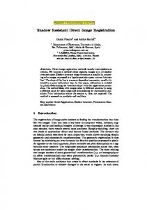
Fig. 6. (a) Continuous opptical MTF. (b) Continuous detector MTF. (c) Continuous system MTF. (d) Continuous Wiener filter.
grid that does not have a corresponding low-resolution frame is filled using a weighted nearest neighbor technique. For each point on the high-resolution grid that must be filled, the three nearest frames are located and given weights inversely proportional to their distance from the desired point on the high-resolution grid. Fig. 5 illustrates this weighted nearest neighbor high-resolution reconstruction process. The weighted frames are then averaged to form the missing frame at that point. Table I lists the steps involved in this weighted nearest neighbor reconstruction process. VI. WIENER FILTERING For most infrared imaging systems, the two main sources of image blurring are the system optics and the finite detector size. An accurate model of these blur parameters can be used to form a Wiener filter which, when multiplied with the Fourier transform of the degraded image, will remove most of the system blur. The Wiener filter is a linear filter that is designed to minimize the mean squared error between a given image and a de-
sired image. The continuous Wiener filter [10], represented by the following:
is
(12) where * denotes the complex conjugate operation, and are the power spectral densities of the noise is the system and original image, respectively, and blur function or Fourier transform of the system point spread function. Since the original image is unavailable and it is and are difficult to characterize the noise, can be approximated by unknown. (13) is a constant representing where the noise-to-signal ratio. The continuous optics and detector MTF’s of our system are shown in Fig. 6(a) and (b) while the continuous system MTF is shown in Fig. 6(c). From Fig. 6(a), it is evident that the optics cutoff at 83.33cyc/mm, and from
920
Fig. 7.
IEEE TRANSACTIONS ON INSTRUMENTATION AND MEASUREMENT, VOL. 49, NO. 5, OCTOBER 2000
(a)
(b)
(c)
(d)
(a) Simulated original image. (b) Low-resolution sampled image. (c) High-resolution output image. (d) High-resolution image with bilinear interpolation.
Fig. 6(b) we observe that the first zero of the detector sinc occurs at 25 cyc/mm. Fig. 6(d) shows the continuous Wiener Filter obtained from (13) using the continuous system MTF shown in is set to 0.01. Notice that the Fig. 6(c) where the parameter optical and detector blurs are both continuous functions acting on a continuous scene. However, the output of the FLIR is a discrete image, and image restoration is done in the discrete domain. Therefore, a discrete Wiener filter that works like a continuous filter must be used to restore the image. The effective discrete filter must have the same frequency response as the continuous filter shown in Fig. 6(d). To successfully map a continuous function to discrete, the continuous function must be sampled at a high enough frequency so as to avoid aliasing in the contin-
uous to discrete conversion of the function [11]. The mapping of the continuous Wiener filter, , to a discrete Wiener is given by filter,
where
and (14)
ALAM et al.: INFRARED IMAGE REGISTRATION AND HIGH-RESOLUTION RECONSTRUCTION
For to operate like system, the spatial sampling interval such that:
921
as a linear must be selected
where
(15)
The above condition truncates the continuous Wiener filter outside the foldover frequencies and prevents aliasing in the discrete version of the filter. The sampling interval is dictated by the detector spacing and microscan level. VII. COMPUTER SIMULATION RESULTS A set of simulated microscanned images was generated from a 512 512 image taken from a digitized photograph, shown in Fig. 7(a). This image was blurred by the system MTF and sampled by a 64 64 detector array where each detector was simulated with an 8 8 kernel which returns the average of all pixels that fall upon it. The resulting low-resolution image is shown in Fig. 7(b). A set of low-resolution images was generated using a random microscan shift pattern. The low-resolution frames were then input into the shift registration algorithm that found the shifts as shown in Fig. 8. Fig. 8 shows both the registered shifts and the programmed shifts for a simulated image set where noise was added to form a signal-to-noise ratio (SNR) of 10. The figure shows that the registered shifts fall very close to the programmed shifts. The mean absolute error (MAE) of the 16 horizontal and 16 vertical registered shifts was approximately 0.05 of a whole low-resolution pixel. From this we conclude that the shift registration technique is very robust with respect to noise. The sequence of low-resolution images and the shift pattern were then input into the weighted neighbor algorithm using a level-4 resolution enhancement. The resulting high-resolution output image, after Wiener filtering, is shown in Fig. 7(c). Fig. 7(d) is a high-resolution image generated from a single low-resolution image using bilinear interpolation such that the size of the high-resolution image as shown in Fig. 7(d) is the same as Fig. 7(c). Comparing Fig. 7(c) and (d), it is evident that the proposed technique yields significantly improved image resolution. VIII. INFRARED FIELD DATA RESULTS For experimental verification of the proposed algorithm, we applied the multiframe registration, reconstruction and Wiener filtering algorithm to data collected on a real-time infrared imaging system. The FLIR camera uses a 128 128 Amber AE-4128 infrared array with a 100 mm focal length f/3 lens. The array uses Indium-Antimonide (InSb) detectors with a response in the 3–5 m wavelength band. The optics are diffraction limited, producing an optical cutoff of 8.33 cycles per milliradian. The system uses square detectors of size 50 m with an 80% fill factor, making the active detector size of 40 m with the remaining 10 microns being inactive. The information about the detector and lens configuration was used in the formation of the system MTF for use in the Wiener filter. A sequence of FLIR image data was collected at the Air Force Research Laboratory at the Wright-Patterson Air Force Base using the above-mentioned Amber imaging system. Three primary targets at a range of approximately 0.9 km are contained in
Fig. 8.
Random shifts associated with the simulated images.
Fig. 9.
Registered shifts of microscanned images.
the image: a military truck, a civilian vehicle, and an M-60 tank. The sequence of infrared frames was input into the shift registration algorithm, and the registered shifts of the microscanned infrared field data set are shown in Fig. 9. Notice that shifts fall in pattern similar to the pattern that was programmed in the a microscanned mirror. From this we conclude that the resignation technique can successfully find shifts in real infrared data. A frame of the infrared sequence recorded earlier is shown in Fig. 10(a). From Fig. 10(a), it is obvious that at this range, the targets in the field are severely undersampled by the detector array. Fig. 10(b) shows the high-resolution image generated from a low-resolution image using bilinear interpolation. The sequence of infrared images and the shift pattern were then input into the weighted nearest neighbor algorithm using a level-4 resolution enhancement. The resulting high-resolution output image, after Wiener filtering, is shown in Fig. 10(c). Fig. 10(c) shows significant increase in image resolution when compared to the low-resolution frames [such as Fig. 10(a)]. Thus, the registration technique, weighted nearest neighbor technique, and Wiener filter-based algorithm proposed in this
922
IEEE TRANSACTIONS ON INSTRUMENTATION AND MEASUREMENT, VOL. 49, NO. 5, OCTOBER 2000
(a)
(b)
(c)
(d)
Fig. 10. (a) Low-resolution infrared field image. (b) High-resolution image with bilinearinterpolation. (c) High-resolution output image. (d) Output using EM algorithm.
paper do work very well on real translationally shifted infrared frames. It may be mentioned that high-resolution infrared images may also be reconstructed from multiple translationally shifted aliased frames using iterative techniques such as the Bayesian approach via the maximum a posteriori (MAP) algorithm [3] or maximum-likelihood approach via the expectation maximization (EM) algorithm [4]. However, each of these algorithms has a high computational complexity, and it may not be possible to implement them in real time using currently available high-performance microprocessors. The EM algorithm, however, has been found to be faster than the MAP algorithm. For comparison purposes, the output image from
the sequence of infrared images using the expectation maximization algorithm [4] is shown in Fig. 10(d). Note that five iterations have been used. Improved resolution may be possible with more iterations, but this will increase the computational burden as well. Based on subjective evaluation, the output of the fast algorithm appears to be comparable to the EM algorithm (using five iterations) for this data set. The implementation of the EM algorithm required 180 million floating operations (FLOPS), as computed by MATLAB. Our implementation of the proposed algorithm required only 18 million FLOPS (i.e., one-tenth of the number of FLOP’s used by the EM algorithm). Therefore, the proposed algorithm appears to be very attractive for real-time applications.
ALAM et al.: INFRARED IMAGE REGISTRATION AND HIGH-RESOLUTION RECONSTRUCTION
IX. CONCLUSIONS We have developed an efficient technique for real-time infrared image registration and high-resolution reconstruction by using multiple frames which are randomly shifted with respect to one another (uncontrolled microscanning). Such translationally shifted image sequences may be obtained by utilizing the random motion and/or vibration of the platform, such as an aircraft, on which the imager is mounted. A registration algorithm for estimating the random translational shifts among the multiple frames has been designed which is found to be inherently suitable for real-time implementation. This algorithm can be used for estimating both noninteger shift values as well as shift values larger than the detector width. However, with uncontrolled microscanning, most of the frames acquired by the imager will have random shift values, and the acquired frames may not fall on a uniformly spaced grid for high-resolution image reconstruction. This problem has been tackled by developing a weighted nearest neighbor approach for estimating the missing pixels and placing them at the appropriate locations on the high-resolution grid. Finally, Wiener filtering has been successfully applied as an effective means of reducing effects of blurring and noise in microscan images caused by the system MTF. The proposed algorithm was tested with both simulated and real infrared imagery. The microscan simulation created a sequence of simulated blurred, randomly shifted and undersampled low-resolution frames. From the simulation results, we conclude that the algorithm can successfully register the shifts and reconstruct an excellent estimate of the original high-resolution image. Comparing the high-resolution output image with the bilinear interpolation version of the low-resolution image, we see a significant increase in the amount of high-frequency information in the image. The knowledge obtained from the microscan simulation was applied to real FLIR data collected on the microscan imaging system. The results of the application of the Wiener filter to the microscan images confirmed the results obtained from the simulation data. It was found that Wiener filtering effectively reduces the effects of blurring and increases image resolution, especially with the real FLIR data. Furthermore, the proposed technique is faster than alternate algorithms and is highly attractive for practical real-time applications. ACKNOWLEDGMENT The authors would like to thank K. Barnard, C. White, E. Armstrong, B. Gualtieri, J. Glidewell, E. Watson, D. Tomlinson, P. McManamon, and D. Cupp for their assistance and support. REFERENCES [1] A. Schaum and M. McHugh, “Analytic methods of image registration: Displacement estimation and resampling,” Naval Res. Rep. 9298, Feb. 28 1992. [2] E. A. Watson, R. A. Muse, and F. P. Blommel, “Aliasing and blurring in microscanned imagery,” in Proc. SPIE, vol. 1689, 1992, pp. 242–250. [3] R. C. Hardie, K. J. Barnard, and E. E. Armstrong, “Joint MAP registration and high resolution image estimation using a sequence of undersampled images,” IEEE Trans. Image Processing, vol. 6, pp. 1621–1633, Dec. 1997.
923
[4] S. Cain, R. C. Hardie, and E. A. Armstrong, “Restoration of aliased video sequences via a maximum-likelihood approach,” in Proc. 1996 Meeting IRIS Specialty Group Passive Sensors, Monterey, CA, Mar. 1996. [5] W. K. Pratt, Digital Image Processing. New York: Wiley, 1992. [6] J. C. Gillette, T. M. Stadmiller, and R. C. Hardie, “Reduction of aliasing in staring infrared imagers utilizing subpixel techniques,” Opt. Eng., vol. 34, pp. 3130–3137, 1995. [7] M. Irani and S. Peleg, “Improving resolution by image registration,” Comput. Vis. Graph. Image Process.: Graph. Models Image Process., vol. 53, pp. 231–239, 1991. [8] E. A. Kaltenbacher and R. C. Hardie, “High resolution infrared image reconstruction using multiple low resolution aliased frames,” in 1996 Nat. Aerosp. Electron. Conf. (NAECON), Dayton, OH, May 1996, pp. 702–709. [9] J. W. Goodman, Introduction to Fourier Optics. New York: McGrawHill, 1996. [10] R. C. Gonzalez and R. E. Woods, Digital Image Processing. Reading, MA: Addison-Wesley, 1992. [11] E. Armstrong, J. Bognar, B. Yasuda, and R. C. Hardie, “The application of Wiener filters to microscan imaging,” in Proc. 1996 IRIS Symp. Passive Sensors, Monterey, CA, Mar. 1996. [12] A. V. Oppenheim and R. W. Schafer, Discrete Time Signal Processing. Englewood Cliffs, NJ: Prentice-Hall, 1989.
Mohammad S. Alam (SM’88) received the B.S. and M.S. degrees in electrical engineering from Bangladesh University of Engineering and Technology, Bangladesh, in 1983 and 1985, respectively, the M.S. degree in computer engineering from Wayne State University, Detroit, MI, in 1989, and the Ph.D. degree in electrical engineering from the University of Dayton, OH, in 1992. From 1992 to 1999, he served as a faculty of electrical engineering at the Purdue University, Fort Wayne, IN, and as a graduate faculty member of both Purdue University and Indiana University. Currently, he is a faculty member of the Department of Electrical and Computer Engineering at the University of Alabama, Tuscaloosa. His research interests include ultrafast computer architectures and algorithms, digital/optical signal and image processing, communication systems, pattern recognition, fiber optics, infrared systems, microprocessor applications, and digital system design. He is the principal author of more than 140 published papers, including 71articles in refereed journals and five book chapters. He served as the editor of the reference book of selected papers on Real Time Optical Pattern Recognition Using Joint Transform Correlation (Bellingham, WA: SPIE: 1999). Dr. Alam is the recipient of the Excellence in Research Award in 1993 and 1997, and the Excellence in Teaching Award in 1995 and 1999, from the School of Engineering and Technology, Purdue University. He has also received the 1996 Researcher of the Year Award and the 1998 Teacher of the Year Award from Sigma Xi—the Scientific Honor Society for exceptional accomplishments in research and teaching, and the 1997 Faculty Colloquium on Excellence in Teaching Award from the Indiana University for distinguished teaching. Most recently, he received the 1998 Outstanding Engineer Award from Region IV of IEEE for his outstanding contribution in research, teaching and service to the profession. He served as a Guest Editor for the JOURNAL OF OPTICAL ENGINEERING (January 1998, May 1998 and May 2000 Issues). His research work has been supported by federal agencies such as the National Science Foundation, Federal Aviation Administration, Air Force Office of Scientific Research, and Wright Patterson Air Force Base as well as by industry such as ITT Aerospace/Communications. He has presented over 30 invited papers, seminars, and tutorials at international conferences and research institutions in the U.S. and abroad. He is a Fellow of the Optical Society of America (OSA), a Fellow of the International Society for Optical Engineering (SPIE), and a member of the American Society for Engineering Education (ASEE) and. He was the Chairman of the Fort Wayne Section of IEEE for 1995–1996.
John G. Bognar, photograph and biography not available at the time of publication.
Russell C. Hardie, photograph and biography not available at the time of publication.
Brian J. Yasuda, photograph and biography not available at the time of publication.