Initial Characterisation of Multiple-Input Multiple-Output (MIMO) Channels for Space-Time Communication D.P. McNamara, M.A. Beach, P. Karlsson & P.N. Fletcher Centre for Communications Research, University of Bristol Queen’s Building, University Walk, Clifton, Bristol, BS8 lTR, UK. E-Mail:
[email protected] The practical realisation of the potentially huge capacities will depend on various factors, none more so than the propagation environment. Published analysis so far has mostly relied on assumptions about the statistical behaviour of this wireless channel. Although this has proven the concept and allowed further investigations to be undertaken, as yet, to the authors’ knowledge, no rigorous MIMO channel measurement campaign has been conducted. Measurements of MIMO channels are therefore necessary in order to characterise the performance of these systems in real environments. This paper describes such measurements and presents the results of initial capacity analysis. Importantly, these measurements have been taken within the coherence time of the channel which ensures that measured decorrelation between elements is due only to multipath fading and not temporal channel variation. The environments examined within this measurement campaign are indoor office and laboratory locations at 5.2GHz. These should exhibit a high degree of scattering and allow investigation of the suitability of space-time communication techniques for proposed/future Wireless LAN standards such as HiperLAN/2.
Abstract Recent theoretical studies have demonstrated the substantial capacity or diversity gains possible when multi-element arrays are employed at both a transmitter and receiver. This is only possible when the radio channel exhibits suficient scattering to induce independent fading at each receive element. An appreciation of both the temporal and spatial variation of such Multiple-input, Multiple-Output (MIMO) channels is therefore required in order to investigate the performance of this architecture in real environments. In this paper we present initial results from indoor MiMO channel measurements taken within the coherence time of the channel. It is shown how capacity analysis of the MIMO channel response matrix alone can be misleading and how the combination of the variation of this with signal to noise ratio in real environments is particularly important.
1. Introduction As recently reported in the literature [ 11, the traditional smart antenna concept can be extended by employing multi-element arrays at both ends of the communication link in order to create a multiple-input multiple-output (MIMO) channel. It has been shown analytically that when deployed in a suitably rich scattering environment, this architecture is capable of greatly increasing the spectral efficiency of such a system [2]. It is this feature in particular that has aroused much interest in applying MIMO techniques to future wireless communication standards in order to help meet the anticipated demand for high bit-rate, real-time services within limited bandwidths. Several architectures have been proposed to exploit MIMO channels. Diagonal and Vertical BLAST (Belllaboratories LAyered Space-Time) have been shown to achieve very high spectral efficiencies 1][3], whereas Space-Time Coding provides a means of obtaining a vastly increased diversity order and coding gain [4].
0-7803-6507-0/00i$10.00 02000 IEEE
2. MIMO channel capacity When a transmitter employs an nrelement array, it can be seen intuitively that maximum spectral efficiency will be achieved if all n T elements transmit independent bit streams in the same bandwidth. Successful reconstruction of these signals relies upon there being sufficient multipath scattering to achieve independent fading between each of these transmit elements and each of the nR-elements(where nR 2 nr) at a receive array [ 13. This can be represented mathematically as a system of simultaneous equations. Expressed in matrix form, the nRdimensional received signal vector, r, is given by
r=Hs+v
1193
(1)
VTC 2000
where s is the nrdimensional vector of transmitted symbols, H is the complex nR-by-nr channel response matrix and v is the noise vector. Given a suitable signal to noise ratio and knowledge of H at the receiver, the performance of this system will therefore be dependent on the properties of H. In order to fully reconstruct the transmitted signals, H must be full column rank. In practise this will be achieved when the requirement for independent fading is satisfied. Depending on the degree of decorrelation between the received signals, the information theoretic capacity of this MIMO channel will vary. It has therefore been shown [ 2 ] that the usual Shannon capacity equation of
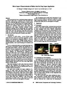
MIMO channel sounding is achieved through the use of additional switching and synchronisation circuitry to control a second eight element uniform linear array at the transmitter (Figure 1b). The initial results presented here employed simple monopole elements, half-wavelength spaced, to form this array so as to retain an omnidirectional radiation pattern and therefore excite as much scattering as possible within the indoor environment.
for single-input single-output (SISO) systems can be extended to take account of MIMO channels and becomes
a) RXarray
where H is the nR by nT complex channel matrix ( H i jis the normalised transfer function from transmit element j to receive element i), nT and nR are the number of transmit and receive elements respectively, p is the average signal to noise ratio at each receiver branch, I is the identity matrix, det is the determinant and * is the complex conjugate transpose. The channel response matrix, H , is normalised so as to remove the path loss component and only show the relative variation in the path responses between all nRxnT elements. The ideal conditions for achieving high capacity MIMO communications are typified by indoor environments since these generally exhibit a high angular spread in the scattered signals arriving at the receiver [ 5 ] . This should ensure a high probability of achieving independent fading between all the elements, and hence the selection of environment for consideration here.
b) TXarray Figure 1: Antenna arrays employed for 5.2GHz MIMO channel measurements For each transmit element in turn, a vector snapshot of the channel is taken at the receiver. In this way, eight consecutive vector snapshots contain the complex channel responses of all 64 combinations of the eight transmit and receive elements. This allows a full ‘MIMOsnapshot’ of the channel to be recorded in 1 0 2 . 4 ~ well within the coherence time of an indoor channel. Furthermore, up to 16 MIMO snapshots can be recorded back-to-back with no delay, thus enabling analysis both within the channel coherence time and the HiperLAN12 frame period [7]. Although wideband data is recorded, the results presented here only consider a subset of this data in order to analyse the narrowband channel response in common with theoretical analysis [2]. Measurement time accuracy is assured through the use of Rubidium referenced clocks at both transmitter and receiver, with an optical fibre connection to provide synchronisation and absolute phase stability. A back-toback system calibration also accounts for amplitude and phase distortions in the hardware. Further calibration is conducted on the receive array to compensate for mutual coupling effects when conducting direction of arrival estimation. Details of the system verification trials and measurements can be found in [8].
-
3. Hardware description The measurement platform used for these measurements is based on a Medav RUSK BRI vector channel sounder [ 6 ] .This employs a periodic multi-tone signal with a maximum bandwidth of 120MHz, centred at 5.2GHz. The receiver incorporates a uniform linear array composed of eight dipole-like elements, each having a beamwidth of 120° (Figure la). A fast multiplexing system switches between each of these elements in turn in order to take a full ‘vector snapshot’ of the channel in 12.8~.
0-7803-6507-0/00/$10.00 02000 IEEE
1194
VTC 2000
4. Indoor environments
high degree of scattering. This is confirmed in Figure 3 which shows a received delay-azimuth plot for one of the transmit elements. This scattering produces an rms angular spread of 7' giving the resultant decorrelation between received signals.
Initial measurements were conducted with the receiver placed at a fixed location in a typical large open plan office. The array was positioned at a height of 2.2m and oriented so that coverage of most of the room was obtained. The transmitter location was varied so as to give both line-of-sight (LOS) and non line-of-sight (NLOS) conditions, with its array at a height of 1.lm. As expected, the multipath scattering in NLOS locations creates a high degree of decorrelation between signals at each receive element as can be seen in Figure 2a. Evaluating equation (3) for this channel response matrix and an arbitrary signal to noise ratio of 16dB, we obtain a capacity of 27.7bitslslHz.
__ 40
h7
L ;a E
P
-20 40
Figure 3: Delay-Azimuth spectrum for a LOS channel The effect of the more deterministic propagation in the
LOS case is demonstrated by the reduction in the peak variation of path gains from 19.6dB for the NLOS case to 10.ldB for LOS. This also has an effect on the capacity (calculated as before), reducing it to 17.9bits/s/Hz. Even 8
so, the advantage of the MIMO architecture is still apparent when compared with the capacity for a singleinput single-output system which, for the same arbitrary signal to noise ratio of 16dB yields a capacity of only 5.3bits/s/Hz (equation 2). Although only two specific examples have been presented here, these have been selected as being typical for LOS and NLOS locations among the measurements recorded in this environment. A further measurement trial was conducted with a mobile transmitter in a large laboratory, half of which is shown in Figure 4. With the receive array positioned half way along one wall and oriented so as to only cover one end of the room, the transmitter was pushed at a constant speed along the length and out of the end of the room. This created the scenario where the propagation path changed from NLOS to LOS and back to NLOS.
Tx Antenna
RX Antenna
a) NLOS
lX Antenna
RXAntenna
b) LOS
Figure 2: Normalised narrowband MIMO channel magnitude responses for NLOS and LOS conditions When compared with the NLOS case, the LOS channel response shown in Figure 2b can also be seen to be subject to significant variations and therefore a relatively
0-7803-6507-0/00610.00 02000 IEEE
Figure 4: Laboratory measurement environment
1195
VTC 2000
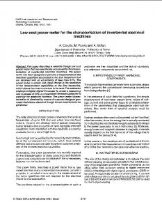
The spatially averaged signal to noise ratio (SNR) shown in Figure 5a was calculated from the measured path loss and an assumed transmit power and noise power at the receiver. These were chosen to scale the S N R to reasonable values. The trend varies as expected for the changes from NLOS to LOS and back again with the large variations away from this trend being due to the transmitter passing behind the pillars shown in Figure 4. Figure 5b shows the variation in MIMO channel capacity (equation 3) for a fixed S N R of 16dB. The trend can be seen to drop as the propagation becomes more deterministic where LOS exists. Variations from the general trend are again noticeable as the transmitter passes a pillar, leading to brief increases in capacity during these NLOS periods. It can again be seen that even though the capacity reduces in LOS conditions, it still remains significantly higher than that which could be achieved using conventional communication techniques. These results are consistent with those previously presented as they show that for a fixed S N R , the MIMO channel capacity varies according to the degree of decorrelation between the received signals which, in turn, is dependant on the propagation environment. In contrast to this, Figure 5c shows how the MIMO channel capacity really varies when the true SNR values (Figure 5a) are used in the calculation. It can clearly be seen that this overall capacity trend is dominated by the SNR variation. The movement of the transmitter from a NLOS to a LOS position is therefore actually beneficial to the MIMO channel capacity since the detrimental effect of increased correlation between the received signals is outweighed by the beneficial effect of greater SNR. Any future analysis of MIMO channel capacities should therefore take account of this relationship between S N R and received signal correlation. It is intended that further analysis of these results should yield a suitable channel model for this purpose.
The channel sounder was set to record 16 consecutive snapshots of the MIMO channel (measurement time of 1.63ms), once every second. This accounts for the stepped appearance of the plots in Figure 5 since each block of 16 snapshots are taken within the coherence time of the channel. The characteristics are therefore stationary within a block but change from one to the next. I
25,
I
im
Oo
m
300
4m
mo
500
1
Snspshol
a) Spatially averaged signal to noise ratio
I
st 01
o
1
m
m
m
4
m
m
6
o
o
I
Snapshot
b) MIMO channel capacity for fixed SNR of 16dB 40 r
1
5. Conclusion We have reported the initial results of an indoor MIMO channel measurement campaign in which the channel responses have been recorded within the coherence time of the channel. It has been shown that in indoor environments even line of sight conditions exhibit sufficiently high scattering to generate large MIMO channel capacities. The effect of SNR variation has also been demonstrated to have a significant effect on the channel capacity. This outweighs the effect of the corresponding change in received signal correlation between due to the changing propagation environment. The creation of a channel model that reflects this relationship is therefore required.
".i"-u $15
1 Oo
la
m
300
4m
yo
1 Em
1
Snapshol
c) MIMO channel capacity for true SNR Figure 5 : Channel measurements for a mobile TX moving from NLOS to LOS and back to NLOS
0-7803-6507-0/00/$10.00 02000 IEEE
1196
VTC 2000
6. Acknowledgements
[3] P.W. Wolniansky, G.J. Foschini, G.D. Golden, R.A.
The authors gratefully acknowledge the financial contribution of the UK EPSRC and the DERA for their support of this work and to HEFCE for their support in the procurement of the Medav RUSK system under
[4]
JREI’98. Finally, we especially wish to thank Walter Wirnitzer and Dirk Bruckner of Medav GmbH for their significant help with the customisation of the channel sounder.
[5]
7. References
[6] [7]
[ I ] G.J. Foschini, “Layered Space-Time Architecture for Wireless Communication in a Fading Environment When Using Multiple Antennas”, Bell Labs. Tech. Joumal, Vol I , NO 2, Autumn 1996,pp. 41-59. [2] G.J. Foschini and M. J. Gans, “On Limits of Wireless
[8]
Communications in a Fading Environment When Using Multiple Antennas”, Wireless Personal Communications, Volume 6, No. 3, March 1998, p. 31 1-335.
0-7803-6507-0/00/$10.00 02000 IEEE
Valenzuela, “V-BLAST An Architecture for Realizing Very High Data Rates Over the Rich-Scattering Wireless Channel”, Proc. ESSE-98, Pisa, Italy, Sept. 29, 1998. V. Tarokh, N. Seshadri, A.R. Calderbank, “Space-Time Codes for High Data Rate Wireless Communication: Performance Criterion and Code Construction”, IEEE Trans. on Information Theory, V o l a , No 2, March 1998, pp. 744-765. Karlsson P., Berglijung C., Bojeson H. & Pamp J., “Analysis and results of wideband spatial radio channel measurements at 5GHz - Impact on multiple antenna systems”, AP2000, Davos, 9-14 April 2000. http://www.medav.de HIPERLANl2, DLC Specification, DTSIBRAN0020004-1, October 1999, V0.m. M.A. Beach, D.P. McNamara, P. Karlsson & A.R. Nix, “Development of a Channel Measurement System for Multiple-Input Multiple-Output (MIMO) Applications”, Accepted for publication, IST Workshop, October 2000.
0 British Crown Copyright, 20OODERA Published with the permission of the controller of Her Britannic Majesty’s Stationery Office
1197
VTC 2000