11 Professor, Department of Aeronautics and Astronautics, Room 37-327, AIAA ... OW that 40 years have passed since Apollo 11 first landed on the Moon â a ...
AIAA 2009-6713
AIAA SPACE 2009 Conference & Exposition 14 - 17 September 2009, Pasadena, California
Initial Development of an Earth-Based Prototype for a Lunar Hopper Autonomous Exploration System Phillip M. Cunio1, Alessandra Babuscia2, Zachary J. Bailey3, Hemant Chaurasia4, Rahul Goel5, Alessandro A. Golkar6, Daniel Selva7, Eric Timmons8 Massachusetts Institute of Technology, Cambridge, MA, 02139 Babak E. Cohanim9 Draper Laboratory, Cambridge, MA, 02139 Downloaded by JET PROPULSION LABORATORY on July 2, 2015 | http://arc.aiaa.org | DOI: 10.2514/6.2009-6713
and Jeffrey A. Hoffman10, David W. Miller11 Massachusetts Institute of Technology, Cambridge, MA, 02139
MIT is developing an Earth-based hopper prototype for autonomous planetary exploration. This paper describes the initial development of the hopper prototype and its application as a testbed for lunar hopper technologies. The prototype hopper consists of a gravity-canceling system, composed of battery-powered electric ducted fans, and an integrated lunar hopper system, which operates using cold gas propulsion. The gravitycanceling system is designed to allow the lunar hopper system to operate in an environment which is dynamically similar to the surface of the Moon, although it also allows for recovery and safe touchdown if the cold gas system experiences a failure. The environment provided by the electric ducted fans applies the fan thrust against Earth’s gravity to obtain a desired upward acceleration, allowing the cold gas jets to operate as if they were in a fractionalgravity environment. The key design features of the integrated gravity-canceling and lunar hopping systems are presented in this paper.
1
Graduate Research Assistant, Department of Aeronautics and Astronautics, 77 Massachusetts Avenue, Room 31222, AIAA Student Member. 2 Graduate Research Assistant, Department of Aeronautics and Astronautics, 77 Massachusetts Avenue, Room 33208. 3 Graduate Research Assistant, Department of Aeronautics and Astronautics, 77 Massachusetts Avenue, Room 33208. 4 Graduate Research Assistant, Department of Aeronautics and Astronautics, 70 Vassar Street, Room 37-442, AIAA Student Member. 5 Graduate Research Assistant, Department of Aeronautics and Astronautics, 77 Massachusetts Avenue, Room 33409, AIAA Student Member. 6 Graduate Research Assistant, Department of Aeronautics and Astronautics, 77 Massachusetts Avenue, Room 33409, AIAA Student Member. 7 Graduate Research Assistant, Department of Aeronautics and Astronautics, 77 Massachusetts Avenue, Room 33208. 8 Undergraduate Student, Department of Aeronautics and Astronautics, 77 Massachusetts Avenue, Room 33-208. 9 Senior Member of the Technical Staff, Space Systems, 555 Technology Square MS 27. 10 Professor of the Practice, Department of Aeronautics and Astronautics, Room 37-227, AIAA Member. 11 Professor, Department of Aeronautics and Astronautics, Room 37-327, AIAA Senior Member. 1 American Institute of Aeronautics and Astronautics Copyright © 2009 by the authors. Published by the American Institute of Aeronautics and Astronautics, Inc., with permission.
I. Introduction
Downloaded by JET PROPULSION LABORATORY on July 2, 2015 | http://arc.aiaa.org | DOI: 10.2514/6.2009-6713
N
OW that 40 years have passed since Apollo 11 first landed on the Moon – a project in which engineers, faculty, and alumni from MIT played major roles in the development and operation of the lunar lander, especially its guidance and navigation computer and algorithms1 – interest in exploring the Earth’s closest neighboring planetary body has grown again. Today, MIT is once again working on landing vehicles on the Moon for science and exploration. Efforts by NASA have humans landing back on the moon as early as 20192, but before those astronauts return, much of the groundwork for science and exploration will be laid by the next generation of robotic explorers. Both NASA and the private sector are developing vehicles to foster this exploration. In the context of the Google Lunar X-Prize (GLXP), a $30 million competition for the first privately funded team to send a robot to the moon, traverse 500 meters, and transmit video, images, and data back to the Earth. MIT, as part of the Next Giant Leap team (http://www.nextgiantleap.com/team.html), is developing an Earth-based hopper prototype to test GNC and operational modes of a hopper system for planetary exploration. The prototype is called TALARIS, for Terrestrial Artificial Lunar And Reduced gravIty Simulator. The TALARIS testbed provides a hardware-in-the-loop system to verify and validate algorithms and operational concepts, gain experience building and operating a hopper for planetary exploration, and demonstrate a real-time system in a representative environment. This paper describes the testbed under development for lunar exploration, and with potential extensibility to other planetary environments. Autonomous hopping systems are enabling technologies for the remote exploration of planetary bodies. Although rovers are limited in the types of terrain they can successfully traverse, hoppers are terrain-independent. With proper autonomous guidance, hoppers can become successful tools for remote exploration of planetary bodies, operating scientific payloads and laying the groundwork for human presence. Earth-based testing can be used to buy down the technical and operational risks by affording an operational environment that is risk-tolerant and accessible to humans, as well as flexible enough to incorporate different elements of software and hardware.
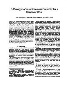
II. Concept of Operation The TALARIS hopper prototype is designed to simulate operations in an environment dynamically similar to that of the Moon. To simulate this hypogravity environment, a support system composed of four Electric Ducted Fans (EDFs) is used to remove 5/6ths of the Earth’s gravitational influence. The remaining 1/6th gravity is counteracted by means of a cold gas satellite emulator (CGSE) system that functions as the analogue to the actual lunar hopper, responding to the environmental dynamics as it would on the Moon. Once the EDFs are operating in a steady state, the cold-gas system on TALARIS experiences 1/6-g acceleration, providing a lunar environment test platform. The concept of operation for the TALARIS hopper is illustrated in Figure 1. The flight profile is constrained to a two-dimensional profile in order to reduce the operational risk and allow an incremental development of functionality in the system. The flight profile of TALARIS is composed of three phases. In Phase 1, the vehicle takes off by operating the EDFs in a steady state 5/6-g flight mode, and operating the CGSE system to provide 1/6-g vertically plus the required acceleration for a controlled ascent to the operational altitude of 2 m. In Phase 2, the vehicle performs a straight and level flight of 30 m. In Phase 3, the reverse of Phase 1 is performed to fly a controlled descent and landing to the ground.
Figure 1. Dynamically-similar hopping distances.
2 American Institute of Aeronautics and Astronautics
The total impulse delivered by a cold-gas system cannot match the total impulse delivered by an actual hydrazine system, but equivalence can be made by accounting for the difference in total impulse delivered for a given total propulsion system mass3. Using such a comparison, a hydrazine-powered 500-meter hop on the Moon (which is the traverse distance required to win the Google Lunar X-Prize competition) maps to a cold-gas-powered 30-meter hop on Earth. The Earth-based flight profile is intended to replicate as nearly as possible the lunar flight profile, by creating similar forces and accelerations to those that will be experienced on the Moon. During the flight, the CGSE system feels only the 1/6th of Earth’s gravity that is not counteracted by the EDFs, and thus operates in an environment roughly analogous to that of the Moon.
Downloaded by JET PROPULSION LABORATORY on July 2, 2015 | http://arc.aiaa.org | DOI: 10.2514/6.2009-6713
III. Hopper Prototype Subsystems This section describes the subsystems constituting TALARIS in its current implementation. The goal of the prototype system is to enable testing of hopping guidance algorithms and propulsion hardware in a relevant dynamic environment, while safely operating in proximity to humans and groundside laboratory facilities, which enables rapid repair and refurbishment. The prototype vehicle has been built to the extent of the major bus subsystems – only the cold gas satellite emulator system has not been integrated into the vehicle yet. A. Structure The structure of the TALARIS hopper is designed to withstand a drop from 2 meters while supporting the 4 EDFs that provide the 5/6-g canceling force, provide a deck onto which all other components can mount, and provide the capability for mounting two nitrogen tanks and the remainder of the CGSE system hardware. Materials were selected for machinability, light weight, and low cost. Most of the structural elements are made of 6061 aluminum alloy. The nitrogen tank mounts are made of nylon. The deck is made of polycarbonate, and the landing feet are made up of polyurethane. The primary considerations that guided the design were that the structure should be lightweight, modular, cost effective, and easy to manufacture at MIT’s machine shop. The total weight of the structure is 5.7 kg. For attitude control stability, it was desirable to mount the EDFs at angles canted 15 degrees from the vehicle’s vertical centerline rather than pointing straight upwards. For this purpose, the EDF support bracket provides a compound mounting angle. In order to accomplish this, one piece creates an angle from the vertical axis in the first lateral direction. Then another piece, mounted to the first angle, creates the second 15-degree angle. The compound angle structure is shown in Figure 2. Figure 3 shows the primary structure with all completed Figure 2. Compound angle design. components attached. The vehicle envelope is 65 x 70 x 50 cm. The feet, which consist of an orthogonal rib Electric Ducted structure, are designed to mitigate the impact of a Fans (EDFs) x 4 Lithium polymer Laser landing on any number of legs (the worst case batteries x 10 Altimeter being 1 leg). Contact cement was used to mate pre-cut pieces into a three-dimensional shape EDF motor On-board computer controllers x 4 with increased buckling resistance. The feet (Dell Mini-9) delaminate during a crash landing rather than Shock tearing or ripping, which increases reusability. Absorbing Aluminum 6061 Several constraints were taken into Rubber Feet structure consideration when designing the component layout on the deck of the vehicle. The first, and Inertial Measurement Unit (IMU) most important, was the mass of the individual Figure 3. Primary structure with EDFs, landing gear, components. The batteries were positioned in the and avionics. center because they are the heaviest single component. The rest of the components had to be laid out as symmetrically as possible, in terms of mass, in order to bring the center of mass as close to the geometric center as possible. The components also had to be laid out in specific groups depending on how they interacted with each other. Figure 4 shows the actual vehicle with most of the avionics integrated onto the structure. Note that the on-board computer and altimeter are also integrated, although they are obscured by the batteries.
3 American Institute of Aeronautics and Astronautics
Laser Altimeter
Lithium polymer batteries x 10
Downloaded by JET PROPULSION LABORATORY on July 2, 2015 | http://arc.aiaa.org | DOI: 10.2514/6.2009-6713
EDF motor controllers x 4
EDF mounts x 4
Fuse, shutdown button, and contactor safety switch
Inertial Measurement Unit (IMU)
Figure 4. Vehicle with avionics integrated onto structure. B. Propulsion The propulsion subsystem for the TALARIS vehicle is partitioned into two functional subgroups: an airbreathing electric ducted fan (EDF) system designed to offset 5/6ths of Earth’s gravity, and a cold gas satellite emulator system designed to simulate impulsive hydrazine propulsion, as would actually be used on the Moon. The locations of these two propulsion elements are highlighted in a model of the vehicle shown in Figure 5. The details of the CGSE system are expanded in Section G of this paper. The key goals for the propulsion system design were to provide sufficient thrust for the 30-m powered hop, provide forces and torques necessary for vehicle attitude control and maneuvering, and be able to be developed and operated safely by students within the MIT environment. The propulsion system was partitioned into an EDF module and a CGSE module in order to minimize cost and risk, and to allow for simulating the lunar gravitational environment in a way transparent to the guidance, navigation, and control (GNC) and CGSE systems. This also allowed a modular development strategy, whereby the EDF module could be designed, implemented, and tested while design work on the more complex and more expensive CGSE system was still underway. The EDF module consists of four AeroNaut Turbo-Fan 8000s, each combined with a Lehner 3060-7 motor, a 3D-printed inlet, and an aft fairing (shown in Figure 6). The custom-designed inlets and aft fairings are crucial aerodynamic components, which provide a net thrust enhancement of approximately 25%. These EDF modules are capable of producing up to 110 N of thrust each, with a maximum current draw of 120 A at 50 V. At maximum thrust, the power draw of all four EDFs is 24 kW, provided by the lithiumpolymer battery system (described in Section D). Figure 5. Vehicle electric ducted fan (EDF) and cold gas satellite emulator (CGSE) systems. Figure 6. Exploded view of EDF.
4 American Institute of Aeronautics and Astronautics
The EDFs provide two modes of operation. The first is a lunar gravity simulator mode, in which the EDFs provide a thrust equal to 5/6ths of Earth’s gravity to allow the vehicle to experience lunar-like dynamics. Assuming the EDF’s operate continuously at approximately 85% of their maximum operating thrust, the EDF subsystem is capable of simulating a lunar gravity environment (1.622 m s-2) for the total vehicle. The second operating mode is the mechanical parachute mode. If the CGSE system experiences a failure or runs out of fuel in flight, the EDFs will operate at their maximum thrust, providing a thrust-to-weight ratio of near 1.0, which will allow a safe descent for the vehicle. C. Avionics and Communications The overall architecture of the avionics subsystem is presented in Figure 7.
Downloaded by JET PROPULSION LABORATORY on July 2, 2015 | http://arc.aiaa.org | DOI: 10.2514/6.2009-6713
Battery x5
5
Current x5
4
ESCx4
EDFx4
Software kill Current
Voltage
5
Data Board
RPM 4
RPM Board
4
PPM
+15V@5A
Battery 15V MOSFET
0.5A
PIC
I/ OBoard USB (5V power)
EDF+ software kill
Remote switch
RS232 UART
RS232 to USB
RS232 UART
IMU
0.3A
USB2
Camera
USB
USB1
OBC
USB3 USB
Wifi
RS232 UART
Altimeter
0.8A
Ground PC
Figure 7. Overview of avionics architecture. A configuration based on a commercial netbook was chosen for its simplicity and user-friendliness. The onboard computer (OBC) communicates with the sensors (IMU, altimeter, data loggers) and with the Input/Output (I/O) board commanding the 4 EDFs and the safety switch using standard serial over USB connections. A separate dedicated microcontroller on the RPM board reads the commands sent to the motors and converts them into RPM, while another microcontroller on the data board converts voltage readings from Hall-effect current sensors into a record of the current feeding from each of the five battery stacks. The EDF controllers are commanded by independent standard Pulse Position Modulation (PPM) signals with pulse durations of 1 to 2 ms depending on the throttle level and a 20 ms period overall pulse cycle period. A pulse duration of 1 ms corresponds to zero throttle, while a pulse duration of 2 ms corresponds to a fully open throttle, with pulse durations in between 1 and 2 ms mapping linearly onto a 0-100% throttle setting. A new pulse is generated and transmitted every 20 ms. This imposes stringent timing requirements on the generation of the signals that cannot be met directly by the OBC, which lacks inherent realtime capability. Hence the I/O board is used as an interface between the OBC and the EDF controllers. The function of this I/O board is to generate the PPM signals to control the EDF. In addition to that, it is also used to condition the software kill signal that commands the high power circuit on and off. The I/O board reads the serial commands from the OBC (throttle for each EDF and a Boolean for the high power loop) using a very simple serial communication protocol and generates the appropriate signals at the output. A Programmable Integrated Circuit (PIC) is used for the generation of the four independent PPM signals. An amplification stage based on a MOSFET is used to amplify the voltage and current of the software kill signal as required by the relay. The altimeter is a laser based range finder that is used to measure the distance from the aperture of the altimeter to the ground. The IMU (Inertial Measurement Unit) is a small device that provides roll, pitch, and yaw angles and rates, three-axis velocity rates, and GPS coordinates.
5 American Institute of Aeronautics and Astronautics
Downloaded by JET PROPULSION LABORATORY on July 2, 2015 | http://arc.aiaa.org | DOI: 10.2514/6.2009-6713
The communication system is composed of a unique Wi-Fi radiofrequency link between the vehicle and the ground station. The link carries both video and telemetry data via a Skype application (video) and a Labview application (telemetry). The two applications run simultaneously on the on board computer (OBC). The WiFi radiofrequency link is provided through an embedded antenna placed into the on-board computer. The antenna is connected to a Wi-Fi transceiver (standard 802.11g) which is also placed into the on-board computer. The Wi-Fi transceiver is compliant to Figure 8. Protocol Stack for the communications system. the 802.11g standard, which means that the physical layer and the data link layer of the communication systems are fixed and already implemented in the transceiver. The data link layer interfaces directly with a TCP/IP layer or with a UDP/IP layer according to the type of application used. The final layer is represented by our two applications: Skype and Labview. The complete protocol stack is presented in Figure 8. D. Power The vehicle operates three separate circuits in order to power all components on board. Figure 7 shows the three circuits. The main high-power circuit is driven by 7-cell lithium polymer batteries, arranged in five stacks of two batteries in series. The five stacks together power the four EDFs, generating a total of about 25 kW. The low-power circuit consists of a 14.8V lithium-ion battery powering the vehicle’s IMU, altimeter, and contactor safety switch. The final circuit on board the vehicle is powered by the computer battery. This circuit powers the on-board computer and the PIC microcontroller that processes the computer’s high-level commands into pulse signals to the EDFs and the contactor safety switch. The contactor is an off-on switch that, when closed, makes an internal connection to close the main high-power circuit. When the contactor loses external power, the internal circuit connection is automatically broken. This arrangement allows the low-power circuit to control the binary off-on state of the main high-power circuit. Power to the low-power circuit can be cut in any of three ways: via a software command to a relay on the I/O board that routes the power to the contactor, via a remote control switch that turns off power from the low-power battery, or via a physical switch on the vehicle that does the same. In addition to opening the contactor by killing power from the low-power circuit, two other ways exist to open the main high-power loop. A physical safety button mounted on the vehicle provides for rapid shutdown of the high-power circuit. The button can only be armed with a key, so accidental contact with an armed vehicle can be completely eliminated. A 250-amp fuse is also present in the main high-power circuit, and a 4-amp fuse is part of the low-power circuit. E. Software and GNC The vehicle operates using software written in the LabView language. LabView was chosen as the primary software language due to the ease with which students could acquire a working knowledge of it, and because it greatly simplifies the task of writing driver code for equipment interfaces. The overall software architecture is split between a series of separate modules for each major piece of hardware, a series of modules for relaying and executing command functions (the shell), and a series of modules for performing GNC functions (referred to as the GNC plant). The overall architecture appears in Figure 10. A few of the peripheral interfaces to sensors and the I/O board operate using microcontrollers, which are programmed with small segments of C or assembly language code. The conversion of these small code modules into LabView is currently underway. The largest segments of code, such as the shells, the hardware interfaces, and the GNC plant, are all written in LabView.
6 American Institute of Aeronautics and Astronautics
Downloaded by JET PROPULSION LABORATORY on July 2, 2015 | http://arc.aiaa.org | DOI: 10.2514/6.2009-6713
Figure 10.
Overall software architecture.
The GNC plant consists of a series of interconnected LabView files that constitute an Extended Kalman Filter (EKF). An overview of the GNC process appears in Figure 9. Data from the altimeter and IMU is used to update a vehicle state estimate, from which commands to the EDFs are generated in the form of desired thrust levels. These thrust levels are then translated to appropriate throttle settings from 0-100 percent and pulse signals by LabView and the PIC microcontroller, and the vehicle’s state estimate is propagated forward to repeat the cycle. The GNC algorithm was developed and verified via simulation in MATLAB, and then translated into LabView for upload to the flight vehicle. The control laws are proportional-differential (PD), and are written such that a roll or pitch of greater than 8 degrees cannot be commanded. This limitation helps ensure that the vehicle will not command itself into an unstable attitude. The altimeter module communicates Figure 9. Overview of EKF. with its hardware device by sending or receiving standard ASCII encoded characters using a standard, built-in LabView serial communications virtual instrument (VI). The altimeter module parses out altitude from the string it receives, and sends ASCII commands to the altimeter to command it on and begin measuring distances. There is also an altimeter initialization code module that handles most of the commanding of the altimeter hardware. The IMU module uses the same serial communications VIs as the altimeter; however, the IMU sends raw binary data. To handle this, the IMU interface takes the eight-bit packets returned by the serial communications VI and repackages them into the standard integer, long, double, etc. data types used by LabView. The I/O board interface again uses the same serial communications VIs as the previous hardware interfaces, however this module serves only as an output from the OBC. The I/O board module starts by sending an attention byte (0xFF) over the serial link. Then four bytes are sent, each containing the power level for one EDF. The final byte is then the commanded position of the power loop relay switch. Due to strict timing constraints when communicating with the I/O board, two of the eight bits in the EDF power level bytes are used to encode the EDF to
7 American Institute of Aeronautics and Astronautics
Downloaded by JET PROPULSION LABORATORY on July 2, 2015 | http://arc.aiaa.org | DOI: 10.2514/6.2009-6713
which the commanded thrust level should be applied to. This comes at the cost of reduced precision when commanding the EDFs, but the benefit of no unexpected power transients far outweighs the cost. The shell contains all of the code necessary for user interaction via both the OBC and the ground shell via TCP. It contains queues to buffer high-level commands from the user to the vehicle and communications between modules. The shell is also responsible for sequencing and managing the startup of all the other modules. F. Operations and Testing A stand-alone testing rig was developed to allow flight testing of the vehicle. The testing rig, which appears in Figure 11, incorporates a solid base made of aluminum channel with vertical guide bars, made of ½” steel rod. The two guide bars are connected by an aluminum top brace (not shown in the figure), which is in turn secured by steel wire rope to the bottom frame of the test stand and to external structural supports, providing additional stability to the setup. Two triangular arms, attached to bearings which slide freely up and down the vertical guides, serve as mounting points for the vehicle. Figure 12 shows the vehicle mounted on the test stand, sitting between the arms. A system of bungees depending on the upper top brace prevents the vehicle from traveling too far down during flight operations, while a set of stop collars on the vertical guide bars prevent it from flying too high. The vehicle rests on a pad of crash foam, which serves as a rest during setup and repair, and as a last-ditch impactabsorption method in case of a crash. Figure 11.
Flight testing rig for vehicle.
Mounting frame Shock-absorbing bungee cords (4x)
Precision shafts (2x)
Test vehicle
Impact-absorbing foam
Rig-vehicle interface
Figure 12.
Vehicle on the test stand. 8 American Institute of Aeronautics and Astronautics
Downloaded by JET PROPULSION LABORATORY on July 2, 2015 | http://arc.aiaa.org | DOI: 10.2514/6.2009-6713
G. Cold Gas Satellite Emulator system As mentioned previously, the propulsion system is partitioned into an EDF module and a CGSE module. The purpose of the CGSE module is to emulate the impulsive maneuvers that would be experienced with a monopropellant rocket system in a real lunar vehicle. While using compressed gas trades efficiency compared to hydrazine, hydrogen peroxide, or other monopropellants, it is far cheaper and safer to build, test, and operate in a university environment. A spacecraft emulator that is attached to the EDF platform was designed to demonstrate test operations of an actual lunar vehicle. This emulator is propelled by a pressurized cold gas system that is designed to provide the remaining acceleration hence allowing the simulation of hopping operations. The selection of the working fluid for this cold gas system is of paramount importance to determine the overall performance of the system and its fidelity to its lunar counterpart. Most likely, a lunar hopper will operate with hydrazine as the working fluid, because of its advantages in terms of specific impulse (for hydrazine, I sp ≅ 280s − 290s ). However, hydrazine poses serious issues in terms of operational safety because of its toxicity, and would impose restrictions with costs that outweigh the benefits for an educational project. Nitrogen has no toxicity issues and is particularly suited to operate a hopping vehicle in a terrestrial environment. The CGSE system is composed of two Luxfer L65G tanks at 4500 psi, which feed through a regulator to a 350 psi outlet network. The outlet network consists of a series of four horizontal propulsion valves and four vertical propulsion valves, which feed, respectively, the four horizontal and four vertical thrusters. The valves feed thruster nozzles, which will be custom machined out of aluminum stock. The vertical thrusters are designed to operate constantly during the entire flight, while the horizontal valves will operate only when the vehicle accelerates or decelerates laterally. Because all the thrusters will be operated with on-off pulses, rapid-response valves are needed to permit fine vehicle attitude control. The final choices of valves, as well as the rest of the CGSE system, is currently under final review, and will be implemented and integrated with the rest of the vehicle during the fall of 2009.
Figure 13.
CGSE System Layout.
IV. Initial Hopper Testing The TALARIS hopper is currently undergoing an extensive end-to-end test program. The test program advances incrementally, starting from testing components and subsystems to verify their performance, and ending with verification that the integrated system is able to perform the mission as defined in the concept of operations. Simulation tests are being conducted to verify that the control algorithms developed allow a nominal flight profile to be maintained. The current status of the test program shows that the gravity-canceling parts of the system, i.e. the components that allow operation of the EDFs and the major avionics and structure, meet their requirements. Furthermore, a test plan extension is currently under development in parallel with the design of the CGSE subsystem. The test program philosophy will again be to advance from component tests to integrated tests, followed
9 American Institute of Aeronautics and Astronautics
Downloaded by JET PROPULSION LABORATORY on July 2, 2015 | http://arc.aiaa.org | DOI: 10.2514/6.2009-6713
by flight tests that build from 1-DOF steady hover to full free flight, passing through 2-DOF (vertical plus pitch or roll) tests and tethered free-flight tests along the way. A. Component Tests The avionics subsystem was tested on an incremental basis. In the first place, communication between the OBC and individual components was tested in stand-alone mode (e.g., just with the IMU or the I/O board). As stand-alone tests were done, more and more components were added to the test until a complete “flat sat” avionics test was performed. During this system level test all components were on and communicating simultaneously. The communication subsystem was tested also on an incremental basis. The Labview application and the Skype application were tested separately and then they were tested together. Finally, the entire communication system was integrated and tested with the software. Individual components of the power and propulsion systems were also tested on a component-by-component basis. The key hardware elements, such as the contactor safety switch and batteries, were tested separately before being integrated with the rest of the vehicle. The EDFs were characterized extensively, first in terms of response time and available thrust levels, and then in terms of controllability. Finite Element Analysis (FEA) was carried out on the structure using the Cosmos module of SolidWorks. Mass mockups were used to model parts if the material properties were not known, as for the EDFs. A series of simulated drop tests was followed up by actual drop tests, which resulted in verification of the structure. Simulations and tests to assess the deflection of the EDF support assemblies under operational loads resulted in the addition of thicker EDF shims and an additional support brace under the EDF mount. A foot crush test was also carried out on an Instron 8500 Plus machine to determine the load at which the foot buckles under controlled vertical loading. The foot was able to withstand 380 N before buckling. In the case of load bearing at an angle it is not clear that the feet will withstand this load, but the addition of stiffeners in the feet serve to mitigate this fairly well. After individual components were tested, small groups were integrated for subsystems testing. The whole power system was wired up and tested, and all four EDFs were tested as a group, both to verify software and to determine how the structure would withstand the forces generated by four EDFs at once. Aerodynamics interference affects due to the four EDFs operating in close proximity were also examined, and were found to produce a negligible net thrust loss. Once these subsystem tests were passed, flight testing of the overall system began. B. Flight Tests After component testing and final integration of the vehicle, a series of flight tests was begun. The first tests were devoted to burn-in of the batteries and hardware systems. A sequence of engine ramping demonstrated that the vehicle could support its own weight, and a series of payload tests established the maximum amount of weight that four EDFs at full throttle could lift. Low-level feedback control of the EDFs, based on motor RPM readings, was implemented and tested in detail in order to better characterize the EDFs and to develop a method of driving the EDFs at a constant RPM (which would create a constant thrust force), regardless of changes in battery voltage that might occur during flight as a result of power consumption. A second major stream of testing focused on attaining steady 1-DOF hover by closing a loop through the EDFs and the altimeter. The goal of this testing stream was not to characterize vehicle behavior but to verify the design’s controllability under autonomous command. This testing stream used data from the altimeter to provide feedback to the EDFs, with the goal of maintaining a steady altitude within a small deadband. To date, this testing stream has resulted in tethered steady hovering flight (that is, hovering flight under the influence of dynamics introduced to the system by the bungee cords), and is poised to advance to steady hovering without the bungees. The next steps beyond this will include full integration and verification of the GNC software, by means of autonomous steady hover with disturbances introduced. If the vehicle can maintain steady hover in the face of disturbances, then the next phase of testing will advance to 2-DOF testing, wherein the vehicle will be mounted on the test stand in a way that permits roll as well as vertical travel. After this test, the vehicle will be removed from the test stand, rotated 90 degrees about the z-axis, and then remounted, in order to perform a 2-DOF test with vertical and pitch as the free dimensions. C. Summary of Testing Testing of the TALARIS hopper vehicle is proceeding, and has already advanced to a stage that includes constrained flight with or without additional payload. The next phases of testing will verify that the vehicle is autonomously controllable with its current software GNC package. Major issues uncovered and resolved to date during the testing process include an underperforming EDF, unanticipated compliance in parts of the test stand, the existence of a significant ground effect during takeoff, and
10 American Institute of Aeronautics and Astronautics
mitigation of sensor performance under real-world conditions. The number of hours of testing accumulated to date indicates that the vehicle has passed the burn-in phase of its life. Major testing has been conducted on a weekly basis during the entire summer of 2009, and further testing is expected to occur on a similar or accelerated schedule throughout the entire 2009-2010 academic year.
Downloaded by JET PROPULSION LABORATORY on July 2, 2015 | http://arc.aiaa.org | DOI: 10.2514/6.2009-6713
V. Conclusion The TALARIS hopper prototype, designed and built to be used as a testbed for GNC algorithms and propulsion hardware, is currently undergoing an extensive test program. The hopper has demonstrated initial functionality, both in terms of hardware and software, and further development is ongoing. Work to be completed in the near future includes the final development of the CGSE system, incorporation of the CGSE system into the existing gravity-canceling system, and further testing of the hopper, leading ultimately to tethered and free flight tests. TALARIS is a valuable testbed for understanding the operations, algorithms, and environments for planetary hopping. The development and testing completed to date has created a flying testbed for initial characterization of flight dynamics, sensors, algorithms, and operations. Future development and testing will create a testbed capable of emulating planetary environments in Earth’s atmosphere and gravity.
Acknowledgments This project was carried to completion using funding supplied by Draper Labs, Inc., and the Gordon Engineering Leadership Program at MIT. The authors thank Draper Labs and the Gordon Program for their support. The authors also thank the numerous other students who have participated in the TALARIS project or its preparatory work since early 2008 for their underlying contributions to the design presented in this paper.
References 1
Clark, L., and Feron, E., “Development of and Contribution To Aerospace Engineering at MIT,” 40th AIAA Aerospace Sciences Meeting and Exhibit, Reno, NV, January 2002. 2 Culbert, C., “Lunar Surface Systems Project Overview,” US Chamber of Commerce Programmatic Workshop on NASA Lunar Surface Systems Concepts, Washington, D.C., February 2009lanetary Flight Surge Faces Budget Realities,” Aviation Week and Space Technology, Vol. 145, No. 24, 9 Dec. 1996, pp. 44-46. 3 Brown, C. D., “Spacecraft Propulsion,” Figure 1.6, AIAA Education Series, 1996. 4 Golkar, A., Do, S., Dykgraaf, E., Bailey, Z., Chaurasia, H., Alibay, F., Negus, T., Hainley, C., Kaderka, J., Jones, M., Kuhn, S., Babuscia, A., Selva, D., Las Fargeas, J., McGee, J., Berry, M., Smith, M., Mandy, C., Pasqual, M., Bosanac, N., Bukowski, C., Cohen, E., Gonzalez, G., Rosenbluth, J., Allen, J., Cunio, P., Timmons, E., Vaughan, M., Lanford, E., McLinko, R., Ellman, R., Goel, R., Kendrick, D., Perna, L., and Torres, R., “TALARIS 1g Hopper Demonstrator Design Document,” MIT 16.89 Space Systems Engineering class, Spring 2009.
11 American Institute of Aeronautics and Astronautics