(http://developer.nvidia.com). It should be noted that ... As shown in Figure 4, the web interface is implemented using the âPHPâ scripting language, through ... a âMySQLâ database along with the other parameters of the docking job. The PHP.
Author manuscript, published in "HealthGrid 2010 (2010)"
Using Graphics Processors to Accelerate Protein Docking Calculations inria-00537989, version 1 - 19 Nov 2010
David W. RITCHIE1, Vishwesh VENKATRAMAN and Lazaros MAVRIDIS Orpailleur Team, INRIA Nancy - Grand Est, LORIA, 54506 Vandoeuvre-lès-Nancy, France
Abstract. Protein docking is the computationally intensive task of calculating the three-dimensional structure of a protein complex starting from the individual structures of the constituent proteins. In order to make the calculation tractable, most docking algorithms begin by assuming that the structures to be docked are rigid. This article describes some recent developments we have made to adapt our FFT-based “Hex” rigid-body docking algorithm to exploit the computational power of modern graphics processors (GPUs). The Hex algorithm is very efficient on conventional central processor units (CPUs), yet significant further speed-ups have been obtained by using GPUs. Thus, FFT-based docking calculations which formerly took many hours to complete using CPUs may now be carried out in a matter of seconds using GPUs. The Hex docking program and access to a server version of Hex on a GPU-based compute cluster are both available for public use. Keywords. Protein-protein docking, FFT, Graphics processors, Hex.
1. Introduction 1.1. Protein-Protein Interactions Proteins play a central role in many cellular processes, ranging from enzyme catalysis and inhibition to signal transduction and gene expression. Proteins often perform their functions by interacting with other proteins to form protein-protein complexes. Experimental techniques such as yeast two-hybrid and tandem-affinity-purification mass spectrometry can now identify complex networks of protein-protein interactions (PPIs) [1, 2]. On the other hand, X-ray crystallography and nuclear magnetic resonance techniques are being used to solve the three-dimensional (3D) molecular structures of proteins at an ever-increasing rate. However, due to a number of technical reasons, it will remain difficult to solve the structures of many protein-protein complexes for the foreseeable future [3]. Therefore, there is growing interest in using computational techniques to help model and understand PPIs at the molecular level [4, 5]. 1
Corresponding Author.
inria-00537989, version 1 - 19 Nov 2010
1.2. Protein Docking Protein docking is the task of calculating the 3D structure of a protein complex starting from the individual structures of the constituent proteins. Because proteins have intrinsically dynamical structures which may change conformation on binding, this computationally intensive task could be likened to trying to assemble the pieces of a complex 3D jigsaw puzzle in which the given parts do not fit together perfectly. Following the first published description of an automated docking algorithm [6], protein docking has since matured into a distinct computational discipline which brings together knowledge and techniques from a broad spectrum of sciences including physics, chemistry, biology, mathematics, and computing. For recent reviews, please see [7] and references therein. Current docking algorithms employ a range of efficient search and energy-based scoring strategies, including e.g. fast Fourier transform (FFT) correlations, geometric hashing, and Monte Carlo (MC) techniques. In order to make the calculation tractable, such algorithms often begin by assuming that the structures to be docked are rigid. This reduces the problem to a six-dimensional (6D) rotational-translational search space. Thus, most docking algorithms now use a two-step procedure, in which ab initio techniques are used to generate an initial list of putative complexes which are then rescored using available biophysical information or knowledge-based potentials derived from analyses of existing protein-protein interfaces [8-10]. Nonetheless, it can take several hours or even days to complete a docking calculation [7]. Hence several docking algorithms have been implemented on computational clusters [11-15]. This article mainly considers FFT-based techniques for accelerating the rigid-body part of a docking calculation, and it describes some recent developments we have made using modern graphics processor units (GPUs) to accelerate such calculations. We have made our approach available on a computational cluster, and by employing high performance GPUs calculation times are reduced to a matter of seconds on our server.
2. Materials and Methods 2.1. Voxel Representations of Protein Shapes The first FFT-based approach to the protein docking problem was described by Katchalski-Katzir et al. [16]. In this approach, the two proteins to be docked, A, and B (often called the “receptor” and “ligand”), are placed in a 3D Cartesian grid and each volume element (or “voxel”) of the grid is assigned a value according to:
σ A[ x, y, z ] = τ 0
if A[ x, y, z ] is a surface voxel if A[ x, y, z ] is a interior voxel otherwise
(1)
σ B[ x, y, z ] = δ 0
if B[ x, y, z ] is a surface voxel if B[ x, y, z ] is a interior voxel otherwise
(2)
and
In their original algorithm Katchalski-Katzir et al. put τ = −15 and σ = δ = 1 . The goal is then to find the translation which maximises the degree of overlap, or correlation, between the interior and surface voxels of the two proteins whilst avoiding significant overlap between their interior voxels. This is illustrated in Figure 1. The correlation is calculated for all possible translations of the ligand voxels with respect to a fixed receptor. In other words, the goal is to search for the translation (∆x, ∆y, ∆z) which maximises the sum: N
C [ ∆x , ∆y , ∆z ] =
N
N
∑∑∑ A[ x, y, z] + B[ x +∆x, y + ∆y, z + ∆z ]
(3)
inria-00537989, version 1 - 19 Nov 2010
x =1 y =1 z =1
In practice, the calculation is normally accelerated using 3D FFT techniques [16], and this has become a standard approach in conventional FFT-based docking algorithms. However, such 3D correlations must be repeated for many thousands of rotational samples of one of the molecules in order to cover the 6D search space. Thus, despite the rigid-body assumption, Cartesian grid-based FFT docking algorithms are inherently computationally expensive. Hence, although we retain the original concept of the Katchalski-Katzir approach, we choose to work with spherical polar coordinate systems to avoid this fundamental limitation. The relationship between Cartesian and spherical polar coordinate systems is illustrated in Figure 1.
Figure 1. Left: an illustration, in two dimensions, of conventional Cartesian grid-based docking. The interior volume occupied by each protein is represented as a set of discrete voxels (dark shades) surrounded by a layer of surface voxels (light shade). The overall goal is to find the orientation in which the degree of overlap between the surface and interior voxels is a maximum. Centre: the relationship between spherical polar (r,θ,ϕ) and Cartesian (x,y,z) coordinates. Right: an illustration of the 6D docking search space in terms of one intermolecular distance, R, and five Euler rotation angles, (β A, γA, αB, βB, γB).
2.2. Spherical Polar Fourier Correlations In our spherical polar Fourier (SPF) approach, we begin with a similar voxel-based representation of protein shape to that of Katchalski-Katzir et al., but instead of calculating Cartesian FFTs we use the voxel samples only to encode the protein shapes as 3D polynomial expansions of orthonormal spherical polar basis functions. For example, the interior volume of the receptor molecule is encoded as an expansion to order N using:
τ A (r ) =
N
n −1
l
∑∑ ∑ aτ
nlm R nl ( r ) y lm (θ , φ )
(4)
n =1 l = 0 m = − l
inria-00537989, version 1 - 19 Nov 2010
where r = (r , θ , φ ) are 3D spherical polar coordinate, a τnlm are the expansion coefficients, y lm (θ , φ ) are normalised real spherical harmonic functions [17], and R nl (r ) are orthonormal Gauss-Laguerre radial basis functions [18, 19]. The surface volume of the receptor, σ A (r ) , and the corresponding ligand volumes, τ B (r ) and σ B (r ) , are expressed in a similar way. The summation in Eq. (4) involves N(N + 1)(2N + 1)/6 coefficients. As we typically use expansions to order N = 25, the shape of each protein is therefore encoded by a pair of coefficient vectors, each of length 5,525. These coefficients are calculated once for each protein by numerical integration over all nonzero interior voxels in the grid [20]. Other properties such as electrostatic potential and charge density may be encoded similarly using additional coefficient vectors. With this representation, the shape correlation expression may be written as:
C=
∫ (σ
A ( r )τ B (r ) + τ A ( r )σ B ( r ) − Qτ A ( r )τ B ( r )
)dV
(5)
where Q is a penalty factor which penalises interior-interior overlaps. We use Q = 11. However, instead of calculating translational correlations, it is natural in the SPF representation to describe the rigid body search space using one intermolecular distance and five Euler rotation angles, as illustrated in Figure 1. Now it can be shown that the SPF expansion coefficients transform among themselves under rotation according to:
a nlm (α , β , γ ) =
l
∑R
(l ) mm ' (α , β , γ ) a nlm '
(6)
m '= − l
(l ) where the R mm ' (α , β , γ ) are matrix elements of the real Wigner rotation matrices [17].
In other words, the effect of rotating a protein may be simulated by transforming only its expansion coefficients according to Eq. (6). Similarly, it can be shown that the effect of translating a protein by a distance R along the z axis may be simulated by transforming its expansion coefficients according to:
a nlm ( R ) =
∞ k −1
∑∑ T
(m) nl , kj ( R ) a kjm
(7)
k =1 j = 0
where the Tnl(|m,kj|) ( R) are Gauss-Laguerre translation matrix elements [19]. Our overall strategy for calculating docking correlations, therefore, is to calculate lists of suitably rotated and translated coefficient vectors for the receptor and ligand proteins, and to evaluate Eq. (5) for all possible pairs of such vectors. For example, by τ casting the coefficients in complex form [21], and by letting Anlm ( R, β A , γ A ) and
τ B nlm ( β B , γ B ) represent rotated and translated complex coefficients, interior-interior overlaps as a function of the remaining degree of freedom, α B , may be calculated as:
C (α B ) =
N
n −1
l
∑∑ ∑ ( Aτ
−imα B * τ nlm ( R, β A , γ A ) B nlm ( β B , γ B ))e
(8)
inria-00537989, version 1 - 19 Nov 2010
n =1 l = 0 m = −l
where the asterisk denotes complex conjugation. Because this equation has the form of a one-dimensional (1D) Fourier series, the calculation over multiple rotational samples for α B may be performed efficiently using a 1D FFT. We normally use an FFT length of 64, which gives angular increments of 360°/64 = 5.625°. For the remaining rotation angles, near-regular patterns of (β,γ) angles are generated from icosahedral tesselations of the sphere [20]. For example, an icosahedral tesselation of 812 vertices gives angular samples with an average separation of about 7.5°. In order to complete a docking search, Eq. (8) is evaluated over multiple pairs (812×812) of (β,γ) molecular rotations, and the entire calculation is repeated over a range of intermolecular separations, R. We normally use around 50 translational steps of about 0.8Å. This generates in the order of two billion (2×10⁹) trial docking orientations. The overall approach is illustrated in Figure 2.
Figure 2. This figure illustrates a docking calculation in which multiple pairs of rotated receptor and ligand coefficient vectors are enumerated and cross-multiplied in order to calculate a series of 1D FFT correlations.
2.3. Calculating Multi-Dimensional FFTs By re-writing Eqs. (5) and (6) to expose different Euler rotational angles as complex exponentials, it is possible to express the overall calculation as a list of 3D or even 5D FFTs [21]. Each 3D FFT correlation corresponds to “spinning” the ligand through an array of (αB, βB, γB) rotation angles with respect to each fixed receptor orientation, whereas the 5D FFT calculation corresponds to spinning both molecules simultaneously around all five (βA, γA, αB, βB, γB) rotation angles. In each case, an outer iteration over the remaining degree(s) of freedom must be performed to completely cover the 6D search space. Although it might be expected that 5D FFTs should be faster to calculate than 3D and 1D FFTs, we find this is often not the case in practice
due to the very large memory requirements of the 5D FFT. Hence only 1D and 3D FFTs will be considered further in this article.
inria-00537989, version 1 - 19 Nov 2010
2.4. Divide and Conquer Because the overall calculation may be expressed as a series of matrix multiplications and 1D or 3D FFTs, it is relatively straight-forward to use standard multi-threading techniques to spread the calculation over as many processors as are available on a compute node. Hence, on machines with one or two quad-core central processor units (CPUs), for example, the calculation may be spread over four or eight cores, respectively. On Linux systems, we use the POSIX “pthreads” library to implement a simple “producer/consumer” thread model in which multiple producer threads perform the calculation, and a single consumer thread collects the results. Synchronisation between threads is achieved using mutexes. On Windows machines, synchronization is achieved in a similar way using semaphores. On a quad-core machine, this gives almost a four-fold speed-up compared to using a single core. However, only about a six-fold speed-up is achieved on dual quad-core systems. We believe this non-optimal performance is a result of processor cache memory contention. In other words, copying data from main memory to the CPU memory cache is the rate limiting step. Therefore, we expect that spreading a docking calculation over more CPUs in a multi-node compute cluster would give little or no further speed-up. 2.5. Exploiting Graphics Processors In our opinion, preparing a pair of proteins for docking and analysing predicted complexes is very much a visual activity which is best done interactively on a computer with a good graphics card. It is therefore highly desirable to reduce overall computation times as much as possible. Hence, because modern graphics processor units (GPUs) can nowadays be used for general purpose computation with up to Teraflop levels of performance, we recently adapted the Hex correlation calculations to run on Nvidia graphics cards using the “CUDA” run-time libraries. The CUDA device architecture promotes a very fine-grained “SIMT” programming model (simultaneous instructions on multiple threads) in which individual threads of execution are often responsible for manipulating a small number of closely related data elements. The SIMT approach is well suited to performing simple and repetitive arithmetic operations such as those found in matrix multiplications and FFTs. To calculate 1D and 3D FFTs on the GPU, we use the “cuFFT” library from Nvidia. To complete the calculation, a small number of special-purpose CUDA kernel functions were written to perform specific matrix multiplication operations such as those required by Eqs. (6) and (7). CUDA kernel functions have a similar syntax to the standard C or C++ programming languages, but each kernel executes in the context of a distinct thread with a unique thread index. Thus, from a programming point of view, it is relatively straight-forward to associate thread indices with array subscripts. For example, each index (n, l, and m) in Eq. (6) or compound pair of indices (nl and kj) in Eq. (7) may be mapped to a single CUDA thread. Additionally, using some basic knowledge of the underlying device architecture can help to achieve significant speed-ups. For example, because each GPU device consists of a fixed number of multiprocessors, and because each multiprocessor usually consists of 16 arithmetic units, we use a simple but effective strategy of rounding up
inria-00537989, version 1 - 19 Nov 2010
array dimensions and subscript ranges to multiples of 16. This helps many calculations to be scheduled naturally onto the available multiprocessors and it often avoids the need for deeply nested conditional statements. Similarly, we request data transfers between main GPU memory and on-chip multiprocessor memory to be performed using multi-word units in order to use coalesced memory accesses wherever possible. Such techniques are described in detail in the CUDA Reference Manual (http://developer.nvidia.com). It should be noted that not all stages of our docking calculation have been implemented on the GPU. For example, the translation matrix elements must be calculated using the “GMP” (http://gmplib.org) multi-precision math library, which is not available for GPUs. On the other hand, because the overall calculations have been structured to use coarse-grained CPU threads, it is straight-forward to use similar threading techniques to control multiple GPUs simultaneously. Figure 3 summarises which parts of our docking calculation may be executed on the CPU, and which parts may be executed on the GPU. To date, our calculations have been tested successfully using up to eight Intel CPU cores and two Nvidia GPUs simultaneously.
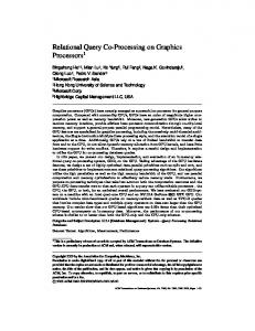
Figure 3. This figure summarises the overall flow of control in our FFT-based docking calculations, and it indicates the type of hardware which may be used for each step. For most steps, multiple CPU cores and multiple GPUs may be used simultaneously.
2.6. Implementing a Docking Server Because high performance GPUs are relatively expensive, we have developed HexServer, a web interface to Hex, in order to make our GPU-accelerated docking approach widely and freely available. The computational part of our server consists of a 32-node cluster running the CentOS operating system and using the “OAR” batch scheduling system (http://oar.imag.fr/). Each node consists of two quad-core Intel Xeon 2.5GHz CPUs, and eight of the nodes are equipped with two Nvidia Tesla C1060 GPUs. Hence a total of 256 CPU cores and 16 GPUs are available on our server. As shown in Figure 4, the web interface is implemented using the “PHP” scripting language, through which the user’s protein coordinate files are up-loaded and stored in a “MySQL” database along with the other parameters of the docking job. The PHP scripts perform some basic checks on the input data in order to highlight errors quickly and to avoid wasting processor time on the server. A shell script running on the compute server periodically polls the databases for new jobs. When a new job is found, another shell script is generated and is submitted to an OAR batch queue. Once a GPU node becomes available, this script executes the Hex job and copies the results files back to the MySQL database when the job has finished. Meanwhile, the PHP interface periodically polls the database for an indication that the job has completed, and it makes the results available as a job-specific web link.
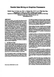
Figure 4. Schematic illustration of the HexServer architecture. The user interacts with the server via some simple PHP-based web pages, which store all input parameters and data in a MySQL database. The compute cluster periodically polls the database for new jobs, and it stores results back to the database for subsequent retrieval by the user via the web-interface.
inria-00537989, version 1 - 19 Nov 2010
3. Results 3.1. The “Hex” Docking Program The program “Hex” was developed to explore the use of the SPF approach for accelerating the first rigid body part of a protein docking calculation. Hex is an interactive program which lets a user load a pair of proteins, view them in a variety of 3D graphical modes, perform docking calculations, and visualise the results in a single easy-to-use environment. Hex runs equally on Linux, Windows, and Mac OS X systems, and it can use as many CPUs and GPUs as are available for docking calculations. Figure 5 shows a screen-shot of Hex on a Linux workstation. 3.2. The “HexServer” Web Server “HexServer” is an easy-to-use form-based interface through which users may upload a pair of protein structures in “PDB” format (http://www.pdb.org) to be docked by Hex. Figure 5 shows the web interface for defining the parameters of a docking job. If prior information about the possible binding site(s) is available, the user may specify an angular search range (e.g. 45°) for each protein with respect to the intermolecular axis in order to constrain the rotational search around the putative interface. For a blind unconstrained 6D docking run, it is normally sufficient to use the default values for all parameters. If the proteins to be docked have large and opposite formal charges, or if electrostatic interactions are known to be important, it is often beneficial to request a shape plus electrostatic calculation. Because HexServer aims to provide a relatively large number of putative complexes for re-scoring, the requested number of predictions is presented as a single compressed multi-structure PDB file. This file may be in any of the “zip,” “gzip,” or “bzip2” compression formats. The first 20 structures are also made available individually in uncompressed PDB format. Thus the user may quickly preview the predictions before down-loading the large multi-structure results file. 3.3. Overall Speed-Up Achieved For typical Hex docking calculations, we find that one C1060 GPU can evaluate around 170 million trial orientations per second. This corresponds to a speedup of at least a factor of 45 compared to a contemporary CPU core, which is up to two orders of magnitude faster than conventional Cartesian grid-based FFT docking approaches.
inria-00537989, version 1 - 19 Nov 2010
Figure 5. Left: a screen-shot of the Hex program. Centre and Right: screen-shots of the HexServer interface.
On our system, a typical exhaustive 6D rigid-body docking search takes around 15 seconds when using two C1060 GPUs simultaneously. Figure 6 summarises the overall performance improvements achieved by the GPU for several types of calculation. The times given include initialisation and file transfer times, hence the absolute speed-up is somewhat less than that mentioned above. Nonetheless, this figure shows that 1D FFT calculations benefit much more from using a GPU than the 3D FFT calculations. This is because the data for 1D FFTs is fed through the GPU multi-processors in a single pass, whereas 3D FFTs require multiple passes over the data, and this is relatively expensive on the GPU device architecture.
Figure 6. Comparison of total execution times for shape-only and shape plus electrostatic FFT calculations. Here, “CPU” refers to one core of a 3.2GHz i7-965 workstation, and “GPU” refers to a single FX-5800 GPU.
4. Discussion and Conclusion The CUDA toolkit has allowed the computationally intensive docking calculations in Hex to be ported relatively easily to high performance GPUs. Compared to using a single conventional CPU core, we achieve a computational speed-up of about a factor of 45 in the most favourable case. However, since multi-core CPUs are becoming increasingly common, it is perhaps fairer to compare one GPU with one quad-core CPU, which gives an improvement of about a factor of 10. Nonetheless, the absolute speed-up that GPUs give our protein docking application is considerable. Calculations which formerly took several hours may now be performed in an almost interactive time-scale. We believe that improving our ability to carry out and interact with computationally intensive simulations on remote servers, and directly on the desktop, will facilitate the study of complex macromolecular interactions. The Hex program may be downloaded from http://hex.loria.fr/. HexServer is available for public use at http://hexserver.loria.fr/.
Acknowledgements Part of this work was funded by BBSRC (grant ref. 1/B10454) and ANR (grant ref. ANR-08-CEXC-017-01). We thank Birama Ndiaye and Olivier Demengeon for assistance with the compute cluster, which is co-funded by INRIA and Region Lorraine.
References [1] [2]
inria-00537989, version 1 - 19 Nov 2010
[3] [4] [5] [6] [7] [8] [9] [10]
[11] [12] [13] [14] [15] [16]
[17] [18] [19] [20] [21]
E. M. Marcotte, P. Pellegrini, M. J. Thompson, T. O. Yeates, and D. Eisenberg. A combined algorithm for genome-wide prediction of protein function. Nature, 402:83–86, 1999. D. Eisenberg, E. M. Marcotte, I. Xenarios, and T. O. Yeates. Protein function in the post-genomic era. Nature, 405:823–826, 2000. R. B. Russell, F. Alber, P. Aloy, F. P. Davis, D. Korkin, M. Pichaud, M. Topf, and A. Sali. A structural perspective on protein-protein interactions. Current Opinion in Structural Biology, 14:313–324, 2004. P. Aloy, M. Pichaud, and R. B. Russell. Protein complexes: structure prediction challenges for the 21st century. Current Opinion in Structural Biology, 15:15–22, 2005. P. Aloy and R. B. Russell. Structural systems biology: modelling protein interactions. Nature Reviews Molecular Cell Biology, 7:188–197, 2006. S. J. Wodak and J. Janin. Computer analysis of protein-protein interaction. Journal of Molecular Biology, 124:323–342, 1978. D. W. Ritchie. Recent progress and future directions in protein-protein docking. Current Protein & Peptide Science, 9(1):1–15, 2008. C. J. Camacho, D. W. Gatchell, S. R. Kimura, and S. Vajda. Scoring docked conformations generated by rigid-body protein-protein docking. Proteins: Structure, Function and Genetics, 40:525–537, 2000. L. Li, R. Chen, and Z. Weng. RDOCK: refinement of rigid-body protein docking predictions. Proteins: Structure, Function and Genetics, 53:693–707, 2003. C. Zhang, S. Liu, and Y. Zhou. Docking prediction using biological information, ZDOCK sampling technique, and clustering guided by the DFIRE statistical energy function. Proteins: Structure, Function and Bioinfinformatics, 60:314–318, 2005. R. Chen, L. Li, and Z.Weng. ZDOCK: an initial-stage protein-docking algorithm. Proteins: Structure, Function and Bioinfinformatics, 52:80–87, 2003. S.R. Comeau, D.W. Gatchell, S. Vajda, and C.J. Camacho. ClusPro: a fully automated algorithm for protein-protein docking. Nucleic Acids Residues, 32:W96–99, 2004. D. Schneidman-Duhovny, Y Inbar, R Nussinov, and H.J. Wolfson. PatchDock and SymmDock: servers for rigid and symmetric docking. Nucleic Acids Residues, 33:W363–367, 2005. A Tovchigrechko and I.A. Vakser. GRAMM-X public web server for protein-protein docking. Nucleic Acids Residues, 34:W310–314, 2006. S Lyskov and J.J. Gray. The RosettaDock server for local protein-protein docking. Nucleic Acids Residues, 36:W233–238, 2008. E. Katchalski-Katzir, I. Shariv, M. Eisenstein, A. A. Friesem, and C. Aflalo. Molecular surface recognition: Determination of geometric fit between proteins and their ligands by correlation techniques. Proceedings of the National Academy of Science, 89:2195–2199, 1992. L. C. Biedenharn and J. C. Louck. Angular Momentum in Quantum Physics. Addison-Wesley, Reading, MA, 1981. A. Erdelyi, W. Magnus, F. Oberhettinger, and F. G. Tricomi. Higher Transcendental Functions Vol 2. McGraw-Hill, New York, 1953. D. W. Ritchie. High-order analytic translation matrix elements for real-space six dimensional polar Fourier correlations. J. Appl. Cryst., 38:808–818, 2005. D. W. Ritchie and G. J. L. Kemp. Protein docking using spherical polar Fourier correlations. Proteins: Structure, Function and Genetics, 39(2):178–194, 2000. D.W. Ritchie, D. Kozakov, and S. Vajda. Accelerating protein-protein docking correlations using a sixdimensional analytic FFT generating function. Bioinformatics, 24(4):810–823, 2008.


![[hal-00605714, v1] Secure extension of FPGA soft core processors ...](https://m.moam.info/img/260x300/hal-00605714-v1-secure-extension-of-fpga-soft-core_5a26f5551723dd9f7972dbb1.jpg)