Insight into Data Through Visualization Eduard Gr¨ oller Institute of Computer Graphics and Algorithms Vienna University of Technology A-1040 Vienna, Austria
[email protected] WWW home page: http://www.cg.tuwien.ac.at/home/
Abstract. Computer graphics, scientific visualization, information visualization, and graph drawing are areas which deal with visual information layout. They all use the remarkable properties of the human visual perception to rapidly absorb and analyse visual information. The paper discusses important visualization aspects and gives examples of how visualization techniques facilitate insight into data characteristics. The connection between visualization and graph drawing is shortly discussed.
1
Introduction
Computer graphics and visualization have come a long way in developing techniques and tools to support the human user in data analysis and investigation. As stated by R. Hamming: ”The purpose of computing is insight, not numbers”. The human visual system is well adapted to rapidly absorb and interpret large quantities of visual information. Scientific visualization deals with the representation, manipulation, and rendering of scientific data (measured, simulated or modelled data). Volume visualization and flow visualization are two important subbranches of scientific visualization. Several examples, e.g., medical visualization, shall illustrate how visual representations facilitate the understanding of underlying data characteristics. Scientific visualizations are often characterized by an inherent spatial context. This is not the case with information visualization. Information visualization on the other hand deals with interactive visualizations of abstract, often higher-dimensional, unstructured, and large data sets (e.g., data base content). Issues in information visualization are to select appropriate visual metaphors and to provide tools for efficient user interaction. With scientific visualization the user goal is often an analysis of the data, whereas with information visualization exploration and browsing through the abstract data is of major concern. Information visualization is also used to handle hierarchical or relational data. Such data is best represented in graph structures. These applications act as bridge between the visualization and graph drawing field. This paper shall help in intensifying collaborative contacts between these two areas. The primary goal is to show how visualization uses the considerable capabilities of the human visual perception for fast information acquisition and processing.
2
2
Computer Graphics
In general computer graphics [FvDFH96], [HB96] deals with computer supported methods and techniques to process images, animation sequences, and visual information. Computer graphics comprises generative computer graphics, image processing, and pattern recognition. Generative computer graphics takes an abstract, textual description to generate, manipulate, and render images. With image processing images are modified to facilitate further analysis by a human user or by a computer. Modifications include error elimination, contrast enhancement, detection of edges and homogeneous areas. Pattern recognition uses images to extract descriptive information which characterizes the content of the image. In the following we concentrate on generative computer graphics including interactivity. The three areas of computer graphics are, however, overlapping. Techniques of generative computer graphics are often used in displaying image-processing results. On the other hand rendering of computer-generated images may involve post-processing steps which thematically rather belong to image processing. The interactive input to graphical systems sometimes involves pattern-recognition algorithms. Certain subareas, e.g., color systems, equally belong to all three areas. Also most graphical devices are used in all three areas. Several important application fields of generative computer graphics include data visualization, presentation graphics, computer aided design (CAD), architecture, medical applications, geographic information systems (GIS), computer animation and movies, marketing, virtual reality, computer games, edutainment. 2.1
Human Visual Perception
Already in ancient times visual representations, e.g., rock paintings, petroglyphs, Egyptian tomb paintings, Minoan frescoes, expressed culture and traditions of primitive peoples and early civilizations. One reason for the popularity of pictorial presentations lies in the fact, that about 70% of all the information a person absorbs is acquired through the visual system. Human visual perception is a rather complicated multi-stage process. Important structures of the eye include the iris, lens, pupil, cornea, retina, vitreous humor, optic disk and optic nerve. The retina contains photoreceptors, i.e., rods and cones. Rods are the sensors on the retina which are responsible to detect greyscales and low levels of light. Cones are responsible for color perception and exist in three types. There are cones for detecting ”red”-, ”green”-, and ”blue”-light respectively. Therefore the human being is called a trichromat. There are about 20 times more rods than cones. Rods predominantly occur near the periphery of the retina whereas cones are concentrated near the center of the eye. Also the three types of color-sensitive cones occur in greatly varying numbers, i.e., there are many more ”green”-light sensitive cones than ”blue”-light sensitive ones. The retina further contains components which process the electrical information coming from the photoreceptors. Processing includes detection of intensities, edges, motion and color-signal transformations. The optic nerves from each eye transport the visual information to the brain, where it is combined and analysed in several stages. Combining the
3
two perspective views from the left and right eye respectively enables stereoscopic viewing. This facilitates the detection of spatial relations among viewed objects and distance estimations. Other effects that influence visual perception are: focus, accomodation, adaption, visual acuity, contrast sensitivity, simultaneous contrast, Mach-banding, color constancy, depth, shape, and texture detection. Human visual perception rapidly scans, recognizes and recalls images. It thus provides a high-bandwidth data-channel to the human brain. Visual perception, however, is a quite intricate process. Therefore it is essential to be aware of the major perceptual components in order to be able to produce expressive and effective visual representations. 2.2
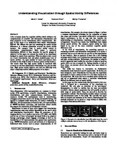
Computer-Graphics Workflow
Modelling
Rendering
Display
transformations input modeller
mapping clipping
image data output
visibility 3D data
shading
display devices
rasterization
Fig. 1. Computer-graphics workflow
Image generation in 3D computer graphics consists of a pipeline of consecutive steps (figure 1). The major stages in the computer-graphics workflow are modelling, rendering, and display. In the modelling stage the user specifies the scene data which shall be displayed. This includes object geometry, surface characteristics, lighting environment, motion and camera parameters. Objects are usually constructed through a modelling software which provides the resulting 3D data either as internal data structure or sequentially on file. The rendering stage performs the conversion of the 3D data into a 2D image in several steps. Transformations, e.g., translations, rotations, scalings, involve coordinate changes to modify position, size, and shape of objects. Mapping projects the 3D scene onto a 2D image plane. Usually perspective or parallel projection is used. With clipping parts of the scene which are outside the viewing frustum and
4
therefore invisible according to the current camera parameters are eliminated. In case of occluding objects a visibility algorithm determines the visible parts of the scene, i.e., objects closest to the view point. Shading takes surface characteristics and lighting conditions to determine the intensity or color of visible object regions. A small angle of light incidence (light source is directly above an object) produces bigger brightness values. As nowadays most display units are raster-oriented (e.g., screen displays) the geometry data, e.g., triangles, must be converted into raster data. This is done through raster-conversion algorithms. In the display stage the 2D data of the rendering step are either directly displayed or are stored in one of the many available image file formats. 2.3
Applications of Computer Graphics
Fig. 2. Architectural modelling [Tra95]
In the following we shortly and exemplarily discuss two of the many applications of computer graphics: computer-aided design (CAD) and computer graphics in education and training. Computer-aided design (CAD) deals with the use of computers to support and automatize construction and drawing processes. Computer graphics is a small but important part of CAD tasks. CAD is applied in the design of architectural models (figure 2), automobiles, aircrafts, computers, textiles (figure 3), and many other products. CAD programs typically offer the designer a multi-window environment, which depicts enlarged parts or different views of objects. Special rendering styles, e.g., wireframe rendering, allow an interactive and incremental construction process. CAD programs facilitate the efficient placement of generic shapes. Also connections between objects, annotations, and measurements are automatically included in design results. Variations or alternatives of a specific design are easily producible. A CAD model
5
Fig. 3. Textile modelling [GRS95]
also enables a computer simulation of important object characteristics like performance, stress or flow behavior. Simulation of realistic lighting conditions and surface rendering create a realistic image of the final product. In architectural applications CAD supports the design of floor plans, wiring, electrical outlets, complex lighting simulations, and walk-throughs (animations). CAD is a subarea of fields like CAE (computer-aided engineering) or CAP (computer-aided planing). Education and training has been an early driving force for computer graphics. Flight simulators are a typical example. They are special systems which provide persuasive visual feedback. The user is immersed in a training situation which is as realistic as possible. Other simulators are concerned with, e.g., airtraffic control, ships, heavy-equipment, car traffic. Models of physical systems or equipment allow to explore the functionality and behavior at reduced cost and risk. Understanding of processes is eased through computer-graphics views (e.g, cut-away views) which are not possible in reality. 2.4
Extending the Computer-Graphics Workflow
The traditional computer-graphics workflow (figure 1) is based on the desktop metaphor: data input and output is primarily done through keyboard, mouse and display screen. There are several possibilities to extend this traditional workflow. Virtual reality and augmented reality are two rather new areas, which fully or partially immerse a user into a computer generated virtual environment. These approaches use novel input and output techniques like (see-through) headmounted-displays, large projection units, 3D input devices. Figure 4 illustrates Studierstube [SFH+ 01], an augmented reality system where several users can collaboratively interact with virtual information. Essential components of virtual or augmented reality include immersion, real-time user interaction and feedback, and graphical (realistic) representation of the virtual world.
6
Typically the computer-graphics workflow simulates realistic image generation which means that elaborate lighting calculations (ray tracing, radiosity) are performed to emulate images of real-world scenes as closely as possible. Nonphotorealistic rendering on the other hand simulates different drawing styles: contour and silhouette rendering, pen and ink drawings, water color simulation, replication of brush strokes previously used by artists. Figure 5 shows a medical illustration [CMH+ 01] which uses non-photorealistic rendering. Perspective or parallel projection are first approximations of how the human eye perceives a 3D scene. With computer graphics more general (artistic) mapping strategies may be utilized. The 3D information may not only be mapped to a 2D image plane but onto a more general (curved) image surface. There may not be only one fixed view point but several view points within a single image. Again artists have already used such approaches. Figure 6 to the left shows a perspective rendering of a 3D object. In Figure 6 to the right the object is mapped by using an extended camera [LG96], i.e., the image surface is a bent cylinder, view points are changing from top to bottom of the image by moving along the cylinder axis.
Fig. 4. Studierstube augmented reality system [SFH+ 01]
3
Scientific Visualization
Scientific visualization [SM00] deals with the representation, manipulation, interaction, and rendering of scientific data. It allows to form a mental vision, image, or picture of something not visible or present to the sight, or of an abstraction. Visualization has been long used before the advent of the computer era. Typical examples include: geographic maps, nautical charts, weather charts,
7
Fig. 5. Non-photorealistic medical illustration [CMH+ 01]
Fig. 6. Perspective projection (left), extended camera (right) [LG96]
8
x-ray images, experimental flow visualization. The primary goal of visualization is to allow better insight into the data. Depending on the data to visualize and the visualization goal an appropriate technique must be selected among the large variety of available methods. The great diversity of inhomogeneous data sources include medical data, flow data, abstract data, geographic data, historical data (archeology), microscopic data (molecular physics), macroscopic data (astronomy). Data sources differ according to domain (continuous, discrete, grid), data range, dimensionality, data type (scalar, vector, tensor), structuring (sequential, relational, hierarchical, networked). Depending on the level of knowledge about the data scientific visualization tries to accomplish one of three high-level goals. If not much is known about the data, visualization offers exploration tools to support the user in finding hypotheses about the data. In case there are already hypotheses visualization is used to analyze the data with the goal of confirmation or refutation of these hypotheses. In case all relevant data characteristics are already known visualization is an efficient tool for communicating results, e.g., to non experts. Specific visualization goals are: identification (which data values are given in a certain area of the domain), localization (which parts of the domain do have a certain data value), correlation analysis, data comparison (spatial, temporal), distribution analysis (extrema, outliers, frequencies, clusters), categorization and classification. 3.1
Visualization Pipeline
data acquisition data is given data enhancement data is processed visualization mapping data is mapped to geometry rendering (3D®2D) data is transformed to images Fig. 7. Visualization pipeline
A visualization process encompasses several consecutive steps which are combined into the visualization pipeline (figure 7). Data acquisition produces data due to measurements (e.g., computed tomography in medicine), simulations (e.g.,
9
finite element methods for flow simulation), or modelling (e.g., differential equations to model a physical phenomenon). Data enhancement processes the raw data from the acquisition step. Data enhancement includes filtering (noise removal), resampling (to a different grid), data completion, calculating derived data (e.g., gradient information), data interpolation and reconstruction. Visualization mapping assigns visual properties to the data. This is the most crucial step in the visualization pipeline. Depending on the visualization mapping the same data might produce totally different images, and different parts of the data will be emphasized to a varying degree. This is also a crucial difference to photo-realistic computer graphics where real-world scenes are the target to approximate. In many cases with visualization there is no intuitive or obvious geometric representation of a specific data. Therefore only the desired investigation goal guides the selection of the most appropriate visual representation. As an example, medical data on a 3D grid (voxel data) can be visually represented by iso-surfaces. Another rather different representation would be to assign colors and opacities to each of the grid points. High dimensional objects can be represented through a great variety of geometric objects (icons, glyphs) whose properties (size, color, shape) encode the underlying information. Rendering is the last step in the visualization pipeline and uses computer- graphics techniques (projection, visibility, shading, compositing calculations) to produce images or animation sequences. Interactivity is very important in analyzing the data and can range from interactive manipulation of rendering parameters (e.g., camera modification) to changing visualization-mapping parameters (e.g., changing an iso-value). In the most general case, which usually is quite difficult to achieve, also the data acquisition process is interactively affected (computational steering). 3.2
Volume Visualization, Flow Visualization
Volume visualization and flow visualization are the major subbranches of scientific visualization. Volume visualization deals with displaying volume data, i.e., scalar data on a (regular) 3D grid. There are basically two types of visualization mappings for volume data. The first class of techniques derive iso-surfaces, e.g., skin and bone surface, which are rendered with traditional surface-based computer-graphics techniques. A typical representative is the marching-cubes algorithm. The second class of techniques do not produce any intermediate geometric structure but render the volume data directly. So-called transfer functions assign colors and opacities to individual voxels. These visual values are accumulated, e.g., along viewing rays, to produce semitransparent renderings of the volume data. With these techniques also the interior of volumetric structures are made visible. Typical representatives are volume ray casting, splatting, shear-warp-factorization, and Fourier volume rendering. Figure 8 shows the semitransparent volume-rendering of a CT head. Skin and blood vessels are depicted semi-transparently whereas the skull is rendered opaquely [KG01]. In figure 9 the CT data of a human colon is virtually stretched and unfolded. This allows a fast overview on the entire organ surface and facilitates polyp detection [BWKG01].
10
Flow visualization deals with flow data (vector data), typically 2D flow vec-
Fig. 8. Semi-transparent volume-rendering of CT head [KG01]
Fig. 9. Virtual colon unfolding for polyp detection [BWKG01]
tors on a 2D (grid) domain, or 3D flow vectors on a 3D (grid) domain. Often a numerical simulation is necessary to derive flow objects like streamlines, streaklines, path lines, and time lines. Either the local or the global flow behavior (laminar vs. turbulent flow) are of interest. Local behavior is visualized through glyphs whose geometric parameters (size, color) indicate local flow properties (velocity, vorticity, helicity,...). Glyps are also used to illustrate topological flow characteristics like fixed points, cycles, basins. Global behavior can be visualized through streamline placement or through anisotropic filtering of high-frequency textures (e.g., Line Integral Convolution). In this case the high-frequency texture is smeared along the flow. Figure 10 shows a tube represenation of a streamline in
11
a flow field. Additionally an important surface (called critical surface) is shown semi-transparently [WGP97]. Figure 11 illustrates a three-dimensional flow by a set of dashed streamlines. Streamline density behind a magic lens is increased to allow a more detailed inspection there [FG98].
Fig. 10. Flow visualization with streamline and critical surface [WGP97]
Fig. 11. Magic lens for 3D flow visualization [FG98]
4
Information Visualization
Information visualization is ”the use of computer-supported, interactive, visual representations of abstract data to amplify cognition” [CMS99]. As opposed to
12
scientific visualization information visualization deals with abstract often highdimensional data with mostly no inherent spatial structure. Major issues are to specify an appropriate easy to understand visual metaphor and to allow flexible user interaction. The primary goal of information visualization is the explorative investigation of large data bases. After gaining a broad overview of the data, zoom and filter operations are applied, and details are depicted on demand. Abstract data include linear data (tables, program source files, chronological lists), hierarchies (tree structures), networks (general graph structures, webs), attribute metadata (with type, size, age, in n-dimensional space), and information retrieval results (word co-occurency, similarity measures) [And01]. If the number of data elements to display is limited, then two or three dimensional graphical primitives are useful. A file system, for example, can be represented in 2D as a hyperbolic projection or in 3D as a hierarchical arrangement of cones (cone trees, cam trees). If the data base is very large focus-and-context approaches apply. The most interesting (and usually small) part of the data is represented in detail (focus). For orientation purposes the remaining, much larger part of the data is displayed as context information (concise representation on a higher level of abstraction). In the field of document visualization perspective wall and document lens realize such a focus-and-context approach, where the user can interactively determine the focus area. Often fisheye views and distorted views realize the focus-andcontext principle. In figure 12 another realization of focus-and-context is shown. SDOF (semantic depth of field) [KMH01] represents objects in the focus sharply and objects in the context blurry. In figure 12 to the left the white knight and those black chessmen threatening it are in focus. In figure 12 to the right the white knight and those white chessmen covering it are in focus. The blurry representation of the remainder allows a preattentive concentration on the objects in focus.
Fig. 12. SDOF: Semantic depth of field [KMH01]
13
Looking for dependencies in high-dimensional data with many attributes poses the problem of having to represent many dimensions simultaneously. With parallel coordinates individual dimensions are represented as vertical parallel lines. An n-dimensional data point is represented by connecting the individual coordinate components on these parallel lines. Figure 13 shows an extension of this concept: instead of parallel lines parallel planes are used. A six-dimensional curve is shown by projecting it into three planes. Corresponding projected points in adjacent planes are connected with each other [WLG97]. Another possibility
Fig. 13. Extended parallel coordinates
is the mapping of high-dimensional attributes to geometric properties of a two or three dimensional glyph. Individual data dimensions are encoded in length, size, and shape or in the arrangement of geometric objects. The appearance of the glyphs and their position facilitate the perception of dependencies and correlations. Graph drawing algorithms are also a good choice in depicting these interconnections. In general the typically very large and high-dimensional information spaces require efficient search strategies (browsing, dynamic queries, visual data mining). Often different views of the same data are linked together, i.e., manipulating data in one view simultaneously effects all the other views also.
5
Visualization and Graph Drawing
We have now discussed concepts of computer graphics, scientific visualization and information visualization. Comprising these areas broadly under the term visualization we now shortly discuss the connection to graph drawing. Figure 14 puts visualization and graph drawing into context and lists some topics where
14
both areas can profit from each other. Visualization predominantly deals with how to draw objects, whereas graph drawing is often concerned with layout problems, i.e., where to draw objects. Visualization deals with many different types of data and graph drawing is focussed on abstract graph data. Typically visualization handles (very) large data sizes (giga and tera bytes). Due to the high complexity of many layout algorithms graph drawing is concerned with relatively small data sizes. Visualization is an applied field in the sense that the performance of techniques is evaluated through user studies and runtime analyses. Graph drawing is more theoretical by studying theoretical complexity bounds. From the visualization side information visualization is the area closest to graph drawing. It is often dealing with networked data that can be represented as graphs, so graph drawing approaches are applicable. Visualization can
Visualization
Graph Drawing
· · · · ·
· · · · ·
how to draw objects heterogeneous data large data size applied nD data
where to draw objects abstrat graph data small data size theoretical mostly 2D data
· advanced visual represenations · interaction metaphors · layout for networked data, trees · fast, incremental drawing techniques Fig. 14. Comparison: visualization vs. graph drawing
provide graph drawing with advanced visual representations (shading, visibility, complex node and edge shapes, annotations). Information visualization has also come up with a set of interesting interaction metaphors which might also be useful for graph drawing applications. These are, e.g., focus-and-context, distortion techniques, hierarchical representations (e.g., level-of-detail with smooth transitions), interactive manipulation (insertion or deletion of edges and nodes). Graph drawing on the other hand has useful contributions for visualization whenever correlated and networked data must be displayed as graphs or trees. The layout expertise of the graph drawing community is not yet fully used in the visualization area. In visualization data sets are often incrementally increased or decreased (e.g., subset selection). Therefore it would also be very interesting to get incremental layout strategies from the graph drawing field. Graph drawers know where to put information, visualizers know how to put the information (vi-
15
sual representation). More interaction between these two groups will be fruitful to both areas.
References [And01] K. Andrews. Information visualisation. http://www2.iicm.edu/ivis, 2001. [BWKG01] A. Vilanova Bartroli, R. Wegenkittl, A. K¨ onig, and E. Gr¨ oller. Virtual colon unfolding. In IEEE Visualization 2001 Proceedings. IEEE Computer Society, October 2001. onig, and E. Gr¨ oller. Fast visualiza[CMH+ 01] B. Csebfalvi, L. Mroz, H. Hauser, A. K¨ tion of object contours by non-photorealistic volume rendering. Computer Graphics Forum, 20(3):C–452–C–460, September 2001. [CMS99] St. Card, J. Mackinlay, and B. Shneiderman. Readings in Information Visualization. Morgan Kaufmann, 1999. [FG98] A. Fuhrmann and E. Gr¨ oller. Real-time techniques for 3D flow visualization. In IEEE Visualization 1998 Proceedings, pages 305–312. IEEE Computer Society, October 1998. [FvDFH96] J. Foley, A. van Dam, S. Feiner, and J. Hughes. Computer Graphics: Principles and Practice, Second Edition in C. Addison-Wesley, Reading, MA, 1996. [GRS95] E. Gr¨ oller, R. T. Rau, and W. Strasser. Modeling and visualizatin of knitwear. IEEE Transactions on Visualization and Computer Graphics, 1(4):302–310, 1995. [HB96] D. Hearn and M. P. Baker. Computer Graphics, C Version. Prentice Hall, 1996. [KG01] A. K¨ onig and E. Gr¨ oller. Mastering transfer function specification by using VolumePro technology. In Spring Conference on Computer Graphics 2001, pages 279–286, April 2001. [KMH01] R. Kosara, S. Miksch, and H. Hauser. Semantic depth of field. In IEEE Symposium on Information Visualization Proceedings. IEEE Computer Society, October 2001. [LG96] H. L¨ offelmann and E. Gr¨ oller. Ray tracing with extended cameras. Journal of Visualization and Computer Animation, 7(4):211–228, October 1996. [SFH+ 01] D. Schmalstieg, A. Fuhrmann, G. Hesina, Zs. Szalavari, L. M. Encarnao, M. Gervautz, and W. Purgathofer. The Studierstube augmented reality project. In SIGGRAPH 2001 Course Notes (no. 27, Augmented Reality: The Interface is Everywhere). ACM Siggraph, 2001. [SM00] H. Schumann and W. M¨ uller. Visualisierung - Grundlagen und allgemeine Methoden. Springer, 2000. [Tra95] Ch. Traxler. Representation and realistic rendering of natural scenes with directed cyclic graphs. http://www.cg.tuwien.ac.at/research/rendering/csg-graphs/index.html, 1995. [WGP97] R. Wegenkittl, E. Gr¨ oller, and W. Purgathofer. Visualizing the dynamical behavior of wonderland. IEEE Computer Graphics & Applications, 17(6):71–79, December 1997. [WLG97] R. Wegenkittl, H. L¨ offelmann, and E. Gr¨ oller. Visualizing the behavior of higher dimensional dynamical systems. In IEEE Visualization ’97 Proceedings, pages 119–125. IEEE Computer Society, October 1997.