IEEE/ACM TRANS. AUDIO, SPEECH, AND LANGUAGE PROCESSING, VOL. XX, NO. YY, AUGUST 12, 2018
1
Insights Into Frequency-Invariant Beamforming with Concentric Circular Microphone Arrays Gongping Huang, Jingdong Chen, and Jacob Benesty
Abstract—This paper studies the problem of frequencyinvariant beamforming with concentric circular microphone arrays (CCMAs) and presents an approach to the design of frequency-invariant and symmetric beampatterns. We first apply the Jacobi-Anger expansion to each ring of the CCMA to approximate the beampattern. The beamformer is then designed by using all the expansions from different rings. In comparison with the existing work in the literature where a Jacobi-Anger expansion of the same order is applied to different rings, here in this contribution the order of the JacobiAnger expansion at a ring is related to its number of sensors and, as a result, the expansion order at different rings may be different. The developed approach is rather general. It is not only able to mitigate the deep nulls problem in the directivity factor (DF) and the white noise gain (WNG), that is common to circular microphone arrays (CMAs), and improve the steering flexibility, but is also flexible to use in practice where a smaller ring can have less microphones than a larger one. We discuss the conditions for the design of N th-order symmetric beampatterns and examples of frequency-invariant beampatterns with commonly used array geometries such as CMAs, CMAs with a sensor at the center, and CCMAs. We show the advantage of adding one microphone at the center of either a CMA or a CCMA, i.e., circumventing the deep nulls problem caused by the 0th-order Bessel function. Index Terms—Microphone arrays, circular microphone arrays, concentric circular microphone arrays, fixed and differential beamforming, frequency-invariant beampattern, white noise gain, directivity factor.
I. Introduction Microphone array beamforming is widely used to recover a speech signal of interest from noisy observations in voice communication and human-machine interfaces [1]–[10]. A considerable amount of attention has been paid to this area of research and many beamforming algorithms have been developed over the last three decades or so [11]– [18]. Generally, beamformers’ performance vary with the array geometry and its specifications. Among different geometries (such as linear, circular, planar, spherical, etc.) studied in the literature [19]–[21], circular microphone arrays (CMAs) have stood out in applications like teleconferencing, smart speakers, and soundboxes due to This work was supported in part the National Natural Science Foundation of China (NSFC) “Distinguished Young Scientists Fund” under Grant No. 61425005 and the NSFC-ISF (Israel Science Foundation) joint research program under Grant No. 61761146001. G. Huang and J. Chen are with the Center of Intelligent Acoustics and Immersive Communications, Northwestern Polytechnical University, 127 Youyi West Road, Xi’an, Shaanxi 710072, China (e-mail:
[email protected],
[email protected]). J. Benesty is with INRS-EMT, University of Quebec, 800 de la Gauchetiere Ouest, Montreal, QC H5A 1K6, Canada (e-mail:
[email protected]).
their flexibility in beam steering as compared to linear microphone arrays (LMAs) [22]–[26], and compactness as compared to spherical microphone arrays (SMAs) [27]– [32]. Consequently, beamforming with CMAs has been a hot topic in microphone array processing over the last decade or two. While different beamformers with CMAs have been investigated, the differential beamformer is now dominantly used in practical systems because it can form frequency-invariant beampatterns and has the potential to attain high directional gains [32]–[35]. A comprehensive coverage of the design of differential beamformers with uniform CMAs (UCMAs) can be found in [33]. In general, with a UCMA, one can design an N thorder differential microphone array (DMA) beampattern with 2N sensors. However, the resulting beamformer would suffer from a number of issues. 1) White noise amplification, i.e., the white noise gain (WNG) is negative (in dB) at low frequencies and, as a result, any array imperfection such as sensor self noise and mismatch among different sensors will be amplified. 2) Limited steering ability, i.e., the differential beamformer is guaranteed to perfectly steer (i.e., without affecting its beampattern) only to M different directions, i.e., the M angular positions where the array elements are located. 3) Irregularity of the beampatterns and the directivity factor (DF) at some frequencies, i.e., the beamformer coefficients are a function of the Bessel functions, which in turn depend on the array specifications and frequency. If at some frequency the Bessel function approaches to 0, the absolute value of the corresponding beamformer coefficients becomes very large, leading to irregular beampatterns and deep nulls in the DF. An efficient way to deal with the problem of white noise amplification is to use of the so-called minimum-norm method, which maximizes the WNG by using more than 2N microphones to design an N thorder DMA beampattern. However, this approach may deteriorate the DF and more nulls would appear in the frequency range of interest [37]. Recently, an approach was developed to design robust steerable differential beamformers with UCMAs based on the Jacobi-Anger expansion [36], which is an optimal approximation of the beampattern from a least-squares error (LSE) perspective [39]. The resulting beamformer exhibits full steering ability, i.e., the beampattern can be perfectly steered to any look direction in the plane where the sensors are located; but it still suffers from the problem of the DF irregularity, as the minimum-norm approach in [33]. One possible method to deal with this problem is by using rigid baffled circular arrays, where the microphones
IEEE/ACM TRANS. AUDIO, SPEECH, AND LANGUAGE PROCESSING, VOL. XX, NO. YY, AUGUST 12, 2018
are mounted on a rigid, infinite cylinder (or sphere). The incident sound wave is scattered by the cylinder [40]– [42], and the pressure is then the superposition of the incident pressure and scattered pressure [43]–[45]. While it can mitigate the mentioned problem, using rigid baffled arrays is not very practical in real applications due to the complexity of the array structure and difficulty of mounting sensors as well as controlling the beampattern. A more practical and efficient method in dealing with both the problems of white noise amplification and the DF irregularity is by using concentric CMAs (CCMAs). In [37], we presented a method to design robust differential beamformers with uniform CCMAs (UCCMAs). For a same order differential beamformer, a UCCMA can offer much better performance than a UCMA in terms of WNG and DF consistency over different frequencies. Furthermore, the beampattern with the method in [37] is fully steerable, meaning that its breampattern can be steered to any direction in the plane where the sensors are located. However, this method also suffers from two limitations. 1) To design an N th-order desired DMA beampattern, each ring needs to have at least 2N + 1 microphones to support the N th-order Jacobi-Anger expansion. This would lead to difficulties in designing small, compact UCCMAs where the inner rings are small in size and it is difficult to mount many microphones. 2) The microphones in different rings need to be aligned, which reduces the design flexibility. More recently, we extended the work in [37] to the case where the microphones in different rings do not have to be aligned [38]. But the algorithm in [38] still assumes that different rings have the same number of sensors. In this paper, we reexamine the differential beamforming problem with CCMAs and present a general design method. In comparison to the work in [37], [38], the major contributions of this paper are as follows. 1) We develop a general approach to the design of robust CCMA differential beamformers with fully steerable and frequency-invariant beampatterns. In this approach, the beamformer’s beampattern corresponding to different rings is approximated with the Jacobi-Anger expansion of a different order, depending on the number of sensors. We show that one can obtain an N th-order desired and symmetric beampattern as long as one ring has 2N + 1 or more sensors, which is a generalization of the work in [37], [38]. With this method, the array structure can be very flexible since the inner rings can have less microphones than the outer ones and the microphones in different rings do not need to be aligned. 2) We discuss in great detail the design of frequency-invariant beampatterns with four commonly used array structures, i.e., CMAs, CMAs with one microphone at the center, CCMAs with two rings, and CCMAs with two rings and a microphone at the center. 3) We discuss and prove the advantages and limitations of adding a microphone at the center of either a CMA or CCMA, i.e., it can significantly improve the DF irregularity problem by dealing with the zeros caused by the 0th-order Bessel functions. The remainder of this paper is organized as follows. Sec-
2
m
ψ1,m
2 m
.
2 ψP,m
θ 2
1
1
1
MP
M1
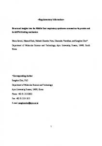
Fig. 1. Illustration of a CCMA with P rings, where ψp,m is the angular position of the mth array sensor on the pth ring and θ is the source incidence angle.
tion II presents the signal model, problem formulation, and performance measures. Section III describes frequencyinvariant beampatterns associated with differential beamforming. Section IV presents a design algorithm that can form any desired frequency-invariant beampattern. We then show in Section V how to apply the design method to four commonly used circular array structures and compare their pros and cons. Section VI presents some analysis and simulation results for comparison and validation. Finally, some conclusions are given in Section VII. II. Signal Model, Problem Formulation, and Performance Measures We consider a CCMA composed of P rings, placed on a polar plane, where the pth (p = 1, 2, . . . , P ) ring, with a radius of rp , consists of Mp omnidirectional microphones, as illustrated in Fig 1. Without loss of generality, we assume that the center of the CCMA coincides with the pole of the two-dimensional polar coordinate system and azimuthal angles are measured anti-clockwise from the polar axis. If a UCCMA as in [37] is used, the angular position of the mth array element on the pth ring is ψp,m =
2π(m − 1) , Mp
(1)
where p = 1, 2, . . . , P , m = 1, 2, . . . , Mp . In this study, however, we consider a more general case without restricting the first sensor at the pth ring to be on the polar axis. In this scenario, the angular position of the mth array element on the pth ring can be written as ψp,m = ψp,1 +
2π(m − 1) , Mp
(2)
with ψp,1 ≥ 0 being the angular position of the first microphone on the pth ring. Apparently, (1) is a particular case of (2) with ψp,1 = 0. It is seen from (2) that the proposed signal model does not need microphones in different rings to be aligned when all rings have the same number of sensors. This is useful in real applications,
IEEE/ACM TRANS. AUDIO, SPEECH, AND LANGUAGE PROCESSING, VOL. XX, NO. YY, AUGUST 12, 2018
especially when using a CCMA with a small and compact aperture. It should be noticed that the conventional methods developed to design frequency-invariant beampatterns with CCMAs based on the model in (1) require the microphones in different rings to be aligned when M1 = M2 = · · · = MP and therefore cannot be applied to the model in (2). With the model given in (2), the coordinates of the mth microphone at the pth ring are written as T
(3)
rp,m = rp [cos ψp,m sin ψp,m ] ,
where the superscript T is the transpose operator. We consider a plane wave, that propagates in an anechoic acoustic environment at the speed of sound, i.e., c = 340 m/s, and impinges on the CCMA. The direction of the source signal to the array is parameterized by the azimuth angle θ. In this ∑Pscenario, the steering vector of length M , where M = p=1 Mp is the total number of microphones, is defined as [37], [46] [ ]T d (ω, θ) = dT1 (ω, θ) dT2 (ω, θ) · · · dTP (ω, θ) , (4) where
[ dp (ω, θ) = eȷϖp cos (θ − ψp,1 ) eȷϖp cos (θ − ψp,2 ) ( ) ]T (5) · · · eȷϖp cos θ − ψp,Mp
is the pth ring’s steering vector, ȷ is the imaginary unit with ȷ2 = −1, and ϖp = ωrp /c, with ω = 2πf being the angular frequency and f > 0 being the temporal frequency. Generally, it is necessary to assume that the interelement spacing is less than half the acoustic wavelength to avoid spatial aliasing. In this paper, we consider small values of the interelement spacing such that the array works as a DMA, so we assume that this condition easily holds [1], [47]. In all voice and speech related applications, the signal of interest that is picked up by microphones is generally contaminated by noise, interference, and reverberation. Beamforming aims at recovering the signal of interest from noisy observations. Consider a general case where the desired signal comes from the direction θs and the corresponding propagation vector is d (ω, θs ). The objective of this paper is to design a beamforming filter with a desired, frequency-invariant beampattern whose main beam points in the direction θs (look direction). To do ∗ that, a complex weight, Hp,m (ω), is applied at the output of the mth sensor on the pth ring, where the superscript ∗ denotes complex conjugation. The weighted outputs are then summed together to form the beamformer’s output. Putting all the weights together in a vector of length M , we get [ ]T , (6) h (ω) = hT1 (ω) hT2 (ω) · · · hTP (ω) where hp (ω) =
[
Hp,1 (ω) Hp,2 (ω) · · ·
Hp,Mp (ω)
]T
is the spatial filter of length Mp for the pth ring.
(7)
3
In our context, the distortionless constraint in the look direction is needed, i.e., hH (ω) d (ω, θs ) = 1,
(8)
where the superscript H is the conjugate-transpose operator. Now that all variables are clearly defined, we give some useful performance metrics, i.e., the beampattern, the directivity factor (DF), the directivity index (DI), and the white noise gain (WNG), to evaluate the performance of the beamforming algorithms. The beampattern describes the sensitivity of the beamformer to a plane wave impinging on the CCMA from the direction θ. It is given by [47] B [h (ω) , θ] = hH (ω) d (ω, θ) =
Mp P ∑ ∑
(9)
∗ Hp,m (ω) eȷϖp cos (θ − ψp,m ) .
p=1 m=1
The DF quantifies the ability of the beamformer in suppressing spatial noise from directions other than the look direction. It can be written as [1] 2 H h (ω) d (ω, θs ) , (10) D [h (ω)] = H h (ω) Γd (ω) h (ω) where the elements of Γd (ω) are ( ) ωδij [Γd (ω)]ij = sinc , c
(11)
with δij = ∥ri − rj ∥2 being the distance between microphone i and j, ∥ · ∥2 being the Euclidean norm, and ri , rj ∈ {r1,1 , r1,2 , . . . , rp,Mp , . . . , rP,MP } are coordinates of the microphones. It is clear that D [h (ω)] ≤ dH (ω, θs ) Γ−1 d (ω) d (ω, θs ) , ∀h (ω). The DI is simply the DF expressed in decibels [1], i.e., DI [h (ω)] = 10 log10 D [h (ω)] .
(12)
The WNG evaluates the sensitivity of a beamformer to some array imperfections, e.g., sensor self noise, mismatch among different sensors, etc. It is defined as [1] 2 H h (ω) d (ω, θs ) W [h (ω)] = . (13) hH (ω) h (ω) It can be verified that W [h (ω)] ≤ M , ∀h (ω). III. Desired Frequency-Invariant Beampattern To acquire high fidelity speech and audio signals, it is important that the beamformers have frequency-invariant beampatterns. Otherwise, distortion may be added into the signal of interest after beamforming. In this work, we consider to design fixed beamformers with frequencyinvariant, symmetric beampatterns as with DMAs. The
IEEE/ACM TRANS. AUDIO, SPEECH, AND LANGUAGE PROCESSING, VOL. XX, NO. YY, AUGUST 12, 2018
frequency-invariant symmetric beampattern of an N thorder DMA with the main beam pointing in the direction 0 is given by [47] B (aN , θ) = =
N ∑
aN,n cos (nθ) n=0 aTN pc (θ) ,
(14)
where aN,n , n = 0, 1, . . . , N , are real coefficients, and [ ]T , aN = aN,0 aN,1 · · · aN,N [ ]T pc (θ) = 1 cos θ · · · cos (N θ) . The values of the coefficients aN,n , n = 0, 1, . . . , N , determine the shape of the beampattern. In the direction of the main beam, i.e., θ = 0, the beampattern should be equal to 1, i.e., B (aN , 0) = 1. Therefore, we have N ∑
(15)
aN,n = 1.
n=0
In real applications, the steering capability is an important issue, so in this work, we write the beampattern corresponding to a steering angle θs as [36] B (b2N , θ − θs ) =
N ∑
b2N,n eȷn(θ−θs )
(16)
n=−N T
= [Υ (θs ) b2N ] pe (θ) = cT2N (θs ) pe (θ) = B [c2N (θs ) , θ] , where
{
b2N,0 = aN,0 b2N,i = b2N,−i =
1 aN,i , i = 1, 2, . . . , N 2
and
( ) Υ (θs ) = diag eȷN θs , . . . , 1, . . . , e−ȷN θs , [ ]T b2N = b2N,−N · · · b2N,0 · · · b2N,N , [ −ȷN θ ] ȷN θ T ··· 1 ··· e pe (θ) = e ,
βn (ϖp ) = ȷn Jn (ϖp )
(18)
is the circular harmonic coefficient and Jn (ϖp ) is the nthorder Bessel function of the first kind with J−n (ϖp ) = (−1)n Jn (ϖp ). Equation (18) assumes a free field, which may suffer from significant degradation at some frequencies where those Bessel functions approach zero. One way to circumvent this problem is by using a rigid baffled circular array (the sensors are mounted on a rigid, infinite cylinder or sphere) [40], [41], where the sound wave is scattered by the cylinder and the pressure is the superposition of the incident pressure and scattered pressure. In this case, the circular harmonic coefficient βn (ϖp ) in (18) is replaced by [40], [41], [48] Jn′ (ϵϖp ) Hn(1) (ϖp ) , β¯n (ϖp ) = Jn (ϖp ) − ′(1) Hn (ϵϖp )
(19)
(1)
where Hn (ϖp ) is the nth-order Hankel function of the first kind, the superscript ′ denotes the derivative operation, and ϵ = rc /r, with rc being the radius of the cylinder. This method has been shown to be able to circumvent the nulls problem at high frequencies to some extent as has been discussed in the literature with UCAs. However, the rigid baffled circular array is not often used in practice due to the complexity of designing such a structure and difficulty to control the beampattern. So, in this study we stick with βn (ϖp ) defined in (18). To design an N th-order symmetric beampattern, it is generally a standard practice to limit the Jacobi-Anger expansion in (17) to the order N [37]. We therefore have N ∑
βn (ϖp ) eȷn(θ−ψp,m ) .
(20)
n=−N
T
· · · c2N,0 (θs ) · · · c2N,N (θs )] .
Clearly, the main beam of (16) is in the direction θs and B (b2N , θ − θs ) is symmetric with respect to the line θs ↔ θs + π where θ ∈ [θs , θs + π]. It can be checked from (16) that a rotation of the beampattern corresponds to a simple modification of its coefficients. IV. Beamformer and Beampattern Design It has been shown that the optimal approximation of the beamformer’s beampattern with a CMA from a least-squares error (LSE) perspective is the Jacobi-Anger expansion [39]. Following the same principle, the JacobiAnger expansion is applied to the exponential in (9) [36], [37]: ∞ ∑ eȷϖp cos (θ − ψp,m ) = βn (ϖp ) eȷn(θ−ψp,m ) , (17) n=−∞
where
eȷϖp cos (θ − ψp,m ) ≈
c2N (θs ) = Υ (θs ) b2N = [c2N,−N (θs )
4
With this approximation, it was shown in [37] that an N th-order beampattern can be designed if there are at least 2N + 1 microphones in each ring. However, this method requires different rings to have the same number of sensors, which makes it difficult to use in small, compact CCMAs, where the inner rings are small in size and it is difficult to mount many microphones. In practice, it makes more sense to mount more microphones in a larger ring than in a smaller one. Considering this, we attempt in this work to extend the method in [37] to a more general case with more flexibility on the design of frequency-invariant beampatterns with CCMAs. We propose to approximate the exponential function in the beamformer’s beampattern in each ring according to its number of microphones. We generally assume that an inner ring has less sensors than an outer ring, though the method developed here can be applied to the case where each ring has any number of sensors. Specifically, we approximate the exponential function in the beamformer’s beampattern corresponding
IEEE/ACM TRANS. AUDIO, SPEECH, AND LANGUAGE PROCESSING, VOL. XX, NO. YY, AUGUST 12, 2018
to the pth ring with an order of Np (Np ≤ N ), i.e., eȷϖp cos (θ − ψp,m ) ≈
Np ∑
βn (ϖp ) eȷn(θ−ψp,m ) .
(21)
From (27), one can find the relation between the beampattern of a CCMA and the N th-order desired symmetric beampattern, i.e.,
n=−Np
ȷn
In this case, we only need to ensure that the pth ring has no less than 2Np + 1 microphones. Certainly, to design an N th-order symmetric beampattern, we need to ensure that at least one ring can support the N th-order Jacobi-Anger expansion, i.e., we should have max{Np , p = 1, 2, . . . , NP } = N.
(22)
In real applications, it is obviously preferable that more microphones are mounted on an outer ring of the CCMA. For the convenience of analysis, we approximate the exponentials in the beamformer’s beampattern in outer rings with higher orders, and inner rings with lower orders, i.e., N1 ≥ N2 ≥ · · · ≥ NP . Substituting (21) into the beampattern of a CCMA given in (9), we obtain the approximative pattern:
Mp P ∑ ∑ p=1 m=1
=
P ∑
Np ∑
∗ Hp,m (ω)
∑
βn (ϖp ) eȷn(θ−ψp,m )
n=−Np
Np
eȷnθ βn (ϖp )
p=1 n=−Np
Mp ∑
(23) In order to relate (23) to the desired beampattern in (16), we can, alternatively, write (21) as eȷϖp cos (θ − ψp,m ) ≈
βn′ (ϖp ) eȷn(θ−ψp,m ) ,
(24)
n=−N
where βn′ (ϖp ) = αp,n βn (ϖp )
(25)
is the modified circular harmonic coefficient, with { 1, n = ±1, ±2, . . . , ±Np αp,n = 0, n = ±(Np + 1), ±(Np + 2), . . . , ±N
(26)
being a binary coefficient. Now, substituting (24) into (23) gives
eȷnθ βn′ (ϖp )
p=1 n=−N
=
eȷnθ ȷn
n=−N
∑
Mp ∑
ψ n,p =
[
e−ȷnψp,1
e−ȷnψp,2
···
e−ȷnψp,Mp
m=1 P ∑
αp,n Jn (ϖp )
p=1
Mp ∑
n=−Np
eȷnθ c2N,n (θs ) .
]T
(28)
(29)
is a vector of length Mp . It is more convenient to write (28) as ȷn ψ Tn (ω) h∗ (ω) = c2N,n (θs ) ,
n = ±1, ±2, . . . , ±N, (30)
where
[ ψ n (ω) = α1,n Jn (ϖ1 ) ψ Tn,1 α2,n Jn (ϖ2 ) ψ Tn,2 ]T · · · αP,n Jn (ϖP ) ψ Tn,P
(31)
Ψ (ω) h (ω) = J∗ Υ∗ (θs ) b2N , where
[
1
1 J = diag −N , . . . , 1, . . . , N ȷ ȷ
(32) ]
is a (2N + 1) × (2N + 1) diagonal matrix and H ψ −N (ω) .. . H Ψ (ω) = ψ 0 (ω) .. . H ψ N (ω)
(33)
(34)
is a (2N + 1) × M matrix, which has full-column rank. The minimum-norm solution of (32) leads to [ ]−1 hMN (ω) = ΨH (ω) Ψ (ω) ΨH (ω) J∗ Υ∗ (θs ) b2N . (35)
(36)
With (35), we can design a given desired symmetric beampattern with a CCMA. For ease of exposition, we call (35) the frequency-invariant beamformer with CCMA (FIB-CCMA).
∗ e−ȷnψp,m Hp,m (ω)
∗ (ω) e−ȷnψp,m Hp,m
V. Performance Analysis and Some Special Cases
m=1
Np
=
where
h (ω) = Ψ−1 (ω) J∗ Υ∗ (θs ) b2N .
P N ∑ ∑
N ∑
n = ±1, ±2, . . . , ±N,
When M = 2N + 1, the solution becomes
BN [h (ω) , θ] =
αp,n Jn (ϖp ) ψ Tn,p h∗p (ω) = c2N,n (θs ) ,
p=1
∗ e−ȷnψp,m Hp,m (ω) .
m=1
N ∑
P ∑
is a vector of length M . It is clearly seen from (30) that the beamforming filter, h (ω), can be obtained by solving a linear system of equations constructed from the optimal approximation, i.e.,
BN [h (ω) , θ] =
5
(27)
In this section, we first discuss the performance of the FIB-CCMA and then show some design examples with commonly used structures of CCMAs.
IEEE/ACM TRANS. AUDIO, SPEECH, AND LANGUAGE PROCESSING, VOL. XX, NO. YY, AUGUST 12, 2018
A. Performance Analysis The elements of the matrix Ψ (ω) ΨH (ω) are H ψ i (ω) ψ j (ω) , i, j = 0, ±1, ±2, . . . , ±N . It is clear that ψH (ω) ψ i (ω) = i
P ∑
2 αp,n Ji2 (ϖp ) ψ H i ψi
p=1
=
P ∑
Mp αp,n Ji2 (ϖp ) ,
p=1 2 where we have used the fact that αp,n = αp,n and ψ H i ψi = Mp , and for i ̸= j,
ψH (ω) ψ j (ω) i =
P ∑
αp,i αp,j Ji (ϖp ) Jj (ϖp ) ψ H i ψj
p=1
=
P ∑
αp,i αp,j Ji (ϖp ) Jj (ϖp )
p=1
=
P ∑
M ∑
eȷ(i−j)ψm
m=1
αp,i αp,j Ji (ϖp ) Jj (ϖp )
p=1
M ∑
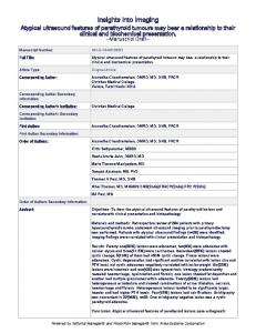
Figure 2 plots the squared Bessel functions of order 0 to order 4 as a function of ϖ. As seen, six nulls appear in the studied frequency range, where the first and fourth nulls are from the 0th-order Bessel function, the second and sixth nulls are from the 1st-order Bessel function, the third null is from the 2nd-order Bessel function, and the fifth null is from the 3rd-order Bessel function. Clearly, the lower the order of the Bessel functions, the more the nulls. So, it is safe to say that the nulls problem in beamforming with CMAs are mainly caused by loworder Bessel functions. In real applications with CMAs, it is important to know how many nulls should be dealt with, which is influenced by the radius of the array and the frequency range of interest. For example, with a frequency range of interest from 0 Hz to 8 kHz and a CMA with a radius of 3 cm, the maximum ϖ is approximately 4.4 and there are two nulls introduced by the 0th- and 1st-order Bessel functions. In this case, we only need to improve the performance degradation caused by the 0th- and 1st-order Bessel functions.
eȷ2π(i−j)(m−1)/M
m=1
= 0. As a consequence, we can express Ψ (ω) ΨH (ω) as in (36). Substituting the definitions of Ψ (ω), J, c2N (θs ), and (36) into (35), one can deduce the beamforming coefficient corresponding to the mth array element on the pth ring, i.e., Hp,m (ω) =
6
N ∑ ȷn αp,n b2N,n Jn (ϖp ) eȷnψp,m eȷnθs , (37) ∑P 2 i=1 Mi αi,n Jn (ϖi ) n=−N
which is a function of the Bessel functions from order ±N . The denominator in (38), i.e., ∑P 0 to order 2 (ϖ M α J i ), consists of squared Bessel functions. i i,n n i=1 For P = 1 (i.e., only one ring is used) and when the value of the Bessel function approaches to zero, the filter coefficient may become enormously large, which leads to either an unstable or an ill-conditioned beamformer. This problem, however, generally becomes less serious for P > 1 because the zeros of the Bessel functions with different radii appear at different positions (frequencies). This shows the advantage of a CCMA over a CMA, where the performance degradation caused by the zeros of the Bessel functions can be improved by using multiple rings. It is also seen from (37) that steering of the proposed beamformer corresponds to a simple multiplication of its coefficients by eȷnθs . ∑P
Ψ (ω) ΨH (ω) =
p=1
2 Mp αp,−N J−N (ϖp )
B. CCMAs with Two Rings We first consider a special case of the CCMA with two rings, where the first ring, with a radius of r1 , consists of M1 omnidirectional microphones, and the second ring, with a radius of r2 , consists of M2 omnidirectional microphones. Without loss of generality, we assume that r1 > r2 , M1 ≥ M2 , and the exponential functions in the beamformer’s beampattern corresponding to the first and second rings are approximated by the JacobiAnger expansions of order N1 and N2 (N = N1 ≥ N2 ), respectively. Then, according to (37), we have
Hp,m (ω) =
N ∑ n=−N
ȷn αp,n b2N,n Jn (ϖp ) eȷnψp,m eȷnθs . M1 α1,n Jn2 (ϖ1 ) + M2 α2,n Jn2 (ϖ2 ) (38)
Clearly, the combination of different Bessel functions in the denominator of (38) can avoid the nulls problem. To see the role of each ring in the performance of the beamformer more clearly, we rewrite the beamforming coefficients corresponding to different microphone rings. The beamforming coefficients for the microphones at the
..
.
∑P p=1
.
Mp αp,0 J02 (ϖp ) ..
.
∑P p=1
2 Mp αp,N JN (ϖp )
(36)
IEEE/ACM TRANS. AUDIO, SPEECH, AND LANGUAGE PROCESSING, VOL. XX, NO. YY, AUGUST 12, 2018
7
the microphones at the first ring as
10 0
H1,m (ω) =
-10
b2N,0 J0 (ϖ1 ) (0) + M1 J02 (ϖ1 ) N ∑ ȷn b2N,n eȷnψ1,m eȷnθs + . M1 Jn (ϖ1 )
J02
-20 -30
(41)
n=−N n̸=0
-40 -50
Clearly, the denominator in the filter coefficients corresponding to the 0th-order Bessel function is J02 (0) + M1 J02 (ϖ1 ), which does not have zeros; but the filter coefficients corresponding to the other orders is Jn2 (ϖ2 ), which still suffers from nulls problem. The beamforming coefficient for the microphone at the center is
-60 -70 -80 0
1
2
3
4
5
6
7
Fig. 2. The value of Jn2 (ϖ) as a function of ϖ for different values of n. Conditions: M = 8 and r = 1.5 cm.
first ring are N2 ∑ ȷn b2N,n Jn (ϖ1 ) eȷnψ1,m eȷnθs H1,m (ω) = M1 Jn2 (ϖ1 ) + M2 Jn2 (ϖ2 ) n=−N2
+
∑
n=±(N2 +1),...,±N
ȷn b2N,n eȷnψ1,m eȷnθs , M1 Jn (ϖ1 )
(39)
H2,1 (ω) =
J02
b2N,0 J0 (0) . (0) + M1 J02 (ϖ1 )
(42)
It is clearly seen that the denominator of this coefficient is a sum of two different Bessel functions, i.e., J02 (ϖ1 ) and J02 (ϖ2 ), and this sum does not have zeros. Consequently, adding a single microphone at the center of the ring can but only improve the performance degradation caused by the zeros of the 0th-order Bessel functions. In other words, CCMAs with one ring and a center microphone can mitigate the nulls problem in the frequency band of interest, but only to a certain extent.
and for the microphones at the second ring are H2,m (ω) =
N2 ∑ ȷn b2N,n Jn (ϖ2 ) eȷnψ2,m eȷnθs . M1 Jn2 (ϖ1 ) + M2 Jn2 (ϖ2 )
D. CMAs (40)
n=−N2
From (39) and (40), we see that, from order 0 to order ±N2 , the denominators in the filter coefficients are a combination of two different Bessel functions, i.e., M1 Jn2 (ϖ1 ) + M2 Jn2 (ϖ2 ). Since ϖ1 ̸= ϖ2 , the FIB-CCMA with two rings can improve the performance degradation caused by the zeros of the Bessel functions of orders 0, ±1, . . . , ±N2 . From the orders from ±(N2 + 1) to ±N , the denominators in the filter coefficients consist of only one Bessel function, i.e., Jn2 (ϖ1 ). In this case, the performance degradation caused by ±(N2 + 1), . . . , ±N order Bessel functions cannot be improved. This is practically very interesting since the nulls problem are more likely to be caused by low-order Bessel functions, and the nulls problem caused by higher-order Bessel functions are generally out of the frequency band of interest and do not need to be worried about.
C. CCMAs with One Ring and a Center Microphone Another special case of CCMAs is by adding a single microphone at the center of a CMA, which can be viewed as a CCMA with two rings where the first ring with a radius of r1 consists of M1 omnidirectional microphones and the second ring with a radius of 0, consists of a single omnidirectional microphone. Using the fact that ϖ2 = 0, ψ2,m = 0, we can write the beamforming coefficients for
For comparison, we also show the special case of CCMAs with a single ring, i.e., CMAs. The resulting beamformer’s coefficients are N ∑ ȷn b2N,n eȷnψm eȷnθs Hm (ω) = . M Jn (ϖ)
(43)
n=−N
As in (41), we rewrite (43) in an alternate form as Hm (ω) =
N ∑ ȷn b2N,n eȷnψm eȷnθs b2N,0 + . M Jn (ϖ) M J0 (ϖ)
(44)
n=−N n̸=0
Comparing (44) with (41), we see the difference is the 0th-order component in the beamforming coefficients. In (44), the denominator is the 0th-order Bessel function, M J0 (ϖ). If J0 (ϖ) approaches zero, the beamformer would suffer from significant degradation in performance. In comparison, the denominator of the beamforming coefficients in (41) is a combination of two squared 0thorder Bessel functions. Since the combined result generally does not have zeros, there is no longer performance degradation by the nulls of the 0th-order Bessel function. This corroborates the advantage of adding a single microphone at the center of a CMA. E. CCMAs with Two Rings and a Center Microphone The last special case of CCMAs considered in this work is with two rings and a center microphone. In this case,
IEEE/ACM TRANS. AUDIO, SPEECH, AND LANGUAGE PROCESSING, VOL. XX, NO. YY, AUGUST 12, 2018
the beamforming coefficients for the microphones at the first ring are b2N,0 J0 (ϖp ) J02 (0) + M2 J02 (ϖ2 ) + M1 J02 (ϖ1 ) N2 ∑ ȷn b2N,n Jn (ϖ1 ) eȷnψ1,m eȷnθs
H1,m (ω) = +
M2 Jn2 (ϖ2 ) + M1 Jn2 (ϖ1 )
n=−N2 n̸=0
∑
+
n=±(N2 +1),...,±N
ȷn b2N,n eȷnψ1,m eȷnθs , M1 Jn (ϖ1 )
(45)
the beamforming coefficients for the microphones at the second ring are H2,m (ω) = +
J02
b2N,0 J0 (ϖp ) (0) + M2 J02 (ϖ2 ) + M1 J02 (ϖ1 )
N2 ∑ ȷn b2N,n Jn (ϖ2 ) eȷnψ2,m eȷnθs , M2 Jn2 (ϖ2 ) + M1 Jn2 (ϖ1 )
(46)
n=−N2 n̸=0
and the beamforming coefficient for the microphone at the center is b2N,0 J0 (0) H1,1 (ω) = 2 . (47) J0 (0) + M2 J02 (ϖ2 ) + M1 J02 (ϖ1 ) Theoretically, CCMAs with two rings and a center microphone can further improve the stability of the beamformer as compared to CCMAs with one ring and a center microphone. F. Brief Comments on Other State-of-the-Art Methods There are a number of algorithms developed in the literature to form frequency-invariant beampatterns, most of which are through differential beamforming. Early such methods are based on the principle of multistage subtraction [2], which can form frequency-invariant beampatterns with uniform linear microphone arrays; but the resulting differential beamformers may suffer from serious white noise amplification and the amount of white noise amplification depends on the order of the DMA and the frequency. Generally, at the same frequency, the higher the order of the DMA, the more serious is the problem of white noise amplification. With a same order of DMA, the lower the frequency, the more is the amount of white noise amplification. So, at low frequencies, white noise amplification is significant. A different method for the design of linear DMAs was developed in [47]. It first performs frequency decomposition using the short-time Four transform (STFT) and then designs DMA using only some critical (such as null) information from the target DMA beampattern in each STFT subbands. The advantage of this method over the one in [2] is that it can form different beampatterns in a rather flexible way and deal with the white noise amplification problem using a so-called minimum-norm solution, which maximizes the WNG by increasing the number of microphones while fixing the DMA order. However, the beampattern with the minimum-norm method may slightly vary with frequency,
8
and so is the DF. In [39], another approach to DMA design is developed by approximating the exponential function with series expansions. This method, like the one in [47], can improve WNG through the minimum-norm method; but it requires to know the target beampattern and the corresponding series expansion coefficients. A limitation common to all the aforementioned methods is that they are based on linear microphone arrays and do not have much flexibility in terms of beam steering. In other words, their array gain depends on the steering angle and the maximum gain occurs at the endfire directions. In order to achieve better beam steering flexibility, 2dimensional (2-D) or 3-dimensional (3-D) arrays have to be used. In [4] and [5], a method was presented to design frequency-invariant beamformers based on the so-called spherical harmonic decomposition of the beampattern. The method in [5] can also be adapted to arrays with arbitrary geometry, but the resulting beampattern is no longer guaranteed to be frequency invariant. Circular DMAs (CDMAs) were investigated in [33] and an approach to differential beamforming with CDMAs was presented. While they are frequency invariant, the beampatterns designed by this method can only be perfectly steered to a limited number of directions (the beampattern, DI, and WNG stay the same), where the number is equal to the number of the sensors. To make the beamformer fully steerable to all direction, an improved method was developed [36]. However, the beampatterns of the CDMAs with this beamformer suffer from irregularity at some frequencies, i.e., the performance is not consistent over frequencies. Based on CCDMA, [37] presented a method that can offer much better performance in terms of WNG and DF consistency over different frequencies but it requires that different rings have the same number of microphone sensors and the microphones at different rings have to be aligned. The work in [38] relaxed the requirements in [37] so that the microphones at different rings do not need to be aligned; but different rings still have to have the same number of microphones. In comparison, the approach presented in this paper is rather general. It offers the following advantages: 1) it has consistent performance (consistent beampattern, DI, and WNG) over frequencies; 2) it has full steering flexibility; and 3) it is flexible to use in practice where a smaller ring can have less microphones (including adding a microphone at the center of either a CMA or CCMA) than a larger one. VI. Evaluation and Analysis Having discussed how to design frequency-invariant and symmetric directivity patterns with CCMAs, we study in this section the impact of different parameters and configurations on beamforming performance through simulations. A. Influence of the Radii on the Performance of CCMAs The value of the radii of different rings plays an important role on the performance of a CCMA. To see
IEEE/ACM TRANS. AUDIO, SPEECH, AND LANGUAGE PROCESSING, VOL. XX, NO. YY, AUGUST 12, 2018
20 0 -20 -40 0
4
8
0.0
1.0
2.0
3.0
20 0 -20 -40 0
4
8
0.0
1.0
2.0
3.0
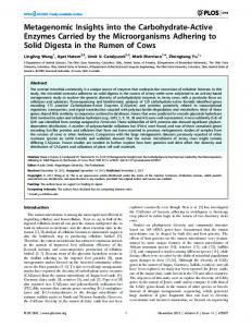
Fig. 3. The value of the combined 0th-order Bessel functions as a function of the frequency, f , and radius, r2 : (a) with two rings: J0 (ϖ) = M1 J02 (ϖ1 ) + M2 J02 (ϖ2 ) and (b) with two rings and a microphone at the center of the ring: J0 (ϖ) = J02 (0) + M1 J02 (ϖ1 ) + M2 J02 (ϖ2 ). Conditions: M1 = 5, r1 = 3.0 cm, and M2 = 5.
20 0 -20 -40 0
4
8
0.0
1.0
2.0
3.0
Fig. 4. The value of the combined 1st-order Bessel functions J1 (ϖ) = M1 J12 (ϖ1 ) + M2 J12 (ϖ2 ) as a function of the frequency, f , and radius, r2 , with two rings. Conditions: M1 = 5, r1 = 3.0 cm, and M2 = 5.
of the combined 0th-order Bessel functions become less deeper and eventually disappear. This is because the zeros of the Bessel functions with different radii occur at different frequencies and, as a result, the combined function generally does not have zeros. It is also seen from Fig. 3(b) that there are no nulls of the combined 0th-order Bessel function appeared in the studied frequency range. This indicates that adding a single microphone at the center of either a CMA or a CCMA can significantly improve the null problems in frequency-invariant beamforming caused by the 0th-order Bessel functions. Similarly, Figs 4 and 5 plot the value of, respectively, the combined 1st-order Bessel function, i.e., J1 (ϖ) = M1 J12 (ϖ1 ) + M2 J12 (ϖ2 ), and the combined 2nd-order Bessel function, i.e., J2 (ϖ) = M1 J22 (ϖ1 ) + M2 J22 (ϖ2 ), both as a function of the radius and frequency. Note that, as discussed in the previous section, adding a microphone at the center of the CCMA can only affect the value of the 0th-order Bessel function, but have no impact on the value of the 1st- and 2nd-order Bessel functions. So, the results of the combined 1st and 2nd-order Bessel functions are the same with or without the center microphone. It is seen that the 1st-order Bessel function has one zero in the studied frequency range but the combined Bessel functions have no zeros. It is observed that the best performance is obtained when r2 is approximately 1.5 cm, i.e., half of the radius of the outer ring. This observation is also true for the combined 2nd-order Bessel functions as seen from Fig. 4. Now, let us check the impact of the radii on the DIs (note that the nulls problem affects the DI and the WNG in a similar way, so we only show the results of the DI here). We consider to design the first- and second-order hypercardioid [47], whose coefficients are given by [ ]T 1 1 1 b2N = 3 3 3 and
[ b2N =
this, let us consider a CCMA with two rings and each ring consists of 5 omnidirectional microphones. We set the radius of the outer ring, i.e., r1 , to 3 cm while vary the radius of the inner ring, i.e., r2 , from 1 cm to 3 cm. For comparison, we consider two cases: in the first one, there is one microphone at the center while in the second case there is no microphone at the center. Figure 3 plots the value of the combined 0th-order Bessel functions as a function of the radius and frequency. The combined 0th-order Bessel function for the case with no center microphone, according to (38), is J0 (ϖ) = M1 J02 (ϖ1 ) + M2 J02 (ϖ2 ). It is J0 (ϖ) = J02 (0) + M1 J02 (ϖ1 ) + M2 J02 (ϖ2 ) if there is a microphone at the center according to (45). As seen, when r2 is equal to r1 (in this case, the CCMA becomes a CMA), two nulls appear in the studied frequency range. As the value of r2 decreases, the nulls
9
1 5
1 5
1 5
1 5
1 5
]T ,
respectively. Figure 6 plots the DIs of the first-order hypercardioid designed by the FIB-CCMAs with and without a single microphone at the center, respectively. As seen, the DI of the FIB-CMA (i.e., when r2 = r1 ) suffers from three nulls in the studied frequency range. This is because the denominators of the filter coefficients are a function of Bessel functions, and the zeros of the Bessel function leads to nulls [36], [37]. Combining with the previous analysis, we know that the first and third nulls are introduced by the 0th-order Bessel function, and the second null is introduced by the 1st-order Bessel function. As the value of r2 decreases, the nulls in DI become less deeper and the best performance is obtained when r2 is approximately equal to 1.5 cm. Theoretically, adding a microphone at the center of the ring can help remove the first and third nulls, i.e., the nulls
IEEE/ACM TRANS. AUDIO, SPEECH, AND LANGUAGE PROCESSING, VOL. XX, NO. YY, AUGUST 12, 2018
20
10
0
0 -10 -20 -40 0
4
8
0.0
1.0
2.0
3.0 -20 0
Fig. 5. The value of the combined 2nd-order Bessel functions J2 (ϖ) = M1 J22 (ϖ1 ) + M2 J22 (ϖ2 ). as a function of the frequency, f , and radius, r2 with two rings. Conditions: M1 = 5, r1 = 3.0 cm, and M2 = 5.
4
8
0.0
1.0
3.0
2.0
0
-10
0
-20 0
-10
-20 0
4
8
0.0
1.0
2.0
3.0
0
-10
-20 0
4
8
0.0
1.0
2.0
3.0
Fig. 6. DI for the designed first-order hypercardioid as a function of the frequency, f , and radius, r2 : (a) FIB-CCMAs with two rings and (b) FIB-CCMAs with two rings and a microphone at the center of the ring. Conditions: θs = 0◦ .
4
8
0.0
1.0
3.0
2.0
Fig. 7. DI for the designed second-order hypercardioid as a function of the frequency, f , and radius, r2 : (a) FIB-CCMA with two rings and (b) FIB-CCMA with two rings and a microphone at the center of the ring. Conditions: θs = 0◦ . 10 8 6 4 2 0 -2 -4 -6 -8 -10 0
1
2
3
4
5
6
7
8
0
1
2
3
4
5
6
7
8
20 10 0 -10
introduced by the zeros of the 0th-order Bessel functions. Indeed, it is clearly seen from Fig. 6(b) that the DIs are further improved when adding a single microphone at the center of the ring. Figure 7 plots the DIs of the second-order hypercardioid with and without a center microphone, where for the case with a microphone at the center of the ring, the inner ring has only three microphones, and the other conditions are the same as in the previous simulation. Similarly, the performance degradation caused by the deep nulls problem can be improved significantly by using multiple rings. In contrast, the DIs in Fig. 7(b) still have nulls at high frequencies, which is caused by the zeros of the 2nd-order Bessel functions. This is due to the fact that the inner ring has only three microphones, so it can only improve the null problem introduced by the 0th- and 1st-order Bessel functions, which further corroborates the theoretical analysis in Section V-B.
-20 -30 -40 -50
Fig. 8. DI and WNG for the designed second-order hypercardioid: (a) DI and (b) WNG. Conditions: θs = 0◦ .
B. Microphones at Different Rings Aligned vs Not Aligned In Section IV, we have shown the structural flexibility of the proposed method that microphones in different rings do not need to be aligned. In this subsection, we compare the effect of microphones at different rings being aligned or not aligned. For reference, we also plot the result with a CMA.
IEEE/ACM TRANS. AUDIO, SPEECH, AND LANGUAGE PROCESSING, VOL. XX, NO. YY, AUGUST 12, 2018
8
0
6
-10
4 -20
2 0 -180 8
-30
-90
0
90
180 0
11
10 8 6 4 2 0 -2 -4 -6 -8 -10 0
1
2
3
4
5
6
7
8
9
10
0
1
2
3
4
5
6
7
8
9
10
20
6
-10
4
10 0
-20
2
-10 -20
0 -180 8
-30
-90
0
90
180 0
-30 -40 -50
6
-10
4 -20
2 0 -180
Fig. 10. DI and WNG for the designed first-order hypercardioid: (a) DI and (b) WNG. Conditions: θs = 0◦ and ψ1,1 = ψ2,1 = 0◦ . -30
-90
0
90
180
Fig. 9. Beampatterns for the designed second-order hypercardioid: (a) FIB-CMA, (b) FIB-CCMA-I, and (c) FIB-CCMA-II. Conditions: θs = 0 ◦ .
We consider to design a second-order hypercardioid. For the FIB-CMA, we use 5 microphones, i.e., M = 5 and r = 3.0 cm. For the FIB-CCMA, there are two rings with M1 = 5, M2 = 5, r1 = 3.0 cm, and r2 = 2.2 cm. We consider two cases: 1) FIB-CCMA-I, microphones at two rings are aligned, i.e., ψ1,1 = ψ2,1 = 0; and 2) FIB-CCMAII, microphones at the two rings are not aligned, i.e., with ψ1,1 = 0, ψ2,1 = 36◦ . The results of the FIB-CMA, the FIB-CCMA-I, and the FIB-CCMA-II are plotted in Figs. 8 (for the DI and the WNG) and 9 (for the beampatterns). It is seen that the FIB-CMA suffers from serious degradation in the DI and the WNG due to the nulls problem. In comparison, the FIB-CCMA has significant better performance. Figure 9(a) plots the beampattern of the FIB-CMA, which is considerably distorted at high frequencies due to the nulls problem. In comparison, the FIB-CCMA (regardless of whether or not the microphones at different rings are aligned) has almost frequency-invariant beampatterns in the studied frequency range, which, again, shows that using CCMAs can mitigate the deep nulls problems. It should be noted that the main advantages of the developed FIB-CCMA are: 1) different rings do not need to have the same number of sensors and 2) microphones at different rings do not need to be aligned. This is very useful in real applications with small and compact apertures.
10 8 6 4 2 0 -2 -4 -6 -8 -10 0
1
2
3
4
5
6
7
8
9
10
0
1
2
3
4
5
6
7
8
9
10
20 10 0 -10 -20 -30 -40 -50
Fig. 11. DI and WNG for the designed second-order hypercardioid: (a) DI and (b) WNG. Conditions: θs = 0◦ and ψ1,1 = ψ2,1 = 0◦ .
C. Performance Comparison Now, we compare the performance of FIB-CCMA with that of FIB-CMA on the design of the first- and secondorder hypercardioid patterns [47]. We consider and compare the following six array configurations. • FIB-CMA-I: UCMA with M = 5 and r = 3.0 cm.
IEEE/ACM TRANS. AUDIO, SPEECH, AND LANGUAGE PROCESSING, VOL. XX, NO. YY, AUGUST 12, 2018
FIB-CMA-II: UCMA with M = 5 and r = 2.2 cm. FIB-CCMA-I: UCCMA with two rings, r1 = 3.0 cm, M1 = 5, r2 = 2.2 cm, and M2 = 5. • FIB-CCMA-II: UCCMA with two rings, r1 = 3.0 cm, M1 = 5, r2 = 2.2 cm, and M2 = 3. • FIB-CCMA-III: UCCMA with two rings plus a microphone at the center, r1 = 3.0 cm, M1 = 5, r2 = 2.2 cm, and M2 = 5. • FIB-CCMA-IV: UCMA plus a microphone at the center with M1 = 5 and r1 = 3.0 cm. Figure 10 plots the DIs and the WNGs as a function of the frequency of the aforementioned six cases for the first-order hypercardioid. It is seen that the two UCMAs suffer from serious degradation in DIs and WNGs due to the nulls problem. Comparing the results of the FIB-CMAI and the FIB-CMA-II, one can see that the nulls problem is more severe for FIB-CMA-I because the increase of the array radius leads to more nulls in the frequency range of interest [37]. In contrast, the DI and the WNG of the FIB-CCMA-I, FIB-CCMA-II, and FIB-CCMA-III are almost frequency-invariant in the studied frequency range, which corroborates that using CCMAs with multiple rings can mitigate the deep nulls problem. It is also worth noting that the FIB-CCMA-III has slightly better DI and WNG performance than the FIB-CCMA-I and the FIBCCMA-II, which shows the advantage of adding a single microphone at the center. The FIB-CCMA-IV still has a null in the DI and the WNG. The underlying reason is that adding a microphone at the center of the ring can only mitigate the nulls problem caused by the zeros of the 0th-order Bessel functions, but the nulls caused by the zeros of the 1stand 2nd-order Bessel functions still exist. The results of the second-order hypercardioid are plotted in Fig. 11. Similarly, the UCMAs suffer from serious degradation in DIs and WNGs due to the nulls problem. The FIB-CCMA-I and FIB-CCMA-III no longer have deep nulls in the studied frequency range. In comparison, the DI and the WNG of the FIB-CCMA-II still have a null at high frequencies (this null is introduced by the zeros of the 2ndorder Bessel functions). This is because that the second ring of the FIB-CCMA-II has only three microphones and it can only mitigate the nulls caused by the 0th- and 1st-order Bessel functions, but has no effect on the nulls introduced by the 2nd-order Bessel functions. As expected, the FIB-CCMA-IV can only mitigate the nulls caused by the zeros of the 0th-order Bessel functions. So, it has two nulls at high frequencies. • •
VII. Conclusions Circular and concentric circular microphone arrays have a broad range of applications and have been used in teleconferencing, telecollaboration, smart speakers/soundboxes, and smart home systems. One of the most important problems in such arrays is the design of broadband, high directive, and robust beamformers that can acquire broadband speech and audio signals of interest
12
while suppressing noise and interference. This paper was devoted to this problem and developed a general approach to the design of beamformers based on an optimal approximation of the beampattern with the Jacobi-Anger expansion. This method can be applied to both circular and concentric circular arrays and can form frequencyinvariant beampatterns with full steering flexibility. In comparison with the algorithms developed previously, the method presented in this paper has the following salient features. 1) Design flexibility: the presented method can be used for either circular or concentric circular arrays with multiple rings and different number of microphones in each ring, and sensors in different rings do not need to be aligned. 2) Full steering flexibility: the beampattern designed by the presented method can be steered to any look direction in the sensors’ plane without distorting the beampattern. 3) Robustness: by using a proper number of microphones and number of rings, the method can form frequency-invariant beampatterns with a high DF and a reasonable WNG, which are both frequency invariant and do not suffer from the problem of deep nulls. By studying four particular cases, i.e., CMAs, CMAs with one microphone at the center, CCMAs, and CCMAs with one microphone at the center, we justified the superiority of the developed method over the existing ones in the literature. We also proved, for the first time in the literature, the functionality of adding one sensor to the center of either a CMA or a CCMA, i.e., it can help improve the deep nulls problem in the DF and the WNG, but can only deal with the nulls caused by the zeros of the 0th-order Bessel functions. References [1] M. Brandstein and D. Ward, Microphone Arrays: Signal Processing Techniques and Applications. Springer, 2001. [2] G. W. Elko, “Differential microphone arrays,” in Audio Signal Processing for Next-Generation Multimedia Communication Systems, Y. Huang and J. Benesty, Eds. pp. 11–65, Berlin, Germany: Springer-Verlag, 2004. [3] J. Benesty, J. Chen, and Y. Huang, Microphone Array Signal Processing. Berlin, Germany: Springer-Verlag, 2008. [4] J. Meyer and G. W. Elko, “Spherical microphone arrays for 3D sound recording,” in Audio Signal Processing for NextGeneration Multimedia Communication Systems, Y. Huang and J. Benesty, Eds. pp. 67–89, Berlin, Germany: Springer-Verlag, 2004. [5] L. C. Parra, “Steerable frequency-invariant beamforming for arbitrary arrays,” J. Acoust. Soc. Am., vol. 119, no. 6, pp. 3839– 3847, 2006. [6] H. Barfuss, M. Mueglich, and W. Kellermann, “HRTF-based robust least-squares frequency-invariant polynomial beamforming,” in Proc. IEEE IWAENC, pp. 1–5, IEEE, 2016. [7] E. Mabande, M. Buerger, and W. Kellermann, “Design of robust polynomial beamformers for symmetric arrays,” in Proc. IEEE ICASSP, pp. 1–4, IEEE, 2012. [8] R. C. Hendriks and T. Gerkmann, “Noise correlation matrix estimation for multi-microphone speech enhancement,” IEEE Trans. Audio, Speech, Lang. Process., vol. 20, no. 1, pp. 223– 233, 2012. [9] D. Kitamura, H. Saruwatari, H. Kameoka, Y. Takahashi, K. Kondo, and S. Nakamura, “Multichannel signal separation combining directional clustering and nonnegative matrix factorization with spectrogram restoration,” IEEE/ACM Trans. Audio, Speech, Lang. Process., vol. 23, no. 4, pp. 654–669, 2015.
IEEE/ACM TRANS. AUDIO, SPEECH, AND LANGUAGE PROCESSING, VOL. XX, NO. YY, AUGUST 12, 2018
[10] Y. Peled and B. Rafaely, “Linearly-constrained minimumvariance method for spherical microphone arrays based on plane-wave decomposition of the sound field,” IEEE Trans. Audio, Speech, Lang. Process., vol. 21, pp. 2532–2540, Dec. 2013. [11] J. Benesty, J. Chen, and C. Pan, Fundamentals of Differential Beamforming. Berlin, Germany: Springer-Verlag, 2016. [12] T. D. Abhayapala and A. Gupta, “Higher order differentialintegral microphone arrays,” J. Acoust. Soc. Am., vol. 136, pp. 227–233, May 2010. [13] S. Markovich, S. Gannot, and I. Cohen, “Multichannel eigenspace beamforming in a reverberant noisy environment with multiple interfering speech signals,” IEEE Trans. Audio, Speech, Lang. Process., vol. 17, no. 6, pp. 1071–1086, 2009. [14] C. A. Anderson, P. D. Teal, and M. A. Poletti, “Spatially robust far-field beamforming using the von Mises (-Fisher) distribution,” IEEE/ACM Trans. Audio, Speech, Lang. Process., vol. 23, no. 12, pp. 2189–2197, 2015. [15] E. D. Sena, H. Hacihabiboglu, and Z. Cvetkovic, “On the design and implementation of higher-order differential microphones,” IEEE Trans. Audio, Speech, Lang. Process., vol. 20, p. 162–174, Jan. 2012. [16] E. A. P. Habets, J. Benesty, I. Cohen, S. Gannot, and J. Dmochowski, “New insights into the MVDR beamformer in room acoustics,” IEEE Trans. Audio, Speech, Lang. Process., vol. 18, no. 1, p. 158, 2010. [17] N. Ito, H. Shimizu, N. Ono, and S. Sagayama, “Diffuse noise suppression using crystal-shaped microphone arrays,” IEEE Trans. Audio, Speech, Lang. Process., vol. 19, no. 7, pp. 2101– 2110, 2011. [18] D. Marquardt, E. Hadad, S. Gannot, and S. Doclo, “Theoretical analysis of linearly constrained multi-channel wiener filtering algorithms for combined noise reduction and binaural cue preservation in binaural hearing aids,” IEEE/ACM Trans. Audio, Speech, Lang. Process., vol. 23, no. 12, pp. 2384–2397, 2015. [19] S. Doclo and M. Moonen, “Superdirective beamforming robust against microphone mismatch,” IEEE Trans. Acoust., Speech, Signal Process., vol. 15, no. 2, pp. 617–631, 2007. [20] G. Huang, J. Benesty, and J. Chen, “Superdirective beamforming based on the Krylov matrix,” IEEE/ACM Trans. Audio, Speech, Lang. Process., vol. 24, no. 12, pp. 2531–2543, 2016. [21] M. Crocco and A. Trucco, “Design of robust superdirective arrays with a tunable tradeoff between directivity and frequency-invariance,” IEEE Trans. Signal Process., vol. 59, no. 5, pp. 2169–2181, 2011. [22] S. Yan, “Optimal design of modal beamformers for circular arrays,” J. Acoust. Soc. Am., vol. 138, no. 4, pp. 2140–2151, 2015. [23] S. Yan, Y. Ma, and C. Hou, “Optimal array pattern synthesis for broadband arrays,” The Journal of the Acoustical Society of America, vol. 122, no. 5, pp. 2686–2696, 2007. [24] G. Huang, J. Benesty, and J. Chen, “Subspace superdirective beamforming with uniform circular microphone arrays,” in Proc. IEEE IWAENC, pp. 1–5, 2016. [25] H. Teutsch and W. Kellermann, “Acoustic source detection and localization based on wavefield decomposition using circular microphone arrays,” J. Acoust. Soc. Am., vol. 120, pp. 2724– 2736, Nov. 2006. [26] E. Tiana-Roig, F. Jacobsen, and E. F. Grande, “Beamforming with a circular microphone array for localization of environmental noise sources,” J. Acoust. Soc. Am., vol. 128, no. 6, pp. 3535–3542, 2010. [27] B. Rafaely, Fundamentals of Spherical Array Processing. Berlin, Germany: Springer-Verlag, 2015. [28] Z. Li and R. Duraiswami, “Flexible and optimal design of spherical microphone arrays for beamforming,” IEEE Trans. Audio, Speech, Lang. Process., vol. 15, no. 2, pp. 702–714, 2007. [29] S. Yan, H. Sun, U. P. Svensson, X. Ma, and J. M. Hovem, “Optimal modal beamforming for spherical microphone arrays,” IEEE Trans. Acoust., Speech, Signal Process., vol. 19, pp. 361– 371, Feb. 2011. [30] T. D. Abhayapala, “Theory and design of high order sound field microphones using spherical microphone array,” in Proc. IEEE ICASSP, pp. 5268–5271, 2008. [31] H. Sun, W. Kellermann, E. Mabande, and K. Kowalczyk, “Localization of distinct reflections in rooms using spherical
[32] [33] [34]
[35]
[36]
[37] [38] [39] [40]
[41] [42]
[43] [44] [45]
[46] [47] [48]
13
microphone array eigenbeam processing,” J. Acoust. Soc. Am., vol. 131, pp. 2828–2840, April 2012. G. Huang, J. Chen, and J. Benesty, “A flexible high directivity beamformer with spherical microphone arrays,” J. Acoust. Soc. Am., vol. 143, no. 5, pp. 3024–3035, 2018. J. Benesty, J. Chen, and I. Cohen, Design of Circular Differential Microphone Arrays. Berlin, Germany: Springer-Verlag, 2015. A. M. Torres, M. Cobos, B. Pueo, and J. J. Lopez, “Robust acoustic source localization based on modal beamforming and time–frequency processing using circular microphone arrays,” J. Acoust. Soc. Am., vol. 132, no. 3, pp. 1511–1520, 2012. S. Chan and H. Chen, “Uniform concentric circular arrays with frequency-invariant characteristics: theory, design, adaptive beamforming and DOA estimation,” IEEE Trans. Signal Process., vol. 55, no. 1, pp. 165–177, 2007. G. Huang, J. Benesty, and J. Chen, “On the design of frequency-invariant beampatterns with uniform circular microphone arrays,” IEEE/ACM Trans. Audio, Speech, Lang. Process., vol. 25, no. 5, pp. 1140–1153, 2017. G. Huang, J. Benesty, and J. Chen, “Design of robust concentric circular differential microphone arrays,” J. Acoust. Soc. Am., vol. 141, no. 5, pp. 3236–3249, 2017. G. Huang, J. Chen, and J. Benesty, “On the design of robust steerable frequency-invariant beampatterns with concentric circular microphone arrays,” in Proc. IEEE ICASSP, Apr. 2018 L. Zhao, J. Benesty, and J. Chen, “Design of robust differential microphone arrays with the Jacobi–Anger expansion,” Appl. Acous., vol. 110, pp. 194–206, 2016. E. Tiana-Roig, F. Jacobsen, and E. Fernandez-Grande, “Beamforming with a circular array of microphones mounted on a rigid sphere (L),” J. Acoust. Soc. Am., vol. 130, no. 3, pp. 1095–1098, 2011. J. Meyer, “Beamforming for a circular microphone array mounted on spherically shaped objects,” J. Acoust. Soc. Am., vol. 109, pp. 185–193, Jan. 2001. S. Koyama, K. Furuya, K. Wakayama, S. Shimauchi, and H. Saruwatari, “Analytical approach to transforming filter design for sound field recording and reproduction using circular arrays with a spherical baffle,” J. Acoust. Soc. Am., vol. 139, no. 3, pp. 1024–1036, 2016. J. Meyer and G. Elko, “A highly scalable spherical microphone array based on a orthonormal decomposition of the soundfield,” in Proc. IEEE ICASSP, pp. II178–II1784, 2002. J. Meyer and G. Elko, “Spherical harmonic modal beamforming for an augmented circular microphone array,” in Proc. IEEE ICASSP, pp. 5280–5283, 2008. S. Koyama, K. Furuya, Y. Hiwasaki, Y. Haneda, and Y. Suzuki, “Wave field reconstruction filtering in cylindrical harmonic domain for with-height recording and reproduction,” IEEE Trans. Audio, Speech, Lang. Process., vol. 22, no. 10, pp. 1546– 1557, 2014. H. L. Van Trees, Detection, Estimation, and Modulation Theory, Optimum Array Processing. Hoboken, NJ: John Wiley & Sons, 2004. J. Benesty and J. Chen, Study and Design of Differential Microphone Arrays. Berlin, Germany: Springer-Verlag, 2012. H. Teutsch, Modal Array Signal Processing: Principles and Applications of Acoustic Wavefield Decomposition. Berlin, Germany: Springer-Verlag, 2007.