Keywords: Design, Context, Sketching, Human Factors. Links: DL. PDF. WEB. VIDEO ..... up or canvas, the users are automatically transported to the book- marked view ... that is very distinct from pencil sketches; we were concerned this.
To appear in the ACM SIGGRAPH Asia conference proceedings
Insitu: Sketching Architectural Designs in Context Patrick Paczkowski†
Min H. Kim†
Yann Morvan§
Julie Dorsey†
Yale University†
Holly Rushmeier†
Carol O’Sullivan§
Trinity College Dublin§
Photographs
Insitu Aerial map
Elevation data
+
Site plan
Interface
(a)
(b)
(c)
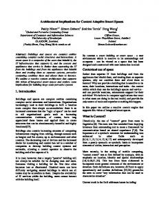
Figure 1: An overview of our approach to presenting context in a lightweight conceptual design system. (a) Input includes site photos, aerial maps, elevation data, and GPS coordinates, from which linked pop-ups and terrain are produced through our novel positioning method, as shown in (b). (c) These representations are used to guide the development of sketches reconciled with the site.
Abstract
1
Architecture is design in spatial context. The only current methods for representing context involve designing in a heavyweight computer-aided design system, using a full model of existing buildings and landscape, or sketching on a panoramic photo. The former is too cumbersome; the latter is too restrictive in viewpoint and in the handling of occlusions and topography. We introduce a novel approach to presenting context such that it is an integral component in a lightweight conceptual design system. We represent sites through a fusion of data available from different sources. We derive a site model from geographic elevation data, on-site point-topoint distance measurements, and images of the site. To acquire and process the data, we use publicly available data sources, multidimensional scaling techniques and refinements of recent bundle adjustment techniques. We offer a suite of interactive tools to acquire, process, and combine the data into a lightweight stroke and image-billboard representation. We create multiple and linked popups derived from images, forming a lightweight representation of a three-dimensional environment. We implemented our techniques in a stroke-based conceptual design system we call Insitu. We developed our work through continuous interaction with professional designers. We present designs created with our new techniques integrated in a conceptual design system.
Computer-aided design (CAD) systems have been extraordinarily successful in design, especially in architecture. Recently there has been considerable interest in 3D modeling systems for early phases in the design of structures. Sketching programs that allow users to rough out three-dimensional definitions from simple strokes and gestures are widely used by architects. Yet even as computers are ubiquitous in the design of the built environment, the existing array of computational aids does not offer assistance in the early conceptual design of structures relative to existing natural and manmade environments – a central concern of architectural design.
Keywords: Design, Context, Sketching, Human Factors Links:
DL
PDF
W EB
V IDEO
Introduction
The design of architectural structures in situ poses substantive and unique challenges. The spatial fit between architecture and its context is a key concern, as architecture includes exterior and interior space [McHarg 1991] and is never designed in a vacuum. There are three basic relationships between architecture and its surround: contrast, merger, and reciprocity. Contrast juxtaposes architecture with the natural context – for example, the relationship of New York’s Central Park to the surrounding fabric. Merger is the opposite of contrast: a building is designed to appear as a harmonious integral part of the surround. Much of Frank Lloyd Wright’s work, including his famous Fallingwater House, shown in Fig. 2, aspired to this condition. Here, the building and context are conceived as one, making it impossible to design independent of the context; such a condition cannot be represented effectively by current CAD systems. Reciprocity represents a hybrid condition, in which a building and its surround reflect one another, and enter into a sort of spatial dialog. The considerations and devices used to achieve these various relationships are numerous, and include such factors as massing, geometry, view(s), and scale, to name a few. There are two current approaches available for representing the surrounding visual context: 3D models and panoramic images. Full 3D models of sites allow a designer to envision designs in multiple views and relative to the context. However, such models are rarely, if ever, used in practice because full-3D models, particularly of landscapes, are difficult to acquire, and the representation is too unwieldy to support conceptual design. Design sketching over pho-
tographic panoramas, either on paper or by computer, is often used due to the intuitive interface. However, these sketches cannot easily be reconciled into a 3D form, and testing the compatibility of locations in the site is challenging, if not impossible. Moreover, this approach is very inadequate when complex topographic variations are involved, and sketching on a photograph does not allow for occlusions or multiple views. At best, it can only support the juxtaposition approach, described above – and only for a single view. A system to support designing relative to context needs to be able to incorporate constraints and features imposed by the existing setting, while allowing free creative experimentation. The key impediment to designing relative to context is the inability to present a complex setting in a form that is amenable to conceptual design. In this paper, we present a suite of techniques to represent context – including terrain information, built structures, and natural features – in a manner consistent with Figure 2: A design in which early conceptual design. We the building and context are implement this representamerged is Frank Lloyd Wright’s tion in a sketch-based system Fallingwater [Sxenko 2007]. that we call Insitu. Building on previous 3D stroke-based sketching systems, such as Harold [Cohen et al. 2000], 3D6B [Kallio 2005], and Mental Canvas [Dorsey et al. 2007], Insitu allows a user to enter strokes on 2D planes, which can be positioned in 3D space to lay out a design. Fig. 1(a) shows the elements of our context visualization method; Fig. 1(b) presents our context representation; Fig. 1(c) displays our system application with an LCD screen tablet. We make the following contributions: • A novel approach to representing a complex site, which enables interactive, conceptual design in situ; • The integration of this representation into a stroke-based sketching system; • A method for fusing data from different sources – including geographic elevation data, on-site point-to-point distance measurements, and images of the site – into a common coordinate system; • A discussion about the iterative development of a design system, based on collaboration between computer scientists and designers.
2
Related Work
We are interested in enabling designers to sketch within the visual context of a site. Understanding context is even more central to design than the ability to produce drawings of design alternatives [Bilda and Gero 2005]. In conventional practice, designers either draw the context within their design sketches, or use acetates to sketch over photographs or on-site drawings. In this section we review previous work on sketching systems for early conceptual design, architectural design in context, site modeling with photographs and publicly available resources for site modeling. Sketching Current CAD software that is capable of preparing final building plans is not suitable for the early phases of design [Chrabin et al. 2003]. To address this issue, simpler and more
intuitive systems have been developed for early design, such as SESAME [Oh et al. 2006] and Google SketchUp [2011]. While simpler than full CAD packages, these are still solid modeling systems. Creating a solid model is fundamentally different from creating a drawing of a particular view of a design. In the early phases, a designer works by, as Schon put it, “having a conversation with the drawing” [Schon 1983]. Free-hand sketching on paper remains the preferred medium. Since Sutherland’s [1964] groundbreaking work, numerous computer interfaces have been proposed to let designers sketch to develop models on the computer [Jorge and Samavati 2011]. A computer allows 3D rather than 2D sketching. The ability to change viewpoint dynamically has been shown to enhance the perception of 3D structures compared to the mental merging of static views [Sollenberger and Milgram 1993; Sando et al. 2009]. Recent work has aimed to marry the computer’s ability to process 3D information with free-hand sketching. Particularly suited to early design are sketch-based systems that allow the evolution of designs from strokes placed in 3D, rather than as sets of 3D solid shapes. In stroke-based systems, such as 3D6B [Kallio 2005] and Mental Canvas [Dorsey et al. 2007], the user begins by creating sketches naturally in 2D, and then is allowed to pull apart and position the strokes in the 2D sketches to begin to suggest a 3D form. Kalnins et al. [2002] developed a sketching system incorporating non-photorealistic rendering (NPR) style strokes in 3D. Just like a blank sketchpad, these systems focus on letting designers start from scratch. Tsang et al. [2004] introduced an image-aided sketching interface system, where 2D images are overlaid to guide user strokes. The system then produces a coarse structured 3D wireframe model. However, these previous systems do not provide a mechanism for modeling the site environments. We build on these stroke-based systems, and in particular take the style of user interactions used in Mental Canvas as the model for our system. Architectural Design in Context The relationship between architecture and its context is a perennial issue [McHarg 1991]. It has become common to use computers to organize contextual documents [Aliakseyeu et al. 2006] for reference during the design process. Documentation of contextual information can be gathered via computer from public sources on the Internet [Stellingwerff 2007]. We build on this work by using publicly available geographic data in creating context.
Chrabin et al. [2003] investigated the use of currently available software to provide visual context in the 3D design space, rather than as peripheral documents used as reference. They found that commodity CAD software created for detailed final modeling is not appropriate in the early stages of design. They stress the importance of simple interfaces and representations for early design phases. In the field of landscape architectural design, Rekittke and Paar [2008] also investigated types of context representation and found it undesirable to mix highly detailed photorealistic representations with incomplete designs. The type of representation used for the existing context should match the representation of the evolving design. We build on this insight by creating representations of site environments consistent with a stroke-based sketching system for design. Modeling from Photographs There has been considerable recent
work in the areas of computer vision and computer graphics to create digital representations of complex natural scenes by processing sets of photographs. This work ranges from organizing sets of photographs in 3D via estimating camera positions with bundling techniques [Snavely et al. 2006] to the reconstruction of entire detailed structures from images [Pollefeys et al. 2004]. Even organized in 3D space, photograph collections are difficult to use to insert novel 3D structures that would be partially occluded in many of the photographs. Reconstructed detailed structures cannot always be reli-
Insitu Building context Input: user site survey, photos, map, GPS
Import an aerial map/ elevation data
Import bundle photographs
Stroke-based sketching in context
Create pop-ups
Output: conceptual sketch design
Figure 3: Schematic illustration of our context-aware sketching system workflow. First, information about the site is gathered by a user in the form of photographs, an aerial map, GPS positions, etc. Then, the ground information from an aerial map/elevation data are imported into the system to form the base of the virtual site. Next, photographs are bundle-adjusted and imported into the system, which yields a lightweight representation, consisting of pop-ups positioned in space. This context representation and visualization are used to guide the development of stroke-based sketching of designs in context and reconciled with the site. ably produced (particularly for natural objects, such as trees), and are computationally demanding for interactive design. The space between just images and full 3D structures has been explored to some extent. Recognizing that full 3D cannot be recovered, Thormahlen and Seidel [2008] used the camera positions and rough geometry recovered using bundler techniques to generate orthoimages to guide design. In an even simpler approach, Lau et al. [2010] developed a system for sketches and markups on a single photo to define a 3D object. Lee et al. [2008] introduced an application to reconstruct incomplete 3D models from architectural drawings with user interaction. These approaches are suitable for modeling individual objects, but not for modeling an environment. An alternative approach to using photographs to produce a lightweight model of a 3D environment is the generation of photo pop-ups. Photo pop-ups combine coarse geometry (planes), textures and transparency. Hoiem et al. [2005] proposed a fully automatic approach to create a pop-up from a photograph. Computers, however, are still no match for humans at scene understanding, and intervention is necessary to correct failure cases. A fully automated approach may also fail to capture the features of concern to a designer. The work of Ventura et al. [2009] is closest to our purpose. Their main contribution consists of an interface for specifying occlusion boundaries. We build on this work by extending the user input for pop-up creation. An individual image pop-up is only a 2.5D representation of a scene. A full 3D representation is needed for architectural design. To address this need, we use multiple linked pop-ups. To position the pop-ups, we use bundle adjustment to position the original photographs. These positions are refined by a local site survey technique, and are tied to global positioning system (GPS) coordinates using publicly available resources. Publicly Available Resources Systems such as Bing Maps and
Google Earth have made rich geographic datasets including aerial photographs easily available to the general public. This data can be used in modeling sites. For example, Google SketchUp 8 [2011] makes it possible to import aerial photographs and city buildings as blocks to use as a site model. However, aerial photographs and block building models alone are not suitable for modeling undeveloped sites with natural features such as rocks and trees. Furthermore, the SketchUp system does not accommodate stroke-based modeling for conceptual design of free-form shapes. To model local sites, many devices that provide GPS coordinates are available at a reasonable cost. A GPS device receives two data values from available satellites: the satellite location and the time of that location. From this data, the device calculates pairwise distances between itself and multiple satellites; triangulation then yields latitude/longitude coordinates of the device. Generally, 6-8 satellites are used for common GPS navigation systems. A high-
end professional GPS device uses ∼15 satellites to provide higher accuracy [Leica 2011]. In theory, a GPS device could be used to produce a site survey. However, the accuracy of consumer-grade satellite navigation devices is coarse and inadequate for architectural applications. Therefore, we enhance the accuracy of the commodity GPS measurements with multi-dimensional scaling.
3
Site Representation
We present a new method for capturing a site environment to be used as context in early conceptual design. Our approach consists of modeling the site topography using local measurements and GPS coordinates, representing site features by creating and positioning multiple image pop-ups positioned relative to the topography, and importing this representation into a compatible stroke-based sketch system. Fig. 3 summarizes our workflow.
3.1
Site Topography
Our goal is to model the local site topography with enough detail to be able to easily locate existing buildings and to support the conceptual design of new buildings. Using aerial photographs from Bing Maps or Google Earth does not generally provide adequate detail, while using range scans to create dense 3D models is inappropriate for use with a conceptual design system. One approach to obtaining a sufficiently-detailed model in universal geographic coordinates is to take measurements at site landmarks using a commodity GPS device, such as an iPhone camera, or a vehicle navigation system, e.g. TomTom. However, these systems have poor accuracy relative to the needs of an architectural site plan, with errors on the order of ∼6m (GPS device) to ∼9m (iPhone) [Zandbergen 2009]. We introduce a method inspired by [Rushmeier et al. 2007], as well as research in Sensor Network Localization [Zhou et al. 2009], to measure the absolute geographical coordinates of feature objects in a site more accurately than using raw GPS coordinates. We use a simple system of stakes that we physically position on the site, similar to stakes used by land surveyors. We create a local model of the topography defined by these stakes by taking linear measurements between stakes and using this to refine coarse GPS measurements. Relative Positioning We take linear distance measurements between all pairs of N stakes. We then use multi-dimensional scaling (MDS) [Borg and Groenen 2005] to find the 3D positions of these points (see Fig. 5 (a)). From the given measurements δi, j , i, j ∈ N, we estimate the unknown three-dimensional coordinates of N points x = x1 , ..., xN ∈ R3 , by minimizing the following objective function f (x) using nonmetric MDS with Kruskal’s stress criterion: � �� �2 f (x) = ∑ �xi − x j �2 − δi, j . i< j
photographs of our measurement stakes, as well as other site photographs, so that we can position the photographs relative to the site topography. Our system enables the conversion of these 2D photographs into multiple pop-ups, as a lightweight visualization of the real world, rather than unwieldy, full 3D objects. Registering Bundles From the set of photographs, the combina-
(a)
(b)
Figure 4: Stake positions with GPS measurements (yellow circles) and dissimilarity measurements (yellow lines) in a rural site (a), with a zoomed-in example stake shown in (b). (b) Coarse GPS positions (latitude/longitude)
(a) Multi-dimensional scaling (relative locations) 2
1
2
1
3 7 8
3
7 5
6 6
4
8
4
5
(c) Standard UTM coordinates (X/Y/Elevation)
(d) Bundle photographs
2
1
2
1
3
3 7
7
8
8 6
6 4 5
4 5
Figure 5: We measure pairwise distances between stakes (a) to estimate their relative XYZ coordinates with multi-dimensional scaling. These coordinates are used to refine coarse GPS measurements of the stakes (b), resulting in more accurate global coordinates (c). The stakes are then used as anchor points to map relative positions of bundled photographs (d) into the UTM coordinate space. Global Coordinate System The result of computing this minimum is a set of three-dimensional coordinates x in a local coordinate system that we wish to relate to global geographic coordinates in the standard Universal Transverse Mercator (UTM) coordinate system. To do this, we take GPS measurements of the stakes with a commodity device, and query the US Geological Survey (USGS) seamless data warehouse [Gesch 2007] for corresponding elevation measurements, giving us rough standard coordinates y = y1 , ..., yN ∈ R3 . We then estimate a 4-by-4 affine transform A by minimizing the following objective function using least squares: g(A) = �y − Ax�22 . The transformed 3D coordinates Ax should have a higher accuracy than the commodity GPS measurements. In addition, this data set includes elevation at a higher accuracy. Note that our use of MDS to refine GPS data differs from the work of Zhou et al. [2009]; they use MDS to estimate ground-truth (2D) sensor node locations for testing the accuracy of standalone GPS.
We merge the refined 3D coordinates with USGS-provided orthoimagery (aerial photographs) and elevation data of the region, given in the form of a geo-referenced bitmap file. Other resources from Google Earth or Bing Maps could be employed as replacements. The elevation data can be used to create a surface that is suitable for rendering through the standard graphics pipeline [Warmerdam 2010]. We convert the elevation data into a height-field terrain mesh, for hidden surface and line removal and user-prompted altitude queries. See Fig. 6 (a) for an example of a landscape site.
3.2
Modeling with Photographs
For context representation, we are inspired by the fact that designers routinely take numerous photographs of a target site. We use
tion of scale invariant feature transform (SIFT) [Lowe 2004] and bundle analysis [Snavely et al. 2006] yields a set of camera intrinsic parameters/positions and sparse, noisy 3D point clouds of features. Among these features are instances of stakes captured in photographs of the site (such as the photograph in Fig. 4). The relative positions of the cameras and points are arbitrarily oriented, similarly to the MDS output in the previous section. We derive a correspondence between the globally-located stakes from Sec. 3.1 and the local stakes (represented as a point cloud) found from the bundle adjustment of the photographs. An affine transform is derived by minimizing the distance error between corresponding global and local stakes, with user assistance to identify the local stakes in the point cloud. Once the bundle-adjusted photographs are situated on the site topography, additional photographs can subsequently be added by the user by marking locations from a top view of the site.
Creating Pop-ups The point clouds from the bundle adjustment are too sparse and noisy to represent the site environment. The images placed in the global coordinates do not allow for 3D viewing, or for designing objects with appropriate occlusion. To better make use of the photographs, we convert them into pop-ups.
An image pop-up consists of four components: a photograph, a virtual camera, a projection plane, and a mask for the photograph. The camera parameters from the bundle adjustment allow us to project the camera’s image (the captured photograph) into one or more projection planes, or canvases, each of which will form the base of a pop-up. The parameters of each canvas are influenced by the outline of the corresponding pop-up (stored as a mask for the photograph). The initial outline can be specified using an interactive image-segmentation tool, shown in Fig. 7(b), which allows users to highlight significant site features, either through painting, or using free-form connected strokes or lines. Users can make refinements to the outline using an interactive foreground extraction graph-cut algorithm [Rother et al. 2004] and an edge-respecting brush [Olsen and Harris 2008]. Once the pop-up outline is finalized, we know which points in the cloud originated from the area of the photograph enclosed by outline. The depth and orientation of the pop-up’s canvas are then found using least squares optimization with these points. See Figs. 6(b) and 7. The canvas has the same properties as a sketching canvas (see Sec. 4). If the depth of the canvas is computed incorrectly, users can transform the canvas to the correct position and orientation, and the pop-up will get re-projected instantaneously. While a dense set of photographs is useful for the bundler calculations, once camera positions are determined, large numbers of photographs become superfluous. Furthermore, not every feature (e.g. every twig and rock) needs to be represented as an individual pop-up. The significant views and features depend on the user’s impression of the site, their design goals, and personal preferences. The user is given the freedom to select an appropriate set of photographs and features for achieving an optimal site visualization.
4
Incorporation into a Sketching System
We have incorporated our site environment representation into a sketching system for conceptual design. Our sketching interface follows the stroke-based sketching applications [Kallio 2005;
for early sessions that used a separate display and tablet, users were presented with the system running on a Windows workstation using a Wacom Cintiq 21UX tablet-display system. We began by creating a sketching system similar to Mental Canvas. In that system, strokes are drawn on 2D planes referred to as canvases. While potentially infinite in extent, the canvas is displayed as a rectangle that expands or contracts to hold the strokes drawn on it. The canvases can be positioned and oriented in 3D space. Individual strokes can be projectively transferred from one canvas to another to evolve a 3D structure from individual 2D sketches. We add images and pieces of images, created in the popup process, to strokes as basic primitives in the system. These are similarly projected onto canvases as described in Sec. 3.2. Furthermore, the site topography is presented as both a textured mesh and as strokes following elevation isolines attached to canvases.
Initial System (a)
(b)
Figure 6: (a) Visualization of the site topography. The black contour lines over an aerial photo represent elevation information at fixed intervals; each contour represents a fixed elevation. This provides designers with more complete geometric information about the site context, which enhances design studies. (b) An example of a pop-up that stands at the average position of feature point clouds from bundle-adjusted site photographs. Close-up view
(a)
An early frustration users encountered with the system was positioning canvases containing their sketches relative to the representation of the environment. In response, we added a technique to position a new canvas relative to a stroke drawn on an existing canvas (representing the approximate intersection of the two planes). We extended this capability by allowing users to move a canvas by dragging its intersection line with any other canvas. We also added cues showing where canvases intersected each other and the representation of the ground.
Canvas Positioning Tools
Pop-up Edge brush
(b)
Figure 7: User interface for creating a pop-up. In (a), the frustum of each camera is displayed on the urban site. The inset in the green box shows the view from the currently selected camera’s frustum. (b) presents the user interface for highlighting a pop-up region to cut out from the chosen viewpoint (a). The green segmentation indicates the preliminary pop-up, created with assistance of the graphcut algorithm. The close-up view shows our edge-respecting brush being used for further edge refinement.
Full 3D Context Early versions of the system used a single image pop-up to give the user a view of the site environment and to draw with occlusions in that view. We found that users did not design in full 3D using the single pop-up. In evolving their design they only examined views very close to the initial view. When viewed in positions far from the original image view, the scale of the design relative to the surroundings was incorrect. This observation resulted in the use of multiple image pop-ups to represent the environmental context, placed into relative positions using the bundler system. Meaningful Scales Initially, we merely provided a visual model
(a)
(b)
Figure 8: An example of preliminary sketching (multicolored forms suspended between buildings) in the urban context. The sketch is presented with (a) photographic and (b) NPR visualization methods. Design courtesy of Janet Echelman. Dorsey et al. 2007]. Like Mental Canvas, our system is an advance over [Tolba et al. 2001], due to free-viewpoint navigation, and the ability to view occlusions and other important spatial effects. However, we found that many modifications and extensions were needed to these basic approaches in order to effectively incorporate our context representation. Rather than being fully specified and then delivered to users, our development approach was to evolve the system through continued user engagement. That is, instead of following a build-and-test paradigm, our system is the result of what has been called “a multi-dimensional, in-depth, longterm case study” [Shneiderman and Plaisant 2006]. In the early months of development, we brought in users who would use the system for short (e.g. an hour) individual sessions. Our users included professional architects, artists, designers, and architecture academics. In later months, the system was used for longer periods, with designs created over multiple sessions. The system is now being used for a real-world design project (a sculpture over a portion of the High Line Park in Manhattan) by professional artist Janet Echelman, and her studio staff. Throughout our engagement with the users, their feedback and input influenced system development. This section summarizes their feedback and the lessons we learned through the entire development and usage of Insitu. Except
of the site environment, with approximate positioning relative to a representation of the site topography. However, the professional architectural users wanted to have quantitative information about the site. In particular, they wanted to see the contextual information presented in meaningful physical length scales. Creating a physically accurate site using just an aerial map and GPS data is challenging, particularly in non-urban sites, due to the lack of detail in maps and the inaccuracy of ordinary GPS devices. Hence we employed a geographical positioning method tied to a global coordinate system, as described in Sec. 3.1. While detailed measurements are not needed in conceptual design, estimates of overall sizes of bounding boxes of designed objects are useful.
Viewpoints and Bookmarks To maintain a simple system interface, our initial system had a single window to show both the site environment and the designed structure together from a single point of view. However, from early user feedback, we learned that users wanted to see the site in multiple views simultaneously. This was not rediscovering the orthographic views used in CAD systems, however. The multiple views of interest are not orthographic, and are site dependent. Moreover, key views are not always clear from the start; the users wished to identify and bookmark key views throughout the design process. Therefore, we modified the layout to show a main and a subsidiary window to visualize the site from two viewpoints simultaneously. Additionally, we placed an easilyaccessible bookmark list with thumbnails of additional views (including the aerial view) on the top of the interface. The bookmark feature has proved to be very popular. Users create lists of interesting and important viewpoints in the 3D site, showing both the design and the context. See Fig. 9 for the user interface (UI).
(b)
Our earlier versions of the sketching interface had a monochromatic stroke, but the all-black strokes too easily blended together and with the photographs of the environmental context. We added color to the strokes and a color brush to paint a surface. Users felt that the color in the strokes helped both with selecting individual strokes while working, as well as giving them more creative control of the design. The painted occlusions helped add texture and depth to their designs.
Strokes
(a)
(c)
(d)
The results we show in the next section were developed with the evolved system, after all of the aforementioned modifications and extensions were incorporated.
5 Figure 9: User Interface. (a) Navigation bookmarks (aerial/site views). (b) The main sketching window. (c) A secondary window displaying the site from a different viewpoint. (d) The control panel for functions in our system. Camera Motion To simulate how people may move through and interact with the structure being designed, we mirror the approach of [Snavely et al. 2006], by providing optional camera motion between two predefined viewpoints. By selecting a bookmark, popup or canvas, the users are automatically transported to the bookmarked view, parent view of the pop-up, or head-on view of the canvas, respectively. Intermediate camera parameters are found by interpolating the initial and final camera poses. Terrain altitude queries are performed to prevent any intermediate camera poses from being underneath the ground. Site Environment Visualization Style We introduced NPR visualization tools to provide site visualizations that are harmonious with the user’s pen strokes. Photographic pop-ups have a visual feel that is very distinct from pencil sketches; we were concerned this visualization would be distracting and overly detailed. Therefore, we needed to provide functions to allow the designer to adjust the appearance of the site environment to their sketch. The contrast between pop-ups and the sketch can be adjusted by changing color saturation. The quantization of colors in pop-ups can be adjusted to give a more painterly effect. Pop-ups can also be selectively hidden if any of them are distracting when seen from a particular view, such as when a pop-up is in between the viewing camera and the sketch. A user can have the system generate strokes on a pop-up’s canvas corresponding to edges in its texture. The user can adjust the sensitivity of the edge detection to vary the number and detail of strokes. Strokes are generated in real time, so that users can quickly browse options to pick the one closest to their intent. To convert the edge image into strokes we use the methods described in [Rosin and Lai 2010] and [Suzuki and Abe 1985]. Fig. 8 compares two different visualizations. These style adjustments can be done per pop-up or for all of them at once. The style of the terrain display can also be adjusted – from an aerial photo of the site to a textured hill elevation.
During the design process, some users prefer to work with photographs because they offer a more realistic sense of the space being designed. Sometimes this is simply to better understand the surrounding environment. At times, the color configuration of the surroundings present ideas for complementary color schemes for the new design. However, for presenting designs to other parties, users may instead be interested in presenting the site environment with an NPR stroke style. Architects often favor NPR for presentation, as it matches the ‘sketchiness’ and flexibility of the designs, emphasizing the point that these designs are early process and are not set in stone.
Results
In this section, we describe results of using the system to create designs on real sites. We first compare three different positioning methods related to the site modeling approach described in Sec. 3.1. Next, we demonstrate our approach with two distinct sites – one rural and one urban. These sites are complementary in their features and are intended to show the range and breadth of our approach. Last, we summarize issues raised by designers upon reflection, after having sketched designs within these sites.
5.1
Positioning Accuracy
We compared the accuracy of three positioning methods – using raw iPhone 4 GPS readings, using readings from a TomTom XL satellite navigation system and using the TomTom readings refined by our MDS method – for 3D geographic location estimates (metric UTM and elevation coordinates) in the rural site (approximate dimensions 60 × 60m2 ). We used a set of 8 stakes within the site, using measured, pairwise distances between the stakes as groundtruth values. We found that the median errors for the pairwise stake distances were 10.12m, 5.93m and 2.20m for the iPhone, TomTom, and MDS methods, respectively. These are indicated by the circle boundaries in Fig. 10(a) and error bars in Fig. 10(b). In other words, the results indicate that the relative distances between stakes is better maintained by estimating locations using our MDS method, rather than using iPhone or TomTom readings directly.
5.2
Designs
Our system has been used for design in both rural and urban settings. Here we show a representative site of each type. In the case of the rural setting, our technique for creating the site topography is essential due to the complex site layout, and the lack of online resources (such as models stored on Google Earth) to represent the site’s features. In the case of the urban setting, while the topography is less relevant, the incorporation of our representation into a stroke-based system is essential because the free-form shape of the sculpture being designed – intended to be compatible with the full existing urban setting – could not easily be sketched out in Google SketchUp or other CAD systems. House in the Woods Fig. 13 shows a design by architect Alexander Chabla for a house in a rural setting, conceived entirely on the computer using our new context representations. The site is a sloping, densely wooded lot. One objective of the design was to place the structure in the landscape in a minimally-invasive way, thereby leaving most of the natural features intact. The massing of the design, which consists of two main wings and an overall shape that is low to the ground, is very responsive to the topography of the site, tightly conforming to the slope. Note that the buildings are occluded by trees, an important objective behind this particular siting.
4587830
Y (UTM) [meters]
6
7 1
1,6 6
4587820
5,8
2,7
8 1 7
5
5 8
4587810
2 4
4
4587800
2
33
4
Aver. iPhone
3
Aver. GPS
(a)
Our Method 4587790 675310 675320 675330 675340 675350 675360 675370 X (UTM) [meters]
70
Aver. iPhone
Aver. GPS
Our Method
Elevation [meters]
65 60 55 50 45 40 1
(b)
2
3
4 5 Stake index
6
7
8
Figure 10: We compare the measurement accuracy of the positions of 8 stakes (in metric UTM and elevation coordinates) in the rural site (approximately 60 × 60m2 ), using measured pairwise distances between the stakes as ground-truth values. The median errors of the three methods – raw iPhone GPS readings, raw TomTom GPS navigator readings and TomTom readings refined by our MDS method – were 10.12m, 5.93m, and 2.20m, respectively, making our method the most accurate in preserving relative distances between stakes. The median errors are represented by the colored circular boundaries in (a) and the error bars in (b). This site was modeled using approximately 60 photographs, from a total of roughly 400 taken. Approximately 30 photos were bundled, most of which were treated as “anchors,” around which other individual photos were positioned as needed. 10 photographs were used in the background; here, entire photos were used as a backdrop. The total site surveying time was about 4 hours; the modeling time, which included some experimentation with applying texture to the terrain, took approximately 7 hours. The next example shows a proposed design, created using Insitu, for an architectural-scale sculpture over the High Line Park in New York’s Chelsea district. The High Line, which sits three stories above street level and snakes its way through the dense fabric of the west side of Manhattan, is a public park, built as a transformation of an elevated, derelict railroad track. The park offers views of the buildings that line the park, as well as expansive views of the surrounding cityscape. We are currently collaborating with artist Janet Echelman, principal of Studio Echelman (Boston, MA), who has designed numerous public sculptures suspended in the context of urban airspace; an example of her previous built work is shown in Fig. 11. Her proposed sculpture will consist of a mesh armature system combined with flexible volumetric forms made of knotted high-technology fabric, and will be suspended from adjacent building using Spectra ropes. Our stroke-based system, as opposed to a solid modeling system, is very well-suited to representing this type of form – and particularly relevant to the urban context, which is represented as a series of linked pop-ups. The design, shown in Sculpture over the High Line
Fig. 14, is strongly influenced by the surrounding context. Therefore, the ability to sketch freely in this context offers a unique understanding of the context, as well as a means to develop the design. In particular, in order to appreciate and relate effectively to the context, the artist, who is very familiar with 3D modeling software, preferred to create initial sketches on linked pop-ups, showing a full view of the scene, rather than using a CAD system and rendering texture-mapped boxes to represent the major buildings in the area. The proposed design, as developed in our system, rises from the site and cantilevers over the rail beds, embracing the existing track, and snakes under an existing building. Additionally, the structure aims to create cinematic views of the cityscape. By draping and fitting the structure to the existing rail bed, the sculpture will be tightly tied to its surrounding buildings. More generally, the artist, in addressing the context, is aiming to highlight the contrast between the city’s industrial past and the Figure 11: An example of the neighborhood’s current develartist’s previous work [Echelopment as a center for conman 2010]. temporary art. To create this site, approximately 45 digital photos were used, from a total of about 400. Here, fewer than five bundled photos were used, as most of the photographs were of individual building facades, and the regularity of the building structures, combined with the help of the aerial view, made individual positioning relatively easy. Here, 6 background photos were used. No stakes or measurements were used here, although spot measurements of the height and width of the High Line would likely have been helpful in retrospect. The total surveying time was 2 hours, while the total modeling time was about 5 hours. In both sites, we used about 70% of the photos for creating popups, and the remaining 30%, either for verifying alignments, or for interesting views. We fully enclosed the landscape site with the background pop-ups, whereas this was unnecessary within the High Line site, owing to the very different nature of the visibility conditions posed by the cityscape.
5.3
Design Reflections
In this section, we briefly summarize comments offered by the architect and artist, who designed the house and sculpture, respectively, described in the previous section. The architect, Alexander Chabla, shared several observations and suggested some useful additional features. First, as is often the case with current practitioners, he makes use of a wide range of software packages in his design process, including AutoCAD, Rhino, and SketchUp, among others. He noted the ability, for the first time, to sketch directly within the context of the site, in spite of the landscape’s tremendous complexity. He felt the ability to work in Insitu relative to a lightweight context could help streamline his process – effectively serving as a one-stop system for initial sketching and mockups. He felt using a single system helped him better integrate his structure into the site – but, more to the point, to be more aware of the site’s potential. He suggested that being able to directly edit the site topography would be a useful addition. (Currently, such “cut-and-fill” edits are most often done in clay or other
Figure 12: A example of sketching-in-progress of a house design sketch in a rural site (in chronological order). Design courtesy of Alexander Chabla.
Figure 13: Multiple views of the completed house design. The rural context is displayed in an NPR style (Left: front view, Right: N◦ / W◦ / S◦ / E◦ in counter-clockwise order from the top-right). Design courtesy of Alexander Chabla.
Figure 14: A proposed design of an architectural-scale fabric sculpture in an urban environment, developed with Insitu (Left: front view, Right: N◦ / W◦ / S◦ / E◦ in counter-clockwise order from the top-right). Design courtesy of Janet Echelman.
Figure 15: Comparing the sculpture design when viewed within a photographic (a) and NPR (b) context visualization. Design courtesy of Janet Echelman.
types of physical models.) He appreciated the ability to apply colors to strokes and used the colors to roughly indicate material choices. He expressed an interest in having a library of strokes corresponding to commonly used building materials, as well as a tool to design and insert additional landscape elements, such as shrubs and trees. He felt that distance and orientation indicators would be helpful, particularly when sketching in the context of a heavily wooded lot. The designer of the sculpture for the High Line, Janet Echelman, noted that when using CAD software, she and her staff are limited by the amount of context they can model and display because modeling their nets is so memory intensive. After developing a couple of different designs, she confirmed that the lightweight representation for site context described in the paper allows for free experimentation in a setting rich in visual content. This capability, as she put it, “opens up new design avenues.” In addition, she noted that an important aspect of her works is the “experience” they create for her audience – how the design interacts with observers visually and spatially, and vice versa. For this reason, she found the camera motion a particularly useful feature to simulate what users would see if they walked around and underneath her sculpture. She and the architect both commented that the ability to sketch in 2D and 3D simultaneously was liberating from a design standpoint. The artist further suggested that exporting a design created in Insitu to SketchUp would be a useful feature, to leverage the functionality available in that package for more refined visual impact.
6
Discussion and Future Work
User experience reports have borne out the value of our lightweight representation of the physical environment, and the utility of our design system, yet many interesting challenges remain. One general observation we have repeatedly noted is that problem-solving in this area cannot be treated with a “one-size-fits-all” approach. Issues of visualization and user-interactivity must leave a certain degree of flexibility to the user to be successful. Not only will design development differ from one designer to another, but even the same architect or artist may employ widely different strategies depending on the details of their project. However, we do believe there are many common approaches, techniques and preferences that can be encapsulated in a design system. Site Creation In our existing representation, on occasion, cam-
eras may get incorrectly registered, and/or pop-ups may get mapped onto incorrectly positioned projection planes. While we do plan to work towards minimizing these errors in the future, a small collection of correctly registered cameras and pop-ups usually suffice to determine if new cameras/pop-ups are inconsistent. Camera positions and pop-up canvases can also be user-adjusted at any point, if necessary. In the future, we would like to allow users to incorporate other accessible data types into the design space, not just their own photographs and elevation data. One example of this is the use of auto-generated panoramic photos, which merit discussion as a complementary representation for the context, particularly for the backdrop of a scene. In general, we do not yet have a well-defined measure for the optimal level of detail of the environment, and how much this can vary across projects.
Context Editing We have found that at times, designers want to
edit the site context – for example, if they plan to cut down a tree or level a hill. To address this, we note that designers tend to share common conventions when drawing landscape features, lighting effects, shadows, building materials, and other aspects of the surrounding context. We plan to synthesize a catalog of these stroke conventions, and leverage them to create a set of context editing tools for our system.
Context Visualization By cataloguing stroke conventions used by architects, we can also gain information about how best to visualize the site context. We have explored some basic NPR representations, but we plan to refine these further in the future, and also develop more intuitive ways for switching between representations. Improvements to Design Datatypes Creating a wider selection of stroke types (pen, marker, charcoal, paintbrush) would be a useful addition. Regarding the canvases, adding basic axial curvature could simplify certain design tasks significantly. The artist expressed interest in having layered canvases, similar to translucent paper, for overlaying different versions of designed facades, or to distinguish between the interior and exterior of building walls. A natural extension of our approach would also allow a designer to refine a conceptual design into a full-3D model. This would tie in with the designers’ requests for providing export capabilities to other design packages, such as Rhino or Google SketchUp. General UI Improvements The designers have also noted that some improvements could be made to our UI, particularly in the area of interacting with existing scene objects (strokes, canvases, etc). One suggestion was to implement a editable scene-graph of the objects in the scene, to be able to easily select, delete and create hierarchies of objects. In addition, the process of transforming objects is still not ideal, and should be made more user-friendly. Creating a Portable System Lastly, the increasingly widespread
availability of tablet computers, such as iPads, could make the basic approach introduced here an appealing means for designers to rough out designs in the field, an approach that is compatible with, but substantially amplifies, the process of visual thinking using pencil and paper.
7
Conclusion
Physical context is a central concern in architectural design, yet it is not accounted for in current CAD software. We have presented Insitu, a first-of-a-kind approach that facilitates conceptual design in the context of an existing complex site. Our method takes as input site photos, aerial maps, elevation data, and on-site point-to-point distance measurements, from which linked pop-ups and a strokebased terrain representation are produced and used to guide the development of design sketches reconciled with the site. User experience reports validate the value of the lightweight representation of the physical environment and suggest broader research directions.
Acknowledgements We are grateful to Xuejin Chen, Katie Bassett, Alexander Chabla, and Janet Echelman and her studio manager, Becky Borlan, for their help with this project. This work was funded by National Science Foundation grants #1044030 and #1018470, a Google Research Award, a Radcliffe Institute Fellowship, and a Science Foundation Ireland grant (StratAG).
References A LIAKSEYEU , D., M ARTENS , J.-B., AND R AUTERBERG , M. 2006. A computer support tool for the early stages of architectural design. Interacting with Computers 18, 4, 528–555. B ILDA , Z., AND G ERO , J. S. 2005. Do we need CAD during conceptual design? In Computer Aided Architectural Design Futures. Springer, 155–164. B ORG , I., AND G ROENEN , P. 2005. Modern Multidimensional Scaling: Theory and Applications. Springer.
C HRABIN , A. M., S ZEWCZYK , J., AND N EUCKERMANS , H. 2003. A critical evaluation of early stages software in its capacity of coping with contextual issues. In Local Values in a Networked Design World. DUP Science. C OHEN , J. M., H UGHES , J. F., AND Z ELEZNIK , R. C. 2000. Harold: a world made of drawings. In Proc. Symposium on NonPhotorealistic Animation and Rendering, ACM, New York, 83– 90. D ORSEY, J., X U , S., S MEDRESMAN , G., RUSHMEIER , H. E., AND M C M ILLAN , L. 2007. The Mental Canvas: A tool for conceptual architectural design and analysis. In Pacific Graphics 2007, IEEE, 201–210. E CHELMAN , J., 2010. 1.26 Sculpture Project at the Biennial of the Americas. http://www.echelman.com/denver.html. G ESCH , D. 2007. Digital elevation model technologies and applications: The DEM users manual. 2nd ed. American Society for Photogrammetry and Remote Sensing, Bethesda, 99–118. G OOGLE I NC ., 2011. SketchUp 8. http://sketchup.google.com/. H OIEM , D., E FROS , A. A., AND H EBERT, M. 2005. Automatic photo pop-up. ACM Trans. on Graph. 24, 3, 577–584. J ORGE , J., AND S AMAVATI , F., Eds. 2011. Sketch-based Interfaces and Modeling, 1st ed. Springer. K ALLIO , K. 2005. 3D6B Editor: Projective 3D Sketching with Line-Based Rendering. In Proc. Workshop on Sketch-Based Interfaces and Modeling, 73–80. K ALNINS , R. D., M ARKOSIAN , L., M EIER , B. J., KOWALSKI , M. A., L EE , J. C., DAVIDSON , P. L., W EBB , M., H UGHES , J. F., AND F INKELSTEIN , A. 2002. WYSIWYG NPR: drawing strokes directly on 3D models. ACM Trans. on Graph. 21, 3, 755–762. L AU , M., S AUL , G., M ITANI , J., AND I GARASHI , T. 2010. Modeling-in-context: User design of complementary objects with a single photo. In Proc. Symposium on Sketch-Based Interfaces and Modeling, 1–8.
ROSIN , P. L., AND L AI , Y.-K. 2010. Towards artistic minimal rendering. In Proc. Symposium on Non-Photorealistic Animation and Rendering, ACM, 119–127. ROTHER , C., KOLMOGOROV, V., AND B LAKE , A. 2004. “grabcut”: interactive foreground extraction using iterated graph cuts. ACM Trans. Graph. 23 (August), 309–314. RUSHMEIER , H. E., X U , C., WANG , B., RUSHMEIER , R., AND D ORSEY, J. 2007. Shape capture assisted by traditional tools. In Proc. Virtual Reality, Archaeology, and Cultural Heritage (VAST), 1–8. S ANDO , T., T ORY, M., AND I RANI , P. 2009. Effects of animation, user-controlled interactions, and multiple static views in understanding 3D structures. In Proc. Applied Perception in Graphics and Visualization, ACM, 69–76. S CHON , D. A. 1983. The reflective practitioner. Harper Collins. S HNEIDERMAN , B., AND P LAISANT, C. 2006. Strategies for evaluating information visualization tools. In Proc. AVI Workshop on BEyond time and errors: novel evaluation methods for information visualization, ACM, 1–7. S NAVELY, N., S EITZ , S. M., AND S ZELISKI , R. 2006. Photo tourism: exploring photo collections in 3D. ACM Trans. Graph 25, 3, 835–846. S OLLENBERGER , R. L., AND M ILGRAM , P. 1993. Effects of stereoscopic and rotational displays in a three-dimensional pathtracing task. Human Factors 35, 3, 483–499. S TELLINGWERFF , M. 2007. Googlized contextual design. In Proc. EAEA, 1–7. S UTHERLAND , I. E. 1964. Sketchpad a man-machine graphical communication system. In Proc. the SHARE design automation workshop, ACM, New York, DAC ’64, 6.329–6.346. S UZUKI , S., AND A BE , K. 1985. Topological structural analysis of digital binary image by border following. Computer Vision, Graphics, and Image Processing 30, 1, 32–46. S XENKO, 2007. Fallingwater, by Frank Lloyd Wright. http://en.wikipedia.org/wiki/File:Wrightfallingwater.jpg.
L EE , S., F ENG , D., G RIMM , C., AND G OOCH , B. 2008. A sketchbased user interface for reconstructing architectural drawings. Comput. Graph. Forum 27, 1, 81–90.
¨ T HORM AHLEN , T., AND S EIDEL , H.-P. 2008. 3D-modeling by ortho-image generation from image sequences. ACM Trans. Graph. 27, 86:1–5.
L EICA, 2011. Leica Reporter38. http://www.leicageosystems.com/reporter/reporter 38/reporter38.pdf.
T OLBA , O., D ORSEY, J., AND M C M ILLAN , L. 2001. A projective drawing system. In Proc. the ACM Symposium on Interactive 3D Graphics, 25–34.
L OWE , D. G. 2004. Distinctive image features from scale-invariant keypoints. Int. J. Computer Vision 60, 2, 91–110. M C H ARG , I. 1991. Design with Nature. Wiley, New York. ¨ O H , J.-Y., S T URZLINGER , W., AND DANAHY, J. 2006. SESAME: towards better 3D conceptual design systems. In Proc. Conf. Designing Interactive Systems, ACM, 80–89. O LSEN , J R ., D. R., AND H ARRIS , M. K. 2008. Edge-respecting brushes. In Proc. User Interface Software and Technology, ACM, New York, 171–180. P OLLEFEYS , M., G OOL , L. J. V., V ERGAUWEN , M., V ERBIEST, F., C ORNELIS , K., T OPS , J., AND KOCH , R. 2004. Visual modeling with a hand-held camera. Int. J. Computer Vision 59, 3, 207–232. R EKITTKE , J., AND PAAR , P. 2008. Real-time collage in landscape architecture. Digital Design in Landscape Architecture, 88–95.
T SANG , S., BALAKRISHNAN , R., S INGH , K., AND R ANJAN , A. 2004. A suggestive interface for image guided 3D sketching. In Proc. the ACM SIGCHI Conference on Human Factors in Computing Systems, ACM, 591–598. V ENTURA , J., D IVERDI , S., AND H OLLERER , T. 2009. A sketchbased interface for photo pop-up. In Proc. Eurographics Symposium on Sketch-Based Interfaces and Modeling, 21–28. WARMERDAM , F., 2010. GDAL - Geospatial Data Abstraction Library. http://www.gdal.org. Z ANDBERGEN , P. A. 2009. Accuracy of iPhone locations: A comparison of assisted GPS, WiFi, and cellular positioning. Trans. GIS 13, s1, 5–25. Z HOU , Y., S CHEMBRI , J., L AMONT, L., AND B IRD , J. 2009. Analysis of stand-alone GPS for relative location discovery in wireless sensor networks. In Proc. CCECE, IEEE, 437–441.


![[PDF BOOK] Architectural Sketching and Rendering ... - Google Sites](https://m.moam.info/img/260x300/pdf-book-architectural-sketching-and-rendering-goo_64783cda097c474e708c9713.jpg)


![[PDF]Read Georgian Architectural Designs and Details - Google Sites](https://m.moam.info/img/260x300/pdfread-georgian-architectural-designs-and-details_6478a051097c4744708d0ad8.jpg)
![([PDF]) Georgian Architectural Designs and Details - Google Sites](https://m.moam.info/img/260x300/pdf-georgian-architectural-designs-and-details-goo_64787d9f097c47a9708ce3bd.jpg)

