to the development of an advanced manufacturing .... Nowadays the manual inspection and verification ..... Figure 17- CATIA design of proposed flexible tool.
Imperial Journal of Interdisciplinary Research (IJIR) Vol-3, Issue-4, 2017 ISSN: 2454-1362, http://www.onlinejournal.in
Inspection Tool for Flexible Manufacturing System Srijith Bangaru Thirumalai Raj M.Sc. in Mechanical Engineering Abstract: The capability to impact quick changeover on an assembling line, starting with one item then onto the next, is a key essential for expanded flexibility. The requirement for nonstop product changeovers and the creation of slighter cluster sizes are getting more important. Furthermore, production lines are ordinarily made up of machines from diverse makers. In the occasion of an item changeover, numerous distinctive settings must be made at these machines. This undertaking describes a set of "configuration for changeover" decides that have been determined from activity exploration, completed inside a mixed bag of segments. Automatic arrangement offers extensive potential for upgrading manufacturing methods and reduced production cost. The research will also investigate the state of the art technologies that can support rapid changeover automation.
1. Introduction By considering the current situation it is pretty much obvious that customer needs to get improved and developed in the field of getting more of personalized and unique kind of products when compared to previous years. During past manufacturing or FMCG companies are afford to manufacture similar kind of products in numbers of thousands and more. But now they are forced to cope up with customer expectations and needs by splitting it in to different number or volume of products by having a brief study on the market. This change leads to the development of an advanced manufacturing system called as the ‘Flexible manufacturing’ system. The flexible manufacturing system deals with the product manufacturing of customized product with thereby reducing the down time between changeovers of each and every product. [1] This helps in companies to launch their new products in to market in a full effective manner. Some of the advantages of flexible manufacturing are:
Manufacturing cost reduction Quality improvement Reduced lead time Increased labor productivity System reliability improvement Machine efficiency improvement Reduced product cost [2]
Since this system comes out with more number of customized products so it is necessary to have a measurement system which have to cope up with the time and also having reduced or minimum downtime. This project concentrates on developing a flexible inspection tool for flexible manufacturing system which can match with the product change over time and increasing the efficiency of the whole manufacturing route and the line. [1]
2. Flexible Manufacturing System It can be defined as a system which has ability to respond accordingly to the change of customer requirements and market forecast. The FMS also deals with the unexpected delays and circumstances and helps in continuing with the manufacturing process. The changes that most influences flexible manufacturing system are dynamic and static changes. The FMS which is designed based on the research that is carried out with the current scenario of changes that prevails in the market and customer needs has its very own limitations. [3] Its ability to respond for the further changes will also be very much low. The FMS which has been designed based on the considerations with the changes in market and also forecasting the future changes and adaptable systems is said to be dynamic FMS.
3. Changeover Time Reduction Lessening changeover time is similar to including limit, expanding productivity and can help most makers in adding a focused edge. Picture a pit group changing the tires on a race automotive. Colleagues pride themselves on decreasing changeover by even tenths of a second on the grounds that implies that their driver is out and about faster and in a finer position to win. The same reasoning applies to assembling – the faster on who is delivering the following produced item, the more aggressive he is. [3]
Imperial Journal of Interdisciplinary Research (IJIR)
Page 387
Imperial Journal of Interdisciplinary Research (IJIR) Vol-3, Issue-4, 2017 ISSN: 2454-1362, http://www.onlinejournal.in
Figure 1. Pit crew changing tires
3.1. Strategies to Reduce Changeover Time
Awareness to decrease changeover time Quick changeover Training to reduce changeover time [4]
3.2. Changeover Time Categories
Figure 2-Categories of changeover time
FORESIGHT: Planning for another step Storage of materials, tools and parts. ATTACHMENT: Attachment of tooling and parts Usage of tools [5] SETTING CONDITIONS: Tooling position Machine settings [5] TRIAL RUNS: “Starting point” adjustments [5]
3.3. Changeover Time Importance
Wastes can be reduced by shortening the changeover time Faster production cycles can be achieved Production flexibility can be increased Changeovers should be safer
Figure 3-Changeover time strategy
4. Mass Customization The term “Mass customization was initially discussed in the book named as “future Perfect” written by Stanley Davis (1987). The mass customization brought many changes in the conventional manufacturing system and operations. Past decades the manufacturing of product was mainly based on the ability of the manufacturers to produce the product. But the scope and concentration is on the customer needs and requirement as a result of heavy completion in the international level. As a result most of the manufacturing companies started to introduce and implement the idea of mass customization in to their manufacturing and operational lines. The understanding of mass customization can be done based on the following study namely: Product design for mass customization Mass customization manufacturing The implementation of mass customization in the field of automobile and aircraft production is been very complicated by considering the complication in designs, manufacturing methods, batch sizes and time to be taken from order to delivery. Hence mass customization is regarded as the continuous and never ending process which deals with the minute and major changes in products and also without much of downtime. [3] [7]
4.1. Single Minute Exchange of Die Process Single Minute Exchange of Die (SMED) is one of the numerous lean manufacturing strategies for lessening time waste in an assembling methodology. It gives a quick and productive method for changing over an assembling procedure from running the current item to running the following item. This fast changeover is key to decreasing generation of lot sizes and consequently enhancing stream. The expression "single minute" does not imply that all changeovers and new starts ought to take stand out
Imperial Journal of Interdisciplinary Research (IJIR)
Page 388
Imperial Journal of Interdisciplinary Research (IJIR) Vol-3, Issue-4, 2017 ISSN: 2454-1362, http://www.onlinejournal.in minute, however that they ought to take short of what 10 minutes. [6]SMED is the term used to speak about the Single Minute Exchange of Die or setup time that can be checked in a solitary digit of minutes. [7] SMED is frequently utilized reciprocally with "brisk changeover". SMED and brisk changeover are the act of diminishing the time it takes to change a line or machine from running one item to the following. The requirement for SMED and brisk changeover projects is more mainstream now than at any time in the past because of expanded interest for item variability, diminished item life cycles and the need to fundamentally lessen inventories. [8] Ohno at Toyota created SMED in 1950. Ohno`s thought was to create a framework that could change the dies in a more expedient manner. By the late 1950`s Ohno could lessen the time that was obliged to change passes on from a day to three minutes. The fundamental thought of SMED is to lessen the setup time on a machine. There are two sorts of setups: internal and external setup. Internal setup exercises are those that might be done just while the machine is ceased, while external setup exercises are those that is possible while the machine is running. [8] The fundamental thought is to make whatever number exercises as could reasonably be expected from inner to outer and likewise inferred that setup lessening is a device which is all around relevant. There has been part of work done in subtle element for the SMED approach in a material transforming industry and likewise recommend that the compelling usage of SMED requires various central prerequisites, these are: cooperation, visual production line control, execution estimation, Kaizen examined about the part of assembling environment in usage of SMED. [8] The relationship in the middle of changeover and creation leveling has additionally been contemplated and closed that as the clump size declines, the expense of each one part will expand, since the changeover time will spread over less parts. This prompts high assembling expenses when changeover times are high and it additionally talked about the subtle element changeover dissection and presumed that in making a part, every level of opportunity of the machine must be pointed out and settled. SMED is likewise utilized as a device to enhance adaptability and the best profit from decrease in changeover time is the capability to deliver parts in more modest clumps. The connection between SMED also supplies outline is likewise associated and it showed that SMED is suitable not just for assembling change additionally for supplies improvement.
5. Inspection in Mass Customization The term inspection denotes the verification of the attributes and measurement so the parts or subassemblies which will go further to constitute a product later in the assembly line to stick with its described dimensions. The ability of the product to retain its desired specification makes it acceptable otherwise it leads to the crap material. The inspection can be carried out based on two kinds of considerations which can be considered as follows: Variable Inspection: This process is mainly involved in checking the dimension and quality attributes of the product which helps in determining the characteristics of the product Attributes Inspection: This type of inspection is based on counting the number of defect parts getting out of each product cycle or batch and deciding on rejection or acceptance of parts based on their quality attributes. The various process that are involved in the inspection process are listed below: Presentation Examination Decision Action [9] With the growth in technology there has been significant development in the field of automation and hence the automated inspection has been used nowadays in more shop floors which tends to increase the efficiency of the products.
5.1. Automated Inspection Nowadays the manual inspection and verification methods are getting replaced by the new technology based automated verification systems. These systems can provide improved efficiency, faster process, flexibility and least error. [10]. By considering economically, installation of automatic inspection will cost very high but it has been made as an investment by considering the labor cost, efficiency, production downtime, exceeding amount of scrap material. [10]. The automated verification system can be performed in three ways as follows: Feeding the products automatically in the production line which leads to the human inspection system where the decision can be taken Manual loading of the parts in to automatic verification system which takes decision regarding the quality attributes of the product
Imperial Journal of Interdisciplinary Research (IJIR)
Page 389
Imperial Journal of Interdisciplinary Research (IJIR) Vol-3, Issue-4, 2017 ISSN: 2454-1362, http://www.onlinejournal.in
Completely automatic system which allows uniform feeding and also decides in the quality attributes of the product and part
The first method can leads to more error than other as it is carried out by the operator and the chances are high to deviate the specifications of the product. While other two processes are involved verification system which is fully automated. [10] Figure 5-Automatic customization [7]
6. Machine Vision
Figure 4-Automatic inspection system layout
5.2. Inspection Positioning OFF-LINE METHOD is the process which does not involve any direct or physical contact of tools and the product and this process is usually carried out on visual based inspection and manual inspection. Inspection cost is high Processing conditions are stable Significance of process and operations are very low
A short presentation of Machine Vision and an understanding of the different definitions and prerequisites of a machine vision are consistently advanced in this part. An understanding of the fundamental phrasing of machine vision is essential since the ensuing piece of the report manages the configuration and coordination of a flexible measurement tool that utilizes of machine vision. Machine vision innovation makes utilization of camera and picture preparing to help take estimations to keep up the obliged quality guidelines. Machine vision these days are for all intents and purpose utilized as a part of very accurate and various sorts of assembling commercial ventures to automate the production in this way expanding the manufacturing rate and yield. The various steps that are involved in machine vision are as follows: Capturing the image Analysis and processing Interpreting the results Taking decision based on the results generated [11]
ON-LINE METHOD, in this method usually the verification process is carried out only after completion of the manufacturing step. The measurement systems which are operated through probes are best examples for this method. [9]
Figure 6- Steps in machine vision
6.1. Applications of Machine Vision Although the machine vision has its application in various fields some of its major usage are as follows: Locating Measurement
Imperial Journal of Interdisciplinary Research (IJIR)
Page 390
Imperial Journal of Interdisciplinary Research (IJIR) Vol-3, Issue-4, 2017 ISSN: 2454-1362, http://www.onlinejournal.in
Inspection Reading
LOCATING: In this particular part the machine vision helps to determine the location, co-ordinates and alignment of the particular component at the space [11] Figure 10- Reading the data
6.2. Machine Vision Cameras
Figure 7-location
MEASUREMENT: The machine vision also plays an important role in determining the dimensional quality and attributes of the part and product to ensure its efficiency before it reaches the market
There are generally three types of cameras that are generally employed in order to carry out the machine vision process in the industries: Vision sensors Smart camera Camera based on PC Past decades the cameras employed were mostly analog. But the above said cameras operates in a digital manner which ensures improved focal clarity, stabilization and enhanced accuracy. [11] VISION SENSORS: The main purpose of utilizing the vision sensors is to perform only the predetermined and preloaded tasks which were encoded on it. These cameras are usually used to determine the product based on its geometry, color and the shape of the component.
Figure 8- Measurement
INSPECTION: The machine vision also helps in analyzing the whole component or part in order to determine its defects, flaws or cracks on the surface of the component and it can be rejected in the production line itself. This process ensures the consumers with high quality components. [11]
Figure 11- Vision sensor cameras
Figure 9- Inspection
SMART CAMERAS: These cameras are consolidated with an inherent unit for picture examination which permits these cameras to take and dissect a picture for the obliged results, attributes and parameters making them a flexible apparatus for a wide assortment of uses.
READING: This is defined as the ability of the machines to read the data which can be 1D or 2D which helps in the measurement systems in decision making. [11]
Figure 12- Smart cameras [12]
Imperial Journal of Interdisciplinary Research (IJIR)
Page 391
Imperial Journal of Interdisciplinary Research (IJIR) Vol-3, Issue-4, 2017 ISSN: 2454-1362, http://www.onlinejournal.in PC BASED CAMERAS The main objective of this camera is to capture data from the component and which is transferred to the computer which converts it in to the human readable form with lot more details. [11]
Figure 13- PC based camera inspection system
The above image illustrates that the image capture and processed with help of a PC based camera system gives an idea about the number of components and also its position and volume.
7. Motivation for Proposed System In the past decades the manufacturing systems are afford to manufacture the same kind of products and parts with their specified set of dimensional and quality attributes since there are no much competitors prevailing in the market. Post the world war scenario the market for the products get expanded all over the world and the attributes of the products which were previously defined by the manufactures starts to get based on the ideas and the interests of the customers who pays for the product. When the design and quality attributes control gets changed over to the customer, whom can be of various nations and they can also have their very points of interests on a particular products. This forces the manufacturer to obtain inputs of idea and to perform brief researches on the market in order to get knowledge about certain ideas about set or group of people and starting to forecast the future ideas to be implemented on the market. These scenarios give rise to various advancements in manufacturing such as lean manufacturing, flexible manufacturing, mass customization, reconfigurable manufacturing systems. The reconfigurable and flexible manufacturing systems are of similar concepts which has ability to adapt the manufacturing systems various operations and tasks so that products of different quality and dimensional attributes can be produced at the same production line. Although the initial cost for the installation of these systems are higher it can be considered as oneoff cost which helps the manufacturers to prevail among completion and to fulfill the various requirements of the customers.
The inspection and verification systems which are equipped at the traditional or conventional manufacturing systems cannot support the products that are manufactured in FMS. So it is required to install inspection system which has to be constituted of various advancements in order to support the products with different attributes. During the past decade the term named “Mass Customization” become more common among the manufacturers as a result of grown participation of customer ideas during the designing and manufacturing a new component. For example if we consider automotive industries in past years manufacturers used to manufacture two or three variants in a particular vehicle. But nowadays the customers are given freedom to choose and customize the look and almost all outer parts of a vehicle to their taste. Some of the customers can choose vintage style and go with old and classic looking variant. Some may opt for freakish looking variant of the same vehicles. Mass customization is a new concept which has been developed as an advancement for FMS to manufacture various batches of products with various designs and dimensional attributes with very small volumes of batch sizes. By comparing to the inspection system which is employed at the FMS, the inspection system at a manufacturing line utilizing the concept of mass customization should be highly advanced since the product attributes are going to be different which give rise to larger number of batches with lower volumes. So it’s required by the inspection system of high adaptability and quickly response for the change of products in least possible time. As said before changeover time is the down time that the manufacturing line was forced to stop its manufacturing of its product in order to support the delay in tooling or setup of the inspection system to get configured for the change in products attributes. Hence it is important to build an automated verification system which can reduce the changeover time and support the mass customization in an effective manner. For the building of this flexibility tool proper literature review is made to study the importance of implementing the mass customization and FMS in the production line. With the methodology part knowledge about various advancement in the field of metrology is understood by performing case study on various advanced measuring instruments. The technology that can be incorporated in to the development of a new system is also understood. The various objectives to achieve better flexible verification tool thereby reducing the downtime is explained in the next section.
Imperial Journal of Interdisciplinary Research (IJIR)
Page 392
Imperial Journal of Interdisciplinary Research (IJIR) Vol-3, Issue-4, 2017 ISSN: 2454-1362, http://www.onlinejournal.in 7.1. Objectives of the Proposed System
To develop or alter an existing inspection system in flexible one which has very least changeover or down time. Developing a new flexibility system with advanced sensors to make it more flexible Providing suggestions for the existing inspection systems to make it further flexible While designing the new flexible tool the factor of costing is also kept in mind to make the system more affordable.
7.2. Ideas for Designing New System The basic design for developing new flexible tool which has reduced downtime is obtained from the non-contact automated measurement system. The illustrative image that shows the non-contact and automated measurement system is shown below.
direct contact with the part or components in order to get data. But in the case of non-contact measurement system the extensive use of laser and image capturing technologies ensures that the inspection is carried out without any contact between the probe and the component. Some of the advantages of using non-contact measurement systems are: Higher measurement rate when compared with the contact measurement system Improved accuracy because of the usage of optical instruments Ability to achieve higher accuracy irrespective the environment of working Higher stability and rigidity Much more flexible than the contact measurement system
7.5. Layout of Proposed System The layout of the proposed flexible tool can be interpreted through the following flow chart comprised of various elements and components
Figure 14- Non contact automated measurement system
7.3. Reasons for Choosing Automated Systems
Higher range of accuracy when compared with the analog or manual measurement system Downtime can be reduced with implementation of codes such as bar codes to send commands and to load the predefined data for the upcoming products on the production line Measurement rate is high when with compared manual or analog measurement system Flexibility of the measurement system can be improved
Figure 15- Layout of the flexible tool physical design
The chosen components are made sure to share a common software language or commanding software so that the codes which can be generated for performing the specified set of operations can be carried out on system. It is clear from the specifications that the Visual Basic programming language codes can be employed so that the operations in the following flowchart can be done by using the proposed flexible tool in an effective manner.
7.4. Reasons for Choosing Non-Contact Measurement System The latest measurement systems available employs both contact and non-contact measuring technologies. Probe will be provided in the case of contact measuring instruments which will have a
Imperial Journal of Interdisciplinary Research (IJIR)
Page 393
Imperial Journal of Interdisciplinary Research (IJIR) Vol-3, Issue-4, 2017 ISSN: 2454-1362, http://www.onlinejournal.in
Figure 17- CATIA design of proposed flexible tool [13]
Figure 16- Flowchart for the operation in proposed flexible tool design
MATLAB software should also employed for the purposes of the image acquired using the sensors which tends to convert it in to grey scale for furtherer deeper inspection and verification.
7.6. Design of the Proposed System The various components to be included in the newly proposed design in order to perform its complete functions and operations are as follows: Customized material handling system in order to transport the products in the production line Sensor positioning system which should be able to position and alignment of the product which has to be verified and inspected Separate system for identifying the parts which will help in choosing the preloaded data for the upcoming product based on accessing the specific codes printed on the products. Some rough designs are made which can incorporate the above components are made as a rough sketch and necessary modifications are made for the final one. The finally chosen framework of the proposed tool system that is designed with the help of CATIA designing software is presented below.
Figure 18- Drafting of the flexible tool [13]
The above shown design was made in CATIA and some dimensions which were considered for designing this flexible tool frame work are 1000mm X 725mm X 750mm. The material applied for designing the design was aluminum bars which can be purchased as per our requirements and since the strength, reliability, durability and stiffness were high when compared with other material I opted for constructing the design with aluminum bars and rods. The design was also provided with housings for the drive motor which makes the sensor to be mobile. The vertical and horizontal motions are made possible by connecting the drive motor along with the screw mechanism. Because of this both horizontal and vertical motion can be achieved without any collision. While constructing the design another aspect kept in mind was to provide a complete 3600 capability of the sensor to inspect the part proceeding the production line. [14]
Imperial Journal of Interdisciplinary Research (IJIR)
Page 394
Imperial Journal of Interdisciplinary Research (IJIR) Vol-3, Issue-4, 2017 ISSN: 2454-1362, http://www.onlinejournal.in The servo motor is required in order to make the screw mechanism and the sensor which has been provided in the proposed design of the flexible tool. Controller has to be provided in the circuit so that the pre-defined data and attributes of the product can be compared through the sensor and the data can be transferred to the controller in order to take an immediate action regarding the quality of the product. For this purpose the research has been carried out to find the best available servo motors and the micro controllers which can support the newly proposed flexible tool. [14] [12] At the end IBE series of servo motor manufactured by the PARKER system is decided to be the best available option because of its advanced specifications which can be incorporated with micro controllers and designed specifically for material handling systems. [14]
data of 24 products without greater changeover time to take place. Specialized in performing multitasking also remains as an added advantage for choosing this controller for performing various signal processing in the system. [14]
7.7. Specifications of Components Servo Motor: The specifications of different variants available in the IBE series of servo motor is shown below and based on our requirements iBE232F variant is chosen because of its maximum peak torque level which makes the system more reliable. Selecting the appropriate controller is very much crucial because it can make the flexible tool system much more flexible and to respond quickly towards the product changeover in the production line.
Figure 20- Specifications of multi axis motion controller ACR 9000 [14]
Figure 21- Order code for ACR 9000 controller [14]
Vision Sensor: The next important step is to choose an ideal sensor which can perform the inspection and verification task in the newly proposed flexible tool. Sick system has been considered as one of the pioneers in providing the solutions for the industries particularly for product inspection by designing many machine vision sensors which can support different kinds of measurement, verification and inspection systems. Figure 19- Specifications if IBE motors [14]
Multi-Axis Motion Controller: The specifications of the ACR 9000 multi axis motion controller is shown below which can support up to
Imperial Journal of Interdisciplinary Research (IJIR)
Page 395
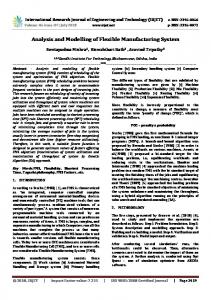
Imperial Journal of Interdisciplinary Research (IJIR) Vol-3, Issue-4, 2017 ISSN: 2454-1362, http://www.onlinejournal.in The recommended system can also result in improving the inspection rate and also it will reduce the labor cost to a greater extent. The proposed system has a constraint of testing the objects with certain dimensional limits but introducing the robotic arm improves the dimensional limits. Thereby object from very low rang to higher range in terms of dimensions can be inspected using the proposed system. Figure 22- PIM60 Vision sensor [11]
The above shown image illustrates the PIM 60 sensor which can be included in the flexible tool because of its much more flexibility and extensive use in the field of automated verification and measurement systems. The ability to determine the parts because of its integrated code reader makes it much faster and reliable. Figure 24- Robotic arm supporting measurement systems
The above image illustrates the incorporation of the proposed design along with a robotic arm thereby improving its overall performance. The future work of this project can be based on performing or implementing the flexible tool system in wide range of industries like FMCG, garments etc.
9. Conclusion
Figure 23- Specification features of PIM 60 Visual sensors [14]
8. Future Recommendations The proposed flexible tool got lot of constraints such as cost, time and resources. The incorporation of the proposed flexible tool along with a robotic arm which can form a perfect flexible system for supporting rapid product changeover. This can provide higher mobility level of the visual sensor ensuring the accuracy and effectiveness of the system.
This project concentrate lot about understanding the concepts of flexible manufacturing, mass customization and reconfigurable manufacturing system. The brief study about various strategies involved in mass customization and FMS are also studied in detail. The various measurement systems that are available and advanced technologies that are implemented in the metrology field were researched in detail. Various measurement instruments like FARO laser scanner, FARO arm, CMM were used to perform case study in order to gain knowledge about their working methodology. As a result of knowledge gained through literature review and working methodology design for the proposed Flexible tool which can support rapid product changeover is made. The components to be included in order to make the system more flexible were found out and its details and specifications were mentioned. This project helped me in gaining extensive knowledge about the field of metrology and its extensive growth in the field of manufacturing and production. This project also gave me opportunity to get some hand on various advanced measurement systems and also the software’s to gain knowledge from it.
Imperial Journal of Interdisciplinary Research (IJIR)
Page 396
Imperial Journal of Interdisciplinary Research (IJIR) Vol-3, Issue-4, 2017 ISSN: 2454-1362, http://www.onlinejournal.in
10. Acknowledgements This effort will not get complete without bestowing my thankfulness for each and every one who has supported and encouraged me to complete this project, First I have to thank my parents who showed extensive support towards my development and for showing their unconditional blessing on me. I should also thank all my classmates and friends who gave constructive ideas and motivation for me to complete this project in time. I should also thank COVENTRY UNIVERSITY for their academic support for this all important project in my Master’s Degree. Special and sincere thanks to Professor Jafar Jamshidi for his guidance to complete my project and without him it will be of not possible.
[12] L. Geosystems, "Leica Geosystems," 1993. [Online]. Available: http://ptd.leicageosystems.com/en/Products_885.htm. [Accessed 28 July 2014]. [13] CATIA, "Screen shots," DASSAULT SYSTEMS, 2014. [14] Parker, "Controller," Cleveland, 2012.
11. References [1] R. P. Parker, "Manufacturing ¯ exibility: Measures and relationships," University of Michigan, Victoria, 1998. [2] A. K. SETHI, "Flexibility in Manufacturing: A Survey," Kluwer Academic, Toronto, 1990. [3] G. Qiao, "Flexible Manufacturing System for Mass customization," Gaithersburg, 2002. [4] M. Resnick, "Design Principles for Tools to Support Creative," Carnegie Mellon University, 2005. [5] S. Dave, "Lean Thinking," SMED Literature review, 2012. [6] G. C.Tomlin, "Leaders for manufacture program," Enabling manufacturing flexibility, 2008. [7] P. S. G. N. Dave Alford, "Mass customization - an automation perspective.," International Journal of Production Economics, vol. 65, no. 1, pp. 99-110, 2000. [8] A.R.Mileham, "International Journal of Operations & Production Management," Operations & logistics management, pp. 185-196, 2007. [9] M. Aslam, "Indira Gandhi National Open University," 1987. [Online]. Available: http://www.ignou.ac.in/upload/UNIT%202-55.pdf. [Accessed 15 July 2014]. [10] M. Amir, "Agile manufacturing-The next step," Benchmarking; An international journal, vol. 8, no. 2, pp. 132-143, 2001. [11] E. Sick, "SICK Sensor Intelligence," 2006. [Online]. Available: http://www.sickivp.com. [Accessed 30 July 2014].
Imperial Journal of Interdisciplinary Research (IJIR)
Page 397