Feb 1, 2008 - arXiv:cond-mat/0008092v1 [cond-mat.supr-con] 6 Aug 2000 ... ductors [1â6], and the associated instabilities [7â24], have recently attracted ...
Instabilities and disorder-driven first-order transition of the
arXiv:cond-mat/0008092v1 [cond-mat.supr-con] 6 Aug 2000
vortex lattice Y. Paltiel1 , E. Zeldov1 , Y. Myasoedov1 , M. L. Rappaport1 , G. Jung1,2 , S. Bhattacharya3,4 , M. J. Higgins3 , Z. L. Xiao5 , E. Y. Andrei5 , P. L. Gammel6 , and D. J. Bishop6 1 Department
of Condensed Matter Physics, Weizmann Institute of Science, Rehovot 76100, Israel
2 Department 3 NEC
of Physics, Ben-Gurion University of the Negev, Beer-Sheva 84105, Israel
Research Institute, 4 Independence Way, Princeton, New Jersey 08540 4 Tata
5 Department
Institute of Fundamental Research, Mumbai-400005, India
of Physics and Astronomy, Rutgers University, Piscataway, New Jersey 08855
6 Bell
Laboratories, Lucent Technologies, Murray Hill, New Jersey 07974 (February 1, 2008)
Abstract Transport studies in a Corbino disk geometry suggest that the Bragg glass phase undergoes a first-order transition into a disordered solid. This transition shows a sharp reentrant behavior at low fields. In contrast, in the conventional strip configuration, the phase transition is obscured by the injection of the disordered vortices through the sample edges, which results in the commonly observed vortex instabilities and smearing of the peak effect in NbSe2 crystals. These features are found to be absent in the Corbino geometry, in which the circulating vortices do not cross the sample edges. PACS numbers: 74.60.Ec, 74.60.Ge, 74.60.Jg
Typeset using REVTEX 1
The nature of the disorder-driven solid-solid transition in the vortex matter in superconductors [1–6], and the associated instabilities [7–24], have recently attracted wide attention. A number of anomalous instability phenomena were reported, which include memory effects [7], frequency and bias dependence [7–9], low frequency noise [10–12], history dependent response [13–22], slow voltage oscillations [11,23], and negative dynamic creep [24]. NbSe2 is a very convenient system for studying these phenomena since it displays a pronounced peak effect (PE) in the critical current Ic below the upper critical field Hc2 . The PE constitutes a transformation of the quasi-ordered Bragg glass phase [1–4] below the PE, to a highly disordered phase in the PE region [25]. Although several sharp features have been observed at the PE [15,16,19] and various models for the PE suggested [5,19], there is currently no general consensus regarding the underlying nature of the disordered phase (DP) and of the corresponding order-disorder transition. An important property of the disorder-driven transition is that the DP can be ‘supercooled’ to well below the transition by a field-cooling procedure, where it remains metastable in the absence of driving currents [14–19]. In this Letter we address the question of how the metastable DP modifies the apparent transport behavior and what are the actual underlying vortex matter properties in the absence of the metastabilities. Our study is motivated by a recent model, according to which the metastable DP can be formed dynamically by an edge-contamination mechanism [9]. In the presence of a driving current, the flowing vortices have to penetrate into the sample through the surface barriers at the edges [26]. Since the barrier height is non-uniform due to material imperfections, the vortices are injected predominantly at the weakest points of the barrier, hence destroying the ordered phase (OP) and creating a metastable DP near the edges. Consequently, the common experimental procedures inadvertently cause a dynamic admixture of the OP with the metastable DP, thus preventing observation of unperturbed OP and of its behavior in the vicinity of the transition. We have carried out transport measurements in a Corbino disk geometry (inset to Fig. 1), in which the vortices circulate in the bulk without crossing the edges, and hence the injection of the DP could be prevented. These measurements are compared with the regular 2
strip configuration in the same crystals. If the instability effects are a bulk phenomenon, no significant difference between the two geometries is expected, whereas if the sample edges do play a dominant role, qualitatively different behavior should be observed. This paper demonstrates that the two geometries yield strikingly different response and, significantly, the instability effects are eliminated in the Corbino geometry. Furthermore, by removing the complicating effects of the edges, the true bulk dynamics in the vicinity of the transition can be probed for the first time. The results suggest that the disorder-driven transition TDT is possibly a thermodynamic first-order phase transition. In addition, it is found that the TDT line displays a sharp reentrant behavior at low fields in a wide temperature range. The results presented here were obtained on a Fe (200ppm) doped 2H-NbSe2 single crystal 2.2 × 1.5 × 0.04 mm3 with Tc =5.7 K, which display a significantly broader PE as compared to the pure crystals [7,15]. Similar data were obtained on three additional samples including one pure crystal. The crystals were cut with a very fine wire-saw to ensure uniform edges. Ag/Au contacts were evaporated through a mask designed for a comparative study of the Corbino and strip geometries on the same crystal, using the same voltage contacts +V,-V (Fig. 1 inset). When measuring the Corbino, the current is applied to the +C,-C contacts, while for the strip configuration the +S,-S contacts are used. To prevent vortices from crossing the edges it is crucial to enforce a uniform radial current in the Corbino. The current uniformity is limited by the variations in the local contact resistance along the outer ring electrode. In order to improve the current uniformity, the ring electrode is divided into four quadrants, and 1/4 of the current is applied to each quadrant. Without such a careful current balance, some of the vortices are injected through the sample edges resulting in metastability effects similar to the strip configuration. The Corbino and the strip geometries were usually compared at the same applied current. In both geometries the current density is not uniform throughout the sample. A calibration above Tc shows that the average current density between the +V,-V voltage contacts is higher by about 25% in the strip configuration, consistent with a geometrical calculation. Therefore, all voltage readings (V ) of the strip were divided by about 1.25 in order to obtain the same voltage 3
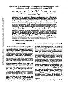
above Tc in the two geometries. Similarly, the Ic values of the strip were multiplied by the same factor. The ac measurements were limited to frequencies below 1 kHz to ensure that there were no effects of finite skin depth. The temperature reproducibility between different runs was about 30 mK. Figure 1a shows the critical current vs. temperature measurements in the vicinity of the PE at 2 kOe. The striking difference between the two geometries is evident. While the dc Ic in the strip geometry shows the usual smooth PE, the Corbino Ic displays a very sharp drop at the maximum of the PE. Similarly, Fig. 1b shows the voltage at a constant current at 2.5 kOe, which displays a very sharp drop at TDT in the Corbino, for both dc and ac currents. Within our temperature reproducibility the response in the Corbino is practically frequency independent in the entire field and temperature range, as expected in the absence of the instability phenomena. The sharp transition in the Corbino geometry reflects a disorder driven transition TDT between two thermodynamically stable phases: an OP below TDT , which is dominated by the elastic energy and is characterized by a low critical current Jcord , and a DP above TDT , which is governed by the pinning energy and has a high Jcdis . We now analyze the transport behavior in the strip geometry. Figure 1 shows that the system has a conventional response with no geometry and no frequency dependence above TDT . This is where only one stable phase, the DP, is present. In contrast, the region below TDT is where all the anomalous phenomena in the strip configuration are found [7–24]. In this region, in the presence of a driving current, a metastable DP is injected through the sample edges instead of the equilibrium OP [9,21]. The driven metastable DP has a finite lifetime, τr , that defines a characteristic relaxation length Lr =vτr , over which the metastable DP anneals into the OP (v is the vortex drift velocity). As a result, the measured dc Ic in the strip is a weighted superposition of Jcord with the metastable Jcdis , RW given by Ic = d 0 Jc (x)dx ≃ dLr Jcdis + d(W − Lr )Jcord , where d and W are the sample thickness and width [9]. For Lr ≪ W we obtain Ic = dW Jcord , and Ic = dW Jcdis for Lr ≥ W . The relaxation length Lr is very sensitive to the proximity to the transition. Near TDT the elastic and the pinning energies are comparable, and therefore the metastable DP has a long 4
lifetime, and hence Lr is large. Further below TDT the driven DP becomes progressively unstable, and therefore Lr drops continuously at lower temperatures, resulting in a smooth decrease of Ic in the strip [27]. Since Lr starts to decrease immediately below TDT , the maximum in Ic of the strip coincides with TDT , as seen in Fig. 1a. The enhanced Ic in the strip below TDT causes the dc voltage response to be significantly suppressed and shifted to lower temperatures compared to the Corbino, as seen in Fig. 1b. This voltage has a smoother temperature and field dependence due to the gradual evolution of the effective Ic in the strip. The edge contamination also results in a very pronounced frequency dependence below TDT . An ac driving current limits the contamination by the DP to narrow regions, of width xac d , near the edges of the strip, where the vortices penetrate and exit during the ac cycle [9]. Since xac d ≤ Lr , the Ic measured by an ac current in the strip is significantly reduced relative to the dc measurement, as shown in Fig. 1a. Also, since xac d shrinks with frequency, the voltage increases with frequency and is shifted towards the response of the Corbino as shown in Fig. 1b. The combination of the observed differences in the ac and dc properties below TDT in the two geometries, as presented in Fig. 1, cannot be attributed to any known bulk vortex mechanism or inhomogeneities, and clearly demonstrates the key role of the sample edges. The location of the disorder-driven transition line TDT or HDT on the H − T phase diagram, derived from the Corbino data, is shown in Fig. 2. Striking reentrant behavior of HDT is observed. At elevated fields, the elastic energy decreases with field resulting in the high-field HDT line when it becomes equal to the pinning energy. The recent theoretical studies of the disorder-driven transition have mainly focused on this high-field HDT transition [1–4]. However, the elastic energy also decreases rapidly at low fields where the vortex interactions start to decrease exponentially, which leads to a mirror-like reentrant HDT line [1,4,5]. Similar arguments involving thermal fluctuations lead to the well known prediction of reentrant melting [28]. Although observations of a reentrant PE were originally interpreted in terms of reentrant melting [29], subsequent studies attribute this behavior to a reentrant 5
disordering of the lattice [30]. Our results demonstrate the first unambiguous reentrant phase diagram with very sharp and pronounced transition lines. In principle, by measuring the high-field HDT line and knowing all the microscopic parameters and the details of the disorder, one should be able to predict the location of the reentrant HDT line and compare it with the experiment. Such an extensive theoretical analysis is beyond the scope of this work and will be presented elsewhere. Both the high-field and the reentrant HDT lines can be crossed in a single experimental run by a field sweep at a constant temperature, as presented in Fig. 3 for 4.3 K and 4.6 K. The transport data in the Corbino geometry show remarkably sharp resistive drops at both the low-field and high-field HDT points. Note the almost linear field dependence of the resistance in between the two transitions. Such a linear behavior is one of the hallmarks of the weakly pinned OP, as observed in clean NbSe2 crystals [31]. The strip geometry shows markedly different behavior. Below the upper HDT in Fig. 3a the resistive onset is s gradual and is shifted to a lower field of Hon due to the injection of the metastable DP
from the edges, similar to the behavior described in Fig. 1b. Surprisingly, we find that also the instability phenomena display a reentrant behavior, closely following the reentrant HDT line. In this case, however, the metastable DP is present at fields above the reentrant HDT , s instead of below the transition, as near the high-field HDT . As a result, the reentrant Hon of
the strip resides above the reentrant HDT . Also the ac voltage of the strip displays reentrant s anomalous behavior, as shown by the dashed curve in Fig. 3a. Near the upper Hon the ac
data is shifted towards higher fields with respect to the dc strip response, whereas in the reentrant region a mirror-image like displacement to lower fields is obtained. The proximity to the HDT transition is essential to the enhanced lifetime of the metastable DP. Accordingly, the relaxation length Lr diverges upon approaching the highfield HDT from below and the reentrant HDT from above. In the Corbino geometry the entire area within the triangle formed by the HDT line in Fig. 2 represents a stable OP. In the strip case, however, in this triangle, a metastable DP dynamically coexists with the OP. s In the belt area between Hon and HDT , Lr is sufficiently large, such that the Vdc of the strip
6
in Fig. 3a is immeasurably small at the applied current of 20 mA. Within the triangular area s of Hon , marked by a dashed line, significant vortex motion gradually builds up away from
the transition. Yet even here Lr remains finite since the full flux-flow vortex velocity of the Corbino is not attained. An interesting case is shown in Fig. 3b where the phase diagram s is crossed vertically at 4.6 K, cutting through the tip of the Hon triangle (see Fig. 2). In
the strip geometry no voltage response is observed at 20 mA except a noisy behavior near 2 kOe. This is the characteristic noise associated with the described instability phenomena, as reported previously [10]. The inset to Fig. 2 shows Ic at 4.2 K as a function of H on crossing the reentrant HDT . One may expect to see here a PE similar to the high-field peak effect. The high-field PE originates from the fact that Ic increases upon crossing from OP to DP, but then drops gradually to zero near Hc2 . In the reentrant case, however, this analogy is not complete, since Ic does not go to zero upon approaching Hc1 . Instead, the Ic in the Corbino shows a sharp increase at HDT , but then continues to grow as the field is decreased within the reentrant DP, since the diluted vortices remain strongly pinned individually [30]. In contrast to the Corbino, the strip configuration shows once again a smooth behavior of Ic at HDT , like a mirror-image of Fig. 1. Thus, regardless of whether the order to disorder transition occurs upon increasing or decreasing the field, the injection of the metastable DP from the sample edges always occurs on the OP side of the transition in the vicinity of HDT . The present findings allow us to derive some conclusions regarding the thermodynamic nature of the HDT transition. Figures 1 and 3, as well as the inset to Fig. 2, show extremely sharp resistive transitions at HDT in the Corbino geometry, which are much sharper than the resistive transition at Tc . This observation is indicative of the first-order nature of the disorder-driven transition. Obviously, resistivity is not a thermodynamic probe, and further investigations are required. Yet historically, the first strong indications of a possible firstorder melting transition came from similarly sharp resistive kinks in HTS crystals [32], which were confirmed thermodynamically only later [33]. Our results thus imply that the disorderdriven destruction of the Bragg glass is possibly of first order, similar to the thermally 7
driven destruction upon melting. Since both the disordered phase and the vortex liquid do not possess any long range order, it is plausible to expect that their transition into an ordered phase should be of first order, involving topological symmetry breaking in both cases. This means that the second peak transition in HTS [6], which is of the same nature as the PE in NbSe2 , could be of first order as well, thus forming a unified first-order destruction line of the Bragg glass at all temperatures. Recent theoretical considerations seem to support this scenario [34]. In summary, we find that the ordered Bragg glass becomes unstable with respect to disorder at both high and low fields, resulting in a reentrant disorder-driven transition line. By using a Corbino geometry, and thus avoiding the contamination from the sample edges, this transition is found to be very sharp and apparently of first order. The vortex instability phenomena are caused by the injection of metastable disorder through the sample edges, and are therefore absent in the Corbino geometry. The instabilities are present in the strip geometry on the Bragg glass side of the transition along both the high-field and the low-field branches of the transition line. This work was supported by the US-Israel Binational Science Foundation (BSF), by the Israel Science Foundation - Center of Excellence Program, and by the Alhadeff Research Award. EYA acknowledges support by the NSF.
8
REFERENCES [1] T. Giamarchi and P. Le Doussal, Phys. Rev. Lett. 72, 1530 (1994); Phys. Rev. B 55, 6577 (1997). [2] J. Kierfeld, T. Nattermann and T. Hwa, Phys. Rev. B 55, 626 (1997). [3] D. Ertas and D. R. Nelson, Physica C 272, 79 (1996); V. Vinokur et al., Physica C 295, 209 (1998). [4] M. J. P. Gingras and D. A. Huse, Phys. Rev. B 53, 15193 (1996). [5] A. I. Larkin and Yu. N. Ovchinnikov, J. Low Temp. Phys. 34, 409 (1979). [6] B. Khaykovich et al., Phys. Rev. Lett. 76, 2555 (1996). [7] W. Henderson, E. Y. Andrei, and M. J. Higgins, Phys. Rev. Lett. 81, 2352 (1998); Z. L. Xiao, E. Y. Andrei, and M. J. Higgins, Phys. Rev. Lett. 83, 1664 (1999); E. Y. Andrei et al., J. Phys. IV Pr10, 5 (1999). [8] V. Metlushko et al., cond-mat/9804121 (1998). [9] Y. Paltiel et al., Nature 403, 398 (2000). [10] A. C. Marley, M. J. Higgins, and S. Bhattacharya, Phys. Rev. Lett. 74, 3029 (1995); R. D. Merithew et al., Phys. Rev. Lett. 77, 3197 (1996). [11] W. K. Kwok et al., Physica C 293, 111 (1997). [12] G. D’Anna et al., Phys. Rev. Lett. 75, 3521 (1995); T. Tsuboi, T. Hanaguri and A. Maeda, ibid. 80, 4550 (1998). [13] S. Bhattacharya and M. J. Higgins, Phys. Rev. B 52, 64 (1995). [14] W. Henderson et al., Phys. Rev. Lett. 77, 2077 (1996). [15] S. S. Banerjee et al., Phys. Rev. B 58, 995 (1998).
9
[16] S. S. Banerjee et al., Appl. Phys. Lett. 74, 126 (1999). [17] F. Pardo et al., Phys. Rev. Lett. 78, 4633 (1996). [18] U. Yaron et al., Nature 376, 753 (1995). [19] R. Wordenweber, P. H. Kes, and C. C. Tsuei, Phys. Rev. B 33, 3172 (1986); R. Wordenweber and P. H. Kes, ibid. 34, 494 (1986); P. Berghuis, R. Wordenweber and P. H. Kes, Jap. J. Appl. Phys. Suppl. 26-3,1499 (1987). [20] S. Kokkaliaris et al., Phys. Rev. Lett. 82, 5116 (1999). [21] D. Giller et al., Phys. Rev. Lett. 84, 3698 (2000). [22] C. J. van der Beek et al., Phys. Rev. Lett. 84, 4196 (2000). [23] S. N. Gordeev et al., Nature 385, 324 (1997). [24] A. A. Zhukov et al., Phys. Rev. B 61, R886 (2000). [25] P. L. Gammel et al., Phys. Rev. Lett. 80, 833 (1998); T. V. Chandrasekhar Rao et al., Physica C 299, 267 (1998). [26] L. Burlachkov, A. E. Koshelev, and V. M. Vinokur, Phys. Rev. B 54, 6750 (1996); Y. Paltiel et al., ibid. 58, R14763 (1998); D. T. Fuchs et al., Nature 391, 373 (1998). [27] Note that τr and Lr are also strong functions of the vortex velocity [14]. The rapid decrease of Lr with the velocity may account for the reported negative differential resistance below TDT [24]. [28] D. R. Nelson, Phys. Rev. Lett. 60, 1973 (1988). [29] K. Ghosh et al., Phys. Rev. Lett. 76, 4600 (1996); S. S. Banerjee et al., Europhys. Lett. 44, 91 (1998). [30] S. S. Banerjee et al., cond-mat/9907111 and 9911324.
10
[31] M. J. Higgins and S. Bhattacharya, Physica C 257, 232 (1996). [32] H. Safar et al., Phys. Rev. Lett. 69, 824 (1992); W. K. Kwok et al., Phys. Rev. Lett. 69, 3370 (1992). [33] E. Zeldov et al., Nature 375, 373 (1995); A. Schilling et al., Nature 382, 791 (1996). [34] J. Kierfeld and V. Vinokur, cond-mat/9909190.
11
FIGURE CAPTIONS Fig. 1. (a) The critical current Ic vs. temperature at 2 kOe measured by a dc current in the Corbino geometry (�), and by dc (�) and 172 Hz ac ( ) current in the strip. The Ic is defined at a voltage criterion of 0.5 µV. The dashed line is a schematic guide to the eye extrapolation of the Icdis . (b) Voltage vs. temperature at 2.5 kOe and 20 mA, using dc ( ) and 765 Hz ac (�) current in the Corbino, and dc, 22, 172 and 765 Hz in the strip. Inset: the electrode configuration allowing measurements in both the Corbino and strip configurations by using +C,-C and +S,-S current contacts, respectively. The outer diameter of the Corbino electrode is 1.1 mm and the distance between the centers of the voltage contacts is 0.15 mm. Fig. 2. H − T phase diagram showing the disorder-driven phase transition line HDT with reentrant behavior, as determined from the Corbino data. The ordered phase (OP) is present within the triangular region defined by the solid HDT line, and is surrounded by the DP both at high and low fields. The instability phenomena in the strip are most pronounced s between Hon and HDT lines. Hc2 is defined resistively at 10% of the normal state resistance.
Inset: dc Ic vs. field in the vicinity of the reentrant HDT line at 4.2 K in the strip ( ) and Corbino (•) geometries. Fig. 3. The voltage vs. field at 20 mA at T = 4.3 K (a) and 4.6 K (b) measured with dc current in the Corbino (•) and strip ( ), and with 772 Hz ac current in the strip (dashed s line). HDT marks the position of the thermodynamic phase transition, and Hon is the onset
of an observable dc response in the strip geometry.
12
OP in Corbino, TD T DP in both coexistence in Strip geometries
80
-S
dis
Ic
-C
2 kOe 60 Ic [mA]
-C -V +V +C +C
Strip DC
40
-C
-C +S
Strip AC Corbino DC
20
a
ord
Ic
0 4.4 4
V [µV ]
3
4.8
T [K]
T DT
2 172
1
22
765 Hz DC
765 Hz
b
DC
0 4.4
5.6
2.5 kOe 20 mA
Corbino Strip
5.2
4.6
4.8 T [K]
5.0
5.2
Paltiel et al., Fig. 1
10 80
6
Ic [mA]
H [kOe]
8
DP
Hc2
4
60 40
Corbino
Strip
20 0
H DT 0.8
1.2 1.6 H [kOe]
2.0
HDT
2 OP 0 4.2
4.2 K
s
Hon
4.5
DP
4.8
5.1
5.4
5.7
T [K]
Paltiel et al., Fig. 2
6
a s HDT Hon
V [µV]
4 HDT
s
Hon
2
0
4.3 K 20 mA
AC Corbino
Strip DC
0
2
4
6 H [kOe]
8
10
12
4.6 K 20 mA DC
Vdc [µV]
b 8
4 Corbino Strip 0
0
2
4 H [kOe]
6
8
Paltiel et al., Fig. 3