-108dBm
Uncoordinated parameter configurations (§5) Loop-prone decision logic (§6)
γ1>-106dBm
c1
2,1
2,2
Impact (Idle) P1,1-108dBm floading or high-speed service achieved (Idle) P No voice service; datac1drop/delay; excessive 2,1=P2,2 signaling c2 γ1> γ2 +3dBm overhead; no offloading or high-speed service achieved Failure of user migration to new cells
c2
Data/voice disruption (Idle) P >P Load balancing failure 1,1 1,2 γ1-110dBm Data delay/drop; offloading failure Data delay/drop; (Idle) offloading failure P2,1>P 2,2 c1
γ1>-108dBm
γ1> γ2 handoff +3dBm Table 2: Summary of persistent loops.
(Active) 1,1>P1,2 (Idle) (Idle) P1,1>PP 1,2 γ1-110dBm Load balancing γ1-110dBm
1,1-108dBm
c1
2,1=P2,2 c1 c2 P2,1=PP c1 (Idle) (Idle) 2,2 c2 1> γ2 +3dBm γ > γ γ+3dBm 1
2
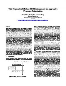
(a) Preference inconsistency
P2,1>P2,2 (Idle) c1 P2,1(Idle) =P2,2 (Idle) P2,1>Pc2 2,2 c1 γ1>-108dBm c2 γ1> γ2 +3dBm γ1>-108dBm
c2 c1
c1
c2
(Active) γ2>-106dBm
(Active) Load balancing
(Idle) P2,1=P2,2 γ1> γ2 +3dBm
(Active) γ1>-106dBm
(Idle) P2,1=P2,2 γ1> γ2 +3dBm
c1
c1
c2
(b) Threshold inconsistency (c) Active-idle misconfigura- (d) Active-state logic conflict tion
(Active) γ1>-106dBm
(Active) (Active) γ1>-106dBm c2 They are illustrated γin Figures 3a-3c. 1>-106dBm c1
c1
c1
c2
(e) Active-idle logic conflict
We first derive the conditions for parameters and runtime observations that would (not) trigger instability. Our analysis aims to answer two questions: (1) Under (Active) configurations, there exists (Active) which(Active) parameter some runtime obser(Active) Load balancing γ1-111dBm Load balancing γ -111dBm vations that can trigger instability? (2) Given improper parameter (Idle) P =Pwill 2,1=P 2,2 P2,1=PP configurations, which runtime observation values eventually 2,1 2,2 c1 (Idle) (Idle) (Idle) P =P c2 c1 2,2 c2 2,1 2,2 c2 c1 c2 γ+3dBm 1> γ2 +3dBm γ1> γ2instability? 1> γ2 +3dBm γ1> γ2 γ+3dBm trigger Then we conduct empirical assessments to validate their instances in operational 3G/4G networks.
5.1
Inconsistent Preference Values
In this category, each cell locally configures its preference, but these preferences are not globally coordinated. Figure 3a illustrates a simple two-cell case. In this setting, c1 configures c2 to be more preferred to c1 itself, but c2 assigns equal preference to both cells. The persistent loop happens if the signal strength satisfies γ2 > high Θhigh 2,1 (−108dBm), and γ1 > γ2 + Θ2,1 (3dBm). Note that, this loop can occur for any threshold settings (in the achievable range).
5.1.1
γ1-111dBm
Load balancing c2
Deriving Instability Conditions
We first derive the instability conditions for this category. Recall that, in the idle-state handoff (Figure 2), when associated with cell s, the mobile device evaluates each candidate c with the preconfigured preference Ps,c , and its runtime signal strength γc . Each cell c is compared with serving cell s, and would be selected if (1) it is more preferred than the serving cell, and its signal strength is higher than a threshold ((γc > Θhigh s,c )); (2) it is equally preferred, and its signal strength is offset higher than the serving cell’s (γc > γs + Θeqn s,c ), or (3) it is less preferred, but the serving cell’s strength is weak (γs < Θserv ), and the target cell’s signal strength s is satisfying (γc > Θlow s,c ). If more than one cell satisfies above condition, the one with highest preference could be chosen. The following result shows that, persistent loop can be caused by improper configurations of preference values. The good news is that, such persistent loops can be eliminated, when the derived preference conditions are avoided (the proof is in Appendix A): Proposition 1. Consider n cells c1 , c2 , ..., cn that use idle-state handoffs only. A loop c1 → c2 → ... → cn → c1 can always happen, if and only if their preference settings satisfy: (1) at least one cell ci sets Pi,i < Pi,i+1 , and (2) every cell cj sets Pj,j ≤ Pj,j+1 , and Pn,n ≤ Pn,1 . 2 Two results follow from Proposition 1. First, some preference settings would always trigger persistent loops with some runtime observations. For stability, they should always be avoided. Sec-
c1
(Idle) P2,1=P2,2 c2 γ1> γwith ond, consistent 2 +3dBm
c1
(Idle) P2,1=P2,2
c2
preference configuration, γ1> γ2 +3dBmthe idle-state decision logic can always ensure stability for a device. This serves as the foundation for stability analysis on other forms of handoff logic. As we will see in §5.2, there exists pairwise coordination methods for loop freedom. Enumerating all possible loops is not needed.
5.1.2
c2
γ1-106dBm γ2>-106dBm
(Idle γ1>-
c1
(Active) γ2>-106dBm
(Active) γ1-111dBm c2
(Idle γ1 γ2 + Θeq 2,1 (3dBm)). Therefore, the loop exists as long as the received signal strength meets the above condition. Similar misconfigurations can also occur in active-state handoff.
5.2.1
Instability Condition
We next derive the instability condition with respect to the radio threshold. We assume the preference settings are globally consistent, i.e. they all see the non-conflicting ordering on cell preference values. The following result shows the necessary and sufficient threshold configurations for any loop-free handoff (the proof is in Appendix B): Proposition 2. Consider n cells that use the idle-state handoffs only, and configure consistent preferences. The handoff stability is guaranteed iff. the radio thresholds are coordinated as follows: for every two cells ci and cj , (1)minci →ck Θhigh ≥ i,k high serv 2 serv Θj if Pi > Pj ; (2) mincj →ck Θj,k ≥ Θi if Pi < Pj ; eq (3) Θeq 2 i,j + Θj,i ≥ 0 if Pi = Pj .
Compared with Proposition 1, Proposition 2 offers a pairwise configuration between any two cells. With consistent parameter configurations, two-cell loop avoidance also implies larger loop avoidance. We further show that instability detection is still polynomial even with inconsistent preference (the proof is in Appendix C):
cell core 93
4000 2000
1226 6329 75
58
0 4G 3G Femto (a) Signaling overhead
100 80 60 40 20 00
Loop
Loop 4G 3G Femto 20 40 60 Load time (s) (b) Web browsing
100 80 60 40 20 00
CDF (%)
6000
CDF (%)
message #/ hour
8000
80
Loop 4G 3G Femto 50 100 150 Load time (s) (c) Music downloading and playing
Figure 6: Impacts of loops of L1.
Proposition 3. Given n cells at a location, the complexity of finding persistent loops is O(mn), where m is the number of idle-state handoff rules from all cells. 2
5.2.2
Empirical Assessment
For this category of idle-state threshold misconfigurations, our experiments report no conflicts in US-I/US-II. The traces show that, both carriers impose stricter conditions over the idle-state thresholds than required (by Proposition 2). The real threshold settings are fully decoupled from the preferences: no matter how preferences are configured, the high-preference threshold Θhigh (US-I: [-114dBm, -110dBm], US-II: [-114dBm, -111dBm]) is always higher than the serving threshold Θserv (US-I/II: [-120dBm,116dBm]) between any two cells. This signifies prudent engineering practice, contributing to good operations by both carriers in reality most of the time.
5.3
Active-Idle Misconfiguration
Instability may also be observed when the idle-state handoff is used in some cells but the active-state handoff is adopted in others. For instance, this could occur when the device exchanges highly bursty traffic, e.g., during Web browsing or instant messaging. The device thus stays active with traffic for a while, but then remains idle without traffic. This active/idle state switching is driven by the setup/release of radio connections, and is regulated by the Radio Resource Control (RRC) protocol [6]. For this scenario, uncoordinated configurations between idle and active state handoff may incur instability. Figure 3c illustrates such an example of two-cell loop. In the setting, c1 ’s active-state handoff policy evaluates c1 and c2 ’s signal strength with two thresholds. But it does not coordinate with c2 ’s idle-state handoff. So the persistent loops between them can happen when -111dBm< γ2 < γ1 − 3dBm Θi,j (b) indirect relative comparison: γi < Θ1i , γj > Θ2i,j ; (c) direct relative comparison: γj > γj + Θi,j . In §5.3.2, we will validate that this assumption holds in real operational networks. The following configurations ensure stability for active-idle misconfiguration (the proof is in Appendix D): Proposition 4. Consider n cells c1 , c2 , ..., cn that satisfy Assumption 1. The stability is guaranteed, if all cells’ active and idle-state handoffs’ radio thresholds are coordinated as follows. For every two cells ci and cj , consider ci ’s idle-state and cj ’s ≥ Θ1j if Pi > Pj active-state parameters: (1)minci →ck Θhigh i,k and cj uses absolute comparison; (2) mincj →ck Θj,k ≥ Θserv i if Pi < Pj and cj uses indirect relative comparison; (3) eq Θi,j + Θj,i ≥ 0 if Pi = Pj and cj uses direct relative comparison. 2
Given Assumption 1, any active-state handoff can be split into two parts: an equivalent “idle-state handoff” and decisions over other observations. Indeed, when only active-state handoffs are used, Proposition 4 is sufficient but not always necessary. Stability can be ensured through other means (e.g. coordinating other parameters). The merit of Proposition 4 stems from its support for idle-state handoffs: it ensures stability within active-state handoffs only, and between idle and active state handoffs.
5.3.2
Empirical Validation
Validation of Assumption 1. We first exam whether Assumption 1 holds in real mobile networks. Constrained by no access to the operator’s internal handoff decision logics, we gauge it from the runtime cellular messages exchanged between the device and the network (the serving cell). This is viable because in 3G/4G active-state handoff decision is device-assisted: the mobile device reports the radio measurement results to the serving cell, and then the serving cell makes the decision. We find that, both US-I and US-II’s active-state handoff commands are usually directly triggered by 3G/4G RRC radio measurement reports, whose triggering conditions are standardized in [3, 6] and satisfy Assumption 13 . So effectively, the serving base station’s handoff logic evaluates radio quality that satisfies Assumption 1. To demonstrate this, we calculate (1) the probability that the active-state handoff occurs after the measurement report, and (2) the device-perceived time interval between the delivery of last measurement reports and receipt of the active-state handoff command. Higher occurrence probability and smaller time interval would imply closer relation between activestate handoff and RRC measurement reports. 3
For example, in 4G RRC, the report criteria A4 and B1 are the absolute comparisons, criteria A5 and B2 are the indirect relative comparisons, and criteria A3 is the direct relative comparison.
#. Active-state handoff Occurrence probability after RRC measurement report Interval between handoff command and last RRC measurement report
Total Absolute comparison Indirect relative comparison Direct relative comparison Min Med Max
US-I 11,050 99.7% 1.0% 21.2% 77.5% 40.6ms 79.9ms 141.4ms
US-II 10,178 97.8% 3.2% 34.2% 60.4% 20.1ms 60.0ms 266.5ms
Table 3: Probability and the elapsed time of active-state handoff which is triggered by RRC measurement report [3, 6] (satisfying Assumption 1).
Table 3 shows both results. For both US-I and US-II, 99.7% and 97.8% active-state handoff happens after device sends RRC measurement reports, respectively. Among these handoff commands, 77.5% (60.4%) are initiated after RRC measurements triggered by direct relative comparison (e.g., event A3 in 4G RRC). The time interval between the last measurement report (from device) and the handoff commands are short: the medium value is 79.9ms (60.0ms), while the maximum value is 141.4ms (266.5ms) in US-I (US-II). Both imply that, on reception of device’s radio measurement reports (satisfying Assumption 1), the serving base station’s decision logic immediately determines to trigger active-state handoff. This is coherent with the public literature [2, 6, 7, 24, 27]. Validation of active-idle misconfiguration. In this subcategory, our detection tool has found one instance in US-I (L4). We observe threshold incoordination between 3G Macrocell’s idle-state handoff and Femtocell’s active-state handoff for voice. The scenario is similar to that of Figure 3c. The device oscillates between 3G Macrocell (c1 ) and Femtocell (c2 ) when γ1 < −102dBm, γ2 > −111dBm, γ1 > γ2 + 3dBm. Interestingly, though no threshold misconfiguration is observed at the idle state, it occurs between idle and active-state handoffs. This threshold incoordination is not shown without reasons. The Femtocell tends to move the active-state user to the Macrocell, even when the Macrocell’s signal strength is weaker than the Femtocell’s. This is because the Femtocell is deployed by users in an unplanned and isolated fashion. Its radio coverage is smaller than that of the Macrocell’s. So the device has a higher chance to leave the Femtocell coverage. To avoid the potential voice call disruption, the Femtocell proactively switches the device to the Macrocell earlier than needed. Unfortunately, this configuration violates Proposition 4, and fails to achieve the expected goal. The device may handoff back to the Femtocell at the idle state under the same observations. We test this loop at all viable indoor locations. At each spot, we launch a 24-hour test, and periodically load the webpage with Firefox every five minutes. We count the total number of connections, and how many experience the looped transition between two cells. The active-state handoff condition is satisfied with probability 9.4% (see Table 4). However, once satisfied, the loop always occurs in our test. We run the same webpage loading test to assess its impact on user traffic. As shown in Figure 7, this loop incurs extra delay about 40–90 seconds.
6.
INSTABILITY BY LOOP-PRONE DECISION LOGIC
In this major class of instability, persistent loops may occur if cells apply conflicting handoff decision logics. Different from uncoordinated parameters, no matter how well parameters are tuned, conflicts always exist between decision engines. The fundamental root cause is that, the active-state handoff logic is customizable
at each cell. We further discover two categories of instability in this class, one is between active-state logic (§6.1), and the other between active and idle-state engines (§6.2).
6.1
Active-Active Logic Conflicts
The category of instability may appear due to loop-prone decision logic, despite identical parameters. The root cause is that, active-state handoff may use decision logic different from the common one defined by its idle-state counterpart. Operators may customize the logic. Figure 3d illustrates a two-cell-loop example. The active-state handoff decision logic at each cell adopts a simple rule: both agree to switch to the other if the signal strength at the neighboring cell is good enough (e.g. >-106dBm). However, if both cells satisfy the signal strength condition, the loop would occur. Note that regardless of the radio threshold to be set, the signal strength that satisfies the loop condition always exists.
6.1.1
Analytical Result
We now derive the stability conditions for the active-state decision logic. When all active-state decision engines assess radio quality and satisfy Assumption 1, loop-prone logic can be eliminated as follows (the proof is similar to Appendix D): Proposition 5. Consider n cells c1 , c2 , ..., cn that satisfy Assumption 1. The stability is guaranteed, if all cells’ active and idle-state handoffs’ radio thresholds are coordinated as follows. For every two cells ci and cj , consider ci ’s idle-state and cj ’s active-state parameters: (1)minci →ck Θi,k ≥ Θ1j if ci uses indirect relative comparison, and cj uses absolute comparison; (2) mincj →ck Θj,k ≥ Θ1i if ci uses absolute comparison, and cj uses indirect relative comparison; (3) Θi,j + Θj,i ≥ 0 if ci and cj use direct relative comparison. 2
Proposition 5 specifies a sufficient condition for loop-free, active handoffs. It is applicable to any handoff decision logic among cells, as long as it assesses radio quality. By coordinating the radio evaluation portion, no observations on the radio quality can lead to a loop. There are two benefits to this approach. First, it does not require coordination of other unknown parameters, thus being flexible and extensible. Second, it is also backward compatible with the idle-state handoff. This helps to prevent persistent loops between active-state handoffs, and between active and idle-state handoffs.
6.1.2
Empirical Validation
Our tool also detects one instance (L5) between two 4G cells in US-I at one location (Figure 3d). Both cells try to offload users to each other, when the other’s signal strength is higher than certain threshold. However, such load-balancing decisions are not coordinated. A user thus oscillates between these two cells. Fortunately, this loop is not commonly observed. Among all 4G cells we collect, 67% of them use the same policy for the active-state handoff, but its neighboring cells are not observed to use the same rule except at one location. At this location, we conduct 6-hour ping tests and observe 8 loops (every 45 minutes on average) and the minimum one lasts only 43 seconds. We further discover that, active-state loop-prone handoff engines are less observed due to prudent engineering practice. In US-I/USII, most Macrocells’ active-state decision logic is more conservative than their idle-state handoffs’ counterpart. The radio quality measurements, which may trigger idle-state handoffs, cannot always trigger active-state handoffs in the same cell. The RRC measurement configuration for active handoffs uses stricter thresholds and report criteria than their idle-state handoff counterpart. The
6.2
Active-Idle Logic Conflicts
This category of instability occurs when some cells apply idlestate handoffs, while others use active-state handoffs. Instability is always triggered if the handoff does not assess radio quality. This can be illustrated by the example of Figure 3e. In this case, c1 ’s active-state decision never considers the signal strength used by the c2 ’s idle-state handoff. Instead, c1 uses load-balancing, regardless of the radio quality. Consequently, the serving cell oscillates between c1 and c2 once the switch conditions are satisfied in both handoff iterations. It shows that incoordination between decision logic functions is responsible for this unnecessary loop.
6.2.1
Analytical Result
If the active-state handoff does not assess radio quality, we show that idle-active loops would always occur: Proposition 6. Two-cell persistent loop between ci and cj always exists, if ci ’s active-state logic to cj does not evaluate radio quality, while cj applies idle-state decision logic to ci . 2 The proof can be found in Appendix E. In practice, the idle-state decision logic is available at all devices. Proposition 6 implies that, if a cell ci ’s active-state handoff logic does not assess radio quality, the only possibility to avoid loops is that all its neighboring cells do not allow handoffs to ci . However, this cell would consequently become isolated from others.
6.2.2
Empirical Validation
We have found two instances in this category, one (L6) in US-I and US-II, and the other (L7) in US-I only. L6 happens between two 3G Macrocells, whereas L7 happens between a 3G Macrocell and a Femtocell. The handoff decision logic is shown in Figure 3e, with c1 = 3G and c2 = 3G/Femtocell. This setting violates Proposition 4. Our study shows that, both instances are caused by a design defect in 3G Radio Resource Control (RRC) protocol. The 3G RRC defines an offloading mechanism during connection setup. When a device attempts to setup a radio connection, the cell can reject the device’s request, and redirects the device to a nearby cell [3]. However, this redirection cannot take cells’ radio quality into consideration. Without a connection, the device cannot report the observations to the cell. If the current cell’s radio quality is better
Load Time (s)
reason is that, active-state handoff is usually activated with data traffic. It tends to be more conservative to ensure the seamless data/voice service. Since the idle-state handoffs’ thresholds follow the conservative loop-free setting, it is not surprising to see fewer active-state-only handoff loops. Another related finding is that, the active-state loop-prone handoff logics are more common in 4G. In both US-I and US-II’s 3G Macrocells, we didn’t observe loop-prone handoff logics in active state. Our experiments show that, both operators’ 3G activestate handoff logics are even more conservative than 4G’s activestate counterparts: only handoffs between cells under the same frequency (intra-frequency handoff) are used, whose triggering condition is based on the direct relative comparison between serving and neighboring cells’ radio qualities (Assumption 1). The reason is that, different from 4G LTE, 3G UMTS supports soft handover between cells under the same frequency. Because of this, intrafrequency handoff offers more seamless data service in mobility, thus more preferred by network operators. This further limits the available candidate cells, thus less prone to loops than 4G.
120 100 80 60 40 20 0
3G
Femto
L4
L6
L7
Figure 7: Impacts of loops of active-idle misconfiguration logic conflicts (web page loading). than neighbors’, the offloading cannot succeed, because the device would shift back in idle state. We quantity both loops’ impact under similar experiment settings to those for IS1-C3. We find that L6 and L7 are not commonly observed even when the loop condition is satisfied. L6 and L7 occur at the probability of 2.15% and 0.49% in our observation at one location (Table 4). The serving-cell congestion probability largely decides the loop occurrence. As shown in Figure 7, both loops incur delay about 20–53 seconds (median), up to two minutes. We observe that some phones do not always follow the cell’s handoff command. Instead, they seek to reconnect to the serving cell. This is why the user device may still not suffer from it even when the loop condition is met.
7.
AUTOMATIC LOOP DETECTION
With above analytical findings, we next design and implement a software tool, which enables automatic detection on handoff instability. Given the parameters and decision logics from cells at a location, our tool reports the conflicting parameters/logics that may incur instability, uncovers their root causes, and identifies the possible runtime observations that will trigger the loop occurrence.
7.1
Design
At first glance, loop detection looks fairly simple. A straightforward straw man solution works as follows. Given handoff configurations from all cells, the tool first enumerates all the looped handoff transitions c1 → c2 → ... → cn → c1 . For each of them, a persistent loop would be reported, if there exist some runtime observations that can satisfy handoff configurations concurrently. To uncover root causes, we search whether there exists a set of configurations for each handoff that can eliminate the loop. If yes, then the loop is incurred by uncoordinated configurations (§5); otherwise, it is due to loop-prone logic (§6). However, this approach is deemed impractical. Enumerating loops implies state explosions on the number of cells and configurations. Uncovering root causes further incurs exponential search over the configuration space. To address both issues, we apply the domain-specific (in)stability conditions to reduce the complexity. We differentiate loops with/without active-state handoffs, and apply distinctive techniques for loop detection and cause inference. ◦ Idle-state handoff only. We adopt a two-step procedure to detect all idle-state handoff loops. First, given all cells at each location, we check if these cells’ preference settings are consistent. If so, enumeration can be replaced with pairwise threshold check according to Proposition 2. Otherwise, enumeration with pruning is applied based on Proposition 1. In each round, we seek to find all loops with a cell ci involved. Starting from ci , we run a variant DFS algorithm over the graphs of handoff transitions. For each cell cj to be visited, a variable γj is maintained, which denotes the potential radio measurement violating stability. We initialize γi , and derive γj recursively. When cj is visited from ck , (1) if Pk,j > Pk,k , then
Output: loop counterexamples Policy Conflict Detection Handoff Policy Abstraction Idle-state Handoff Database
Active-state Handoff Inference
Input: Signaling Messages
Figure 8: In-device for loop detection. eq γj ← Θhigh k,j ; (2) if Pk,j = Pk,k , then γj ← γk + Θk,j ; (3) if serv Pk,j < Pk,k , cj is pruned if γk > Θk ; otherwise, γj ← Θlow k,j . If ci is visited again, a loop is reported if γi can satisfy the last handoff transition. Once all loops with ci are found, we remove ci from the cell list, and detect loops for the remaining cells. The root cause analysis is straightforward, since the loops in this category can only be caused by misconfigurations. ◦ Active and idle-state handoff. With active-state handoffs, we apply Propositions 4, 5 and 6 to eliminate unnecessary enumerations. For each cell c, we first check if its active-state handoff execution evaluates radio quality. If not, idle-active handoff loops are reported between c and its neighbors, with the cause “loopprone logic” (Proposition 6). We further remove c, and replace each handoff transition from c with a new one from c’s parents, with the configuration as that for parent(c) → c. Next, if all cells’ handoff executions apply pairwise radio quality evaluation, we check if they satisfy Propositions 4 and 5. If yes, no loops would be reported. This helps to avoid checking other parameters. Otherwise, enumeration would be invoked in the worst case.
7.2
In-phone Implementation
Since we have no access to the cellular network infrastructure, we implement the above design in the mobile device. Figure 8 illustrates our implementation. We first enable in-device cellular configuration collection with MobileInsight [1], a system app to collect signaling messages. With these inputs, our tool actively synthesizes the abstract model and applies the loop detection algorithm. ◦ Handoff configuration collection. Our implementation proactively switches the phone to every cell at each location (via e.g. secret code *#2263# in Samsung S5), and collects both idle and active-state handoff configurations. The idle-state handoff configurations can be readily derived from the standardized logic and parameters from the System Information Block (SIB) messages. The active-state handoff ones are not visible to the device. To infer them, we observe that the serving cells’ measurement configurations are available, which are designed for active-state handoffs. These report criteria are standardized in [3, 6] and satisfy Assumption 1. For each cell, our implementation monitors these configurations and handoff commands in RRCReconfiguration message, together with the measurements from the device. If a handoff command without measurement is observed, a configuration without radio evaluation is inferred. Otherwise, all measurement reports before the command are treated as potential configurations, and checked in the loop detection. ◦ Parameter abstraction. The actual configurations should be mapped to the abstract parameters before detection. Following [3, 6], we perform three parameter conversions before the detection: (1) threshold set selection, in which we select the corresponding thresholds based on the usage scenarios (e.g. RSRP or RSRQ as the
radio metric, normal or VoLTE active-state handoff); (2) threshold combination, in which we combine different offsets/hysteresis from real parameters to the thresholds in the model. For example, in the equal-preference, idle-state handoff, the threshold Θeq s,c in the model is the sum of the serving cell’s hysteresis, the frequencyspecific offset, and the cell-specific offset; (3) threshold scaling, in which we scale the thresholds based on the speed-scaling factors from SIBs. ◦ Loop detection. We implement the detector in Python, which accepts the abstract model as input, and reports the counterexamples. Each report includes the cells in the loop, the conflicting configurations, and the measurements that can trigger the loop. They are used to set up the validation experiments in Sections 5 and 6. Accuracy analysis. For idle-state handoff only, our tool guarantees that it can find all loops without false positives/negatives. This is because that the phone has full knowledge of the idle-state handoffs, including its decision logics (standardized) and parameters (from the signaling messages). For active-state and active-idle loops, false positive exists. This is because our inference of the decision logics based on Assumption 1 may be incomplete. So the over-detection may exist: active-state and active-idle loops reported by our tool may not always happen in reality. But false negative is still prevented from active-state and active-idle loops: if a loop exists, it would always be detected by our tool. Limitations. Our current design and implementation have three downsides. First, the loops reported in our design may not always be observed in practice, because the observations triggering the loops may not always appear. To test the loop existence, validation experiments should be conducted. However, they still offer hints for validations, and should be fixed because external measurements cannot always be controlled to avoid loops. Second, the active-state handoff configurations are not accessible to device-side implementation. This causes false positives, and prevents us from uncovering more insights on the active-state handoff. Third, without access to the carrier’s handoff configurations, our tool has to be run area-by-area to detect the loops.
7.3
Experiments on Operational Networks
We run the designed tool to validate persistent loops from real carrier configurations, and quantify their negative impacts. Figure 9 summarizes the outdoor and indoor test settings. The cell distribution at different outdoor locations confirms that today’s deployment is quite dense and hybrid. At most locations, there are about 8–16 cells. On average, there are about 11 cells in US-I and 10 cells in US-II. The number of unique cells, excluding those observed at multiple locations, are 275 (4G: 120, 3G: 97, 2G: 58) in US-I and 222 (4G: 92, 3G: 66, 2G: 64) in US-II. It confirms that 4G cells have smaller coverage and denser deployment whereas the 2G coverage is much larger. The indoor setting has similar cell density as the outdoor one. Figure 9c plots the median radio signal strength measured at 50 indoor spots in US-I networks. For 2G/3G/4G comparisons, we use normalized percentages obtained from OpenSignal4 , a popular network monitor app, where 0% indicates no coverage and 100% indicates strongest signal strength5 . It implies that despite higher speed, 4G suffers worse coverage than 3G and 2G in indoor scenarios. The results in US-II are similar and thus omitted here. We also validate that, the assumption of invariant runtime ob4
http://opensignal.com/android/ 4G uses different signal strength metrics from 3G/2G. The minimal strength observed in 3G/2G is -113dBm whereas it is around -125dBm in 4G. 5
4G 3G 2G Total 0 5 10 15 20 (b) Outdoor cell density in US-I
25
Signal strength (%)
100 80 60 40 20 0
CDF (%)
Avg. cell#/spot Unique cell# US-I US-II US-I US-II #4G 2.6 2.1 120 92 #3G 3.4 2.4 97 66 #2G 5.4 5.6 58 64 #All 11.4 10.1 275 222 (a) Statistics of outdoor cell deployment
100 50
4G
3G
2G
0 50 0 50
0 10 20 30 40 50 (c) Indoor radio signal strength at 50 spots in US-I
Figure 9: Summary of outdoor and indoor deployment. #Scenario instances L1: L2: L3: L4: L5: L6: L7:
4G-Femto-3G 4G-Femto-2G-3G 4G-4G 3G-Femto 4G-4G 3G-3G 3G-Femto
8 8 1 1 1 1 1
Occurrence of Misconfigurations or Loop-prone logic 96.8% 96.8% 2.2% 96.8% 1.6% 63.4% 96.8%
Loop occurrence (parameter+logic +observation) 25.0% 0.49% 2.2% 9.4% 1.6% 2.15% 0.49%
Table 4: Loop occurrence probability in US-I.
servations in persistent loop is reasonable in practice: in response to runtime radio measurement, both US-I and US-II’s handoff decision-makings takes no more than 141.4ms and 266.5ms (§3), respectively. For comparison, for all the tested indoor spots, 95% of cells’ signal strength change at same spot takes more than 229.5ms (5.10s) in US-I (US-II), which is much slower than handoff decision making. So during the handoff decision, it is safe to make the invariant runtime observation assumption. The detailed findings on each category have been described in Sections 5 and 6. With our tool, we have found 21 instances of potential misconfigurations and/or loop-prone logics, which are further classified into 7 categories. For each category, we further run indoor experiments to validate its existence, and estimate its occurrence probability. For each indoor spot, we run a 24-hour test and record the looped handoffs between cells. Table 4 lists the occurrence probability of problematic configurations (left column), and the occurrence probability of loops (right column) observed at one specific location. Other locations have similar results. It shows that, instabilities occur in 2G, 3G and 4G networks, with varying occurrence probabilities. From these instances, we show that, loops with both the uncoordinated configurations and loop-prone decision logic indeed exist. Although carriers have applied at least two prudent rules to mitigate loops, configuration conflicts still exist for various reasons, such as diverse handoff goals, the incremental and/or unplanned cell deployment, the device misconfiguration, and the design defects for the connection control mechanism. Loops incur negative impacts upon both the user and the network. We notice a big distinction between both columns, which reflect the gaps of the root causes and the actual impact. The reason is that, the occurrence of actual loops (right column) is also affected by another runtime observations, which may not always be satisfied. It has two implications. First, misconfigurations or loop-prone logics that may trigger persistent loops are not rare in reality. Most settings are problematic once femtocells are deployed. It indicates that the operator’s network infrastructure is not fully upgraded to handle small cells which can be deployed by users. Second, although the misconfigurations occur with high probability, the satisfying signal strength that triggers loops do not always occur. For example, only L1 (25%) is relatively common and other loops like L2, L3, L5, L6 and L7 are rarely observed (below 2%). This is attributed to good practice and satisfactory coverage in radio planning and cell deployment.
8.
DISCUSSIONS
We now discuss how to fix the configuration conflicts and their resulting loops. Given that persistent loops hurt both the user performance and the network’s operation, we envision that both carriers and users have incentives to remove loops. We next propose solutions to both sides.
8.1
Network-Side Coordination
The carrier should coordinate cells’ local configurations to avoid handoff instability. There are two issues to be addressed: (1) How to resolve loops from the existing handoff configurations, and (2) How to avoid new persistent loops from configuration updates? Fixing existing loops. The carrier can take two steps. First, the operator should check if configuration conflicts exist at each location. This can be done with our loop detection tool (§7). In the second step, conflicting configurations in loop may be coordinated for stability. It should be noted that, there can be more than one way to fix each loop. Consider the actual loop with the Femtocell involved in Figure 4 (§5.1.2). At least two fixes are available: (i) on 4G Macrocell, assign lower preference to Femtocell, or (ii) on Femtocell, assign lower preference to 3G Macrocell. The carrier may pick either one based on its demand. For example, applying (i) can provide users with high-speed data service in 4G, while choosing (ii) enables traffic offloading from 4G to 3G. However, not all schemes are bullet-proof. New loops may appear when fixing old ones. For example, the following scheme can also fix the above loop: (iii) on Femtocell, assign higher preference to 3G Macrocell. However, this causes a new loop F emtocell → 3GM acrocell → F emtocell, because it violates Proposition 1. To address this, one could detect the loop again after the fix, and resolve new loops. But this requires enumeration of all configurations. More importantly, there is no guarantee that all loops will be finally fixed. We propose a general guideline to determine a safe loop fix. Assume a fix requires to modify the configuration for ci → cj . Our guideline imposes a monotonic condition over this fix: Guideline 1. (Safe configuration update) For any runtime measurements that cannot trigger ci → cj before the configuration update, it should not trigger ci → cj after the update. If Guideline 1 is followed, it is straightforward to prove that, for any loop that exists after this configuration update, it must have already existed before the update. New loops cannot appear thereafter. No extra actions are needed after the old loop fix. So if all fixes obey this rule, all loops will be ultimately fixed. Handling policy update. The handoff configurations or decision logics can change over time for various reasons, including incremental/unplanned cell deployment, tuning some cells’ handoff goals, etc. The carrier may expect to retain stability after the update. We discuss how to achieve this in a single configuration update ci → cj , assuming that stability is guaranteed before the change. Stability with multiple updates can be ensured with each step satisfying the following criteria.
Consider cell ci adds a new handoff rule to cj . Two approaches exist to prevent new loops. The first one is to detect loops after the addition, which however implies enumeration of loops (§7). The second is to apply constraints over the new update, without coordinating with others. In §5-6, we have seen two prudent rules from real carriers: (1) for a new idle-state handoff, set threshold Θhigh higher than threshold Θserv , regardless of the preference setting; (2) for a new active-state handoff, set it as at least conservative as the corresponding idle-state handoff. Both rules help to avoid new loops. Propositions 1– 6 also impose such conditions on new updates. Next consider a configuration deletion: a cell ci deletes its local handoff toward cj . The stability is still retained, because no new handoff transitions are introduced. The last scenario is to modify an existing handoff configuration for ci → cj . This update is equivalent to a two-step procedure: delete the old configuration, and then add the new one. The first step does not cause new loops, while the second step can be safeguarded by above rules for new configurations. Guideline 1 is also applicable here: If the new policy is as conservative as the old one, the overall mobility are still stable after the update. Runtime mitigation? In addition to configuration coordinations, we are aware that loops can be mitigated at runtime, similar to the transition loops due to radio dynamics. The mobility history can be used to stop the loops by blocking visited cells [9]. Signaling reduction techniques can reduce the impacts [4]. Despite helpful, they do not offer fundamental fixes to loops. Since the configuration-based loops are fixable, the carrier should not rely on runtime mitigations only. Instead, they should fix the configuration conflicts. Implementation suggestions. To fix existing loops, a centralized controller is needed for configuration coordination. For loops between cells from the same area, loop resolution can be implemented at the location area controller. For other loops, higher-layer controller may be needed. For configuration updates, they can be handled in either centralized or distributed fashions. If loop detection is used, a central controller is still needed. If extra constraints are applied to configuration addition/modification, the resolution can be implemented at each cell. Every cell discovers all neighboring cells’ handoff configurations under the self-organizing network (SoN) framework [7, 8], and apply these constraints over its own updates.
8.2
Device-Side Loop Prevention
When loops are not fixed by the carrier, the mobile device has the incentive to prevent itself from suffering from loops. Although the device cannot coordinate configurations among cells, it can configure itself to eliminate loops. At each location, the device can actively collect all cells’ configurations, and run the loop detection algorithm (§7). Upon detecting a loop, the device can either statically block some cells, or stop the handoff procedure at runtime. Noted that, this device-side approach cannot replace the network-side configuration coordination. Without the network-side fix, users without this scheme still suffer from persistent loops.
9.
RELATED WORK
In recent years, there have been extensive research efforts on 3G/4G mobile networks. They include radio analysis [11,21], TCP over cellular network [18, 29], cross-layer optimization [13, 19], and software-defined cellular networks [17, 20]. On mobility support, extensive optimizations have been proposed for diverse goals, including reducing radio link failure and transient oscilla-
tions [14, 24], traffic offloading [12, 16], and supporting heterogeneous network [15, 23]. Instead of optimizing one specific handoff goal, our work focuses on the conflicts between handoff policies (with possibly different goals). Our preliminary work [22] discloses the existence of persistent loops in idle-state handoffs and this work greatly extends it. We conduct a systematic study with both analysis and empirical validation and covers both idle-state handoffs and active-state handoffs. Misconfigurations and management-plane conflicts have been examined in other Internet systems such as BGP [25], DNS [26], and data center networks [28]. Our work is inspired by such early efforts, but focuses on the management plane for mobility management in 3G/4G mobile networks. We show that policy-driven configurations may lead to instability during handoffs.
10.
CONCLUSION
Mobility support is a key utility function offered by 3G/4G cellular networks. As more mobile users are accessing the Internet from their smartphones through the 3G/4G infrastructure, mobility management is likely to become more critical. Like all operational networks, current mobile carriers allow for flexible configurations on their micro-mobility support scheme to address policy concerns. This management-plane aspect on mobility has been largely overlooked by past research efforts. In this work, we seek to conduct a first study toward this general direction. Our results can be best interpreted from both viewpoints. On one hand, our effort yields some interesting and new findings. The discovered persistent loops, as well as their triggering conditions, have been partially validated in operational networks. Though the incurred damage, in terms of signaling overhead and performance degradation, is not appalling to some users, such problematic issues should be addressed as we seek to build a more dependable, highperformance, mobile network infrastructure. The presented analysis, as well as modeling, despite a little simplistic, also produces some interesting results not reported in the literature. On the other hand, this work is still at the early stage, and the obtained results are likely to be refined over time. Several important issues (e.g., other configuration parameters, and more forms of customized decision logic) have been overlooked so far. Moreover, other structural properties (e.g., whether the handoff process converges to the anticipated cell, and the convergence speed) warrant further efforts. In the broader context, moving beyond current focus on both data and control planes, management plane in 3G/4G mobile networks (hopefully also the upcoming 5G) is still a wide-open research area and deserves more attention. We hope our effort may stimulate more people in the community to work on this important direction. Acknowledgments: We thank the anonymous reviewers for their constructive comments. We greatly appreciate our shepherd, Dr. Bozidar Radunovic for his valuable feedback. We also thank Jie Zhao for participating in trace collection in this work. This work is supported in part by NSF awards (CNS-1526456, CNS-1526985, CNS-1423576 and CNS-1421440).
11.
REFERENCES
[1] Mobileinsight project. http://metro.cs.ucla.edu/mobile_insight. [2] "ZTE UMTS Handover Description". http://www.slideshare.net/quyetnguyenhong/zteumtshandoverdescription. [3] 3GPP. TS25.331: Radio Resource Control (RRC), 2006. [4] 3GPP. TS24.008: Mobile Radio Interface Layer 3, 2012. [5] 3GPP. TS25.304: User Equipment (UE) Procedures in Idle Mode and Procedures for Cell Reselection in Connected Mode, 2012. [6] 3GPP. TS36.331: E-UTRA; Radio Resource Control (RRC), 2012.
[7] 3GPP. TS32.522: Self-Organizing Networks (SON) Policy Network Resource Model (NRM) Integration Reference Point (IRP), 2013. [8] 3GPP. TS32.511: Telecommunication Management; Automatic Neighbor Relation management; Concepts and Requirements, 2014. [9] 3GPP. TS36.413: S1 Application Protocol (S1AP), 2014. [10] 3GPP. TS36.304: E-UTRA; User Equipment Procedures in Idle Mode, 2015. [11] P. K. Athivarapu, R. Bhagwan, S. Guha, V. Navda, and et.al. Radiojockey: mining program execution to optimize cellular radio usage. In ACM MobiCom, Aug. 2012. [12] A. Balasubramanian, R. Mahajan, and A. Venkataramani. Augmenting mobile 3g using wifi. In ACM MobiSys, June 2010. [13] N. Balasubramanian, A. Balasubramanian, and A. Venkataramani. Energy consumption in mobile phones: A measurement study and implications for network applications. In IMC, 2009. [14] C. Brunner, A. Garavaglia, M. Mittal, M. Narang, and J. V. Bautista. Inter-system Handover Parameter Optimization. In VTC Fall, 2006. [15] M. Z. Chowdhury, W. Ryu, E. Rhee, and Y. M. Jang. Handover between Macrocell and Femtocell for UMTS Based Networks. In IEEE ICACT, 2009. [16] W. Dong, S. Rallapalli, R. Jana, L. Qiu, K. Ramakrishnan, L. Razoumov, Y. Zhang, and T. W. Cho. ideal: Incentivized dynamic cellular offloading via auctions. TON, 22(4):1271–1284, 2014. [17] A. Gudipati, D. Perry, L. E. Li, and S. Katti. Softran: Software defined radio access network. In Proceedings of the second ACM SIGCOMM workshop on Hot topics in software defined networking, pages 25–30. ACM, 2013. [18] J. Huang, F. Qian, Y. Guo, Y. Zhou, Q. Xu, Z. M. Mao, S. Sen, and O. Spatscheck. An in-depth study of LTE: Effect of network protocol and application behavior on performance. In SIGCOMM, 2013. [19] U. Javed, D. Han, R. Caceres, J. Pang, S. Seshan, and A. Varshavsky. Predicting handoffs in 3g networks. In MobiHeld, 2011. [20] X. Jin, L. E. Li, L. Vanbever, and J. Rexford. Softcell: scalable and flexible cellular core network architecture. In CoNEXT, 2013. [21] S. Kumar, E. Hamed, D. Katabi, and L. Erran Li. LTE Radio Analytics Made Easy and Accessible. In ACM SIGCOMM, 2014. [22] Y. Li, J. Xu, C. Peng, and S. Lu. A First Look at Unstable Mobility Management in Cellular Networks. In HotMobile, Feb 2016. [23] M. Liu, Z. Li, X. Guo, and E. Dutkiewicz. Performance Analysis and Optimization of Handoff Algorithms in Heterogeneous Wireless Networks. IEEE Transactions on Mobile Computing, 7(7):846–857, July 2008. [24] A. Lobinger, S. Stefanski, T. Jansen, and I. Balan. Coordinating Handover Parameter Optimization and Load Balancing in LTE Self-Optimizing Networks. In VTC Spring. IEEE, 2011. [25] R. Mahajan, D. Wetherall, and T. Anderson. Understanding BGP Misconfiguration. In ACM SIGCOMM CCR, 2002. [26] V. Pappas, Z. Xu, S. Lu, D. Massey, A. Terzis, and L. Zhang. Impact of Configuration Errors on DNS Robustness. In SIGCOMM, 2004. [27] G. P. Pollini. Trends in Handover Design. IEEE Communications Magazine, 34(3):82–90, 1996. [28] P. Sun, R. Mahajan, J. Rexford, L. Yuan, M. Zhang, and A. Arefin. A Network-State Management Service. In ACM SIGCOMM, 2014. [29] F. P. Tso, J. Teng, W. Jia, and D. Xuan. Mobility: A Double-Edged Sword for HSPA Networks: A Large-Scale Test on Hong Kong Mobile HSPA Networks. IEEE Transactions on Parallel and Distributed Systems, 23(10):1895–1907, 2012. [30] Wikipedia. Handover. http://en.wikipedia.org/wiki/Handover. [31] D. Wong and T. J. Lim. Soft handoffs in CDMA Mobile Systems. IEEE Personal Communications, 4(6):6–17, 1997.
APPENDIX A.
PROOF FOR PROPOSITION 1
The proof is based on the fact that, the above preference setting is non-decreasing. We can always find a runtime observation that high incurs loop as follows: (a) γi+1 > Θhigh i,i+1 , and (b) γj+1 > Θj,j+1 eq if Pj,j < Pj,j+1 , or γj+1 > γj + Θj,j+1 if Pj,j = Pj,j+1 . On
the other hand, if above preference setting does not hold, two cases may arise: (1) all cells are of equal preference, then Proposition 2 below will guarantee the loop freedom; (2) at least one cell ck has Pk,k > Pk,k+1 , then the loop can be avoided by setting Θserv k equal to the minimum achievable signal strength. 2
B.
PROOF FOR PROPOSITION 2
The proof starts from the two-cell case. By enumerating all potential looped transitions, we verify that two-cell loops can be eliminated if and only if the above condition holds. This way, the necessity of Proposition 2 is readily guaranteed. The sufficiency of the condition is further proven via contradiction. Assume the above threshold conditions are satisfied, but a larger loop c1 → c2 ... → cn → c1 still exists. There are two possibilities: (a) all cells are of equal preference. By listing their handoff decisions (inequalities) and summing them up, it can be readily shown that (3) is not satisfied; (b) some cells are of different preference. Then it can be shown that there always exists one cell applying highpreference decision, another cell applying low-preference decision, and any cells in between applying equal-preference decision. By listing their handoff decisions (Figure 2) and summing them up, it can be readily shown that (1)–(3) are not satisfied. 2
C.
PROOF FOR PROPOSITION 3
We prove it by constructing a corresponding algorithm. Given an arbitrary cell ci , we find all loops with ci involved. Starting from ci , we run a variant DFS algorithm by following the idle-state decision rules for transition. In the process, for each cell cj to be visited, a variable γi,j is maintained, which denotes the potential signal condition violating stability. When cj is visited by ck in DFS, (1) if Pk,j > Pk,k , then γi,j ← Θhigh k,j ; (2) if Pk,j = Pk,k , then γi,j ← γi,k + Θeq ; (3) if P < P k,j k,k , cj is pruned in DFS k,j low if γi,k > Θserv , otherwise γ ← Θ . Whenever ci is visited i,j k k,j again, a persistent loop is reported. Once all loops with ci involved are found, we remove ci and all the related decision rules from the cell list, and detect loops for the remaining cells. 2
D.
PROOF FOR PROPOSITION 4
We prove this with a concrete configuration scheme. For every active-state decision logic ci → cj , we define an auxiliary “idle-state” handoff logic based on its radio evaluation part. If form (a) in Assumption 1 is used, then the auxiliary logic is defined as Pi,j > Pi,i , Θhigh = Θi,j . If (b) is used, it is defined i,j low = Θ1 as Pi,j < Pi,i , Θserve i , Θi,j = Θ2i,j . Otherwise, it is i eq defined as Pi,j = Pi,i , Θi,j = Θi,j . This auxiliary logic has the following property: for any runtime observation that can trigger active-state handoff ci → cj , it can also trigger this idle-state handoff. Then we replace all active-state handoff policies with auxiliary ones, and apply Propositions 1 on all policies for threshold coordination. Based on the relation between active-state handoff and the auxiliary “idle-state” handoff, this coordination ensures stability among idle and active-sate handoff decisions. 2
E.
PROOF FOR PROPOSITION 5
It is proven by contradiction. Note that, regardless of the preference and/or threshold setting on cj , certain cell radio quality γi and γj can trigger idle-state handoff from cj to ci . Without evaluating radio quality, ci → cj can always concurrently happen with cj → ci . 2