NASA/TM—2004-212945
Integrated Control Modeling for Propulsion Systems Using NPSS Khary I. Parker, James L. Felder, Thomas M. Lavelle, Colleen A. Withrow, and Albert Y. Yu Glenn Research Center, Cleveland, Ohio William V.A. Lehmann Modern Technologies Corporation, Middleburg Heights, Ohio
February 2004
The NASA STI Program Office . . . in Profile Since its founding, NASA has been dedicated to the advancement of aeronautics and space science. The NASA Scientific and Technical Information (STI) Program Office plays a key part in helping NASA maintain this important role.
∑
CONFERENCE PUBLICATION. Collected papers from scientific and technical conferences, symposia, seminars, or other meetings sponsored or cosponsored by NASA.
The NASA STI Program Office is operated by Langley Research Center, the Lead Center for NASA’s scientific and technical information. The NASA STI Program Office provides access to the NASA STI Database, the largest collection of aeronautical and space science STI in the world. The Program Office is also NASA’s institutional mechanism for disseminating the results of its research and development activities. These results are published by NASA in the NASA STI Report Series, which includes the following report types:
∑
SPECIAL PUBLICATION. Scientific, technical, or historical information from NASA programs, projects, and missions, often concerned with subjects having substantial public interest.
∑
TECHNICAL TRANSLATION. Englishlanguage translations of foreign scientific and technical material pertinent to NASA’s mission.
∑
∑
∑
TECHNICAL PUBLICATION. Reports of completed research or a major significant phase of research that present the results of NASA programs and include extensive data or theoretical analysis. Includes compilations of significant scientific and technical data and information deemed to be of continuing reference value. NASA’s counterpart of peerreviewed formal professional papers but has less stringent limitations on manuscript length and extent of graphic presentations. TECHNICAL MEMORANDUM. Scientific and technical findings that are preliminary or of specialized interest, e.g., quick release reports, working papers, and bibliographies that contain minimal annotation. Does not contain extensive analysis. CONTRACTOR REPORT. Scientific and technical findings by NASA-sponsored contractors and grantees.
Specialized services that complement the STI Program Office’s diverse offerings include creating custom thesauri, building customized databases, organizing and publishing research results . . . even providing videos. For more information about the NASA STI Program Office, see the following: ∑
Access the NASA STI Program Home Page at http://www.sti.nasa.gov
∑
E-mail your question via the Internet to
[email protected]
∑
Fax your question to the NASA Access Help Desk at 301–621–0134
∑
Telephone the NASA Access Help Desk at 301–621–0390
∑
Write to: NASA Access Help Desk NASA Center for AeroSpace Information 7121 Standard Drive Hanover, MD 21076
NASA/TM—2004-212945
Integrated Control Modeling for Propulsion Systems Using NPSS Khary I. Parker, James L. Felder, Thomas M. Lavelle, Colleen A. Withrow, and Albert Y. Yu Glenn Research Center, Cleveland, Ohio William V.A. Lehmann Modern Technologies Corporation, Middleburg Heights, Ohio
Prepared for the 39th Combustion/27th Airbreathing Propulsion/21st Propulsion Systems Hazards/ 3rd Modeling and Simulation Joint Subcommittee Meeting sponsored by the Joint-Army-Navy-NASA-Air Force Interagency Propulsion Committee (JANNAF) Colorado Springs, Colorado, December 1–5, 2003
National Aeronautics and Space Administration Glenn Research Center
February 2004
Acknowledgments
The authors would like to thank the Controls and Dynamics Technology Branch at NASA Glenn Research Center for the opportunity to add these enhancements to NPSS. Thanks also go out to the Engineering for Complex Systems (ECS) and the Ultra-Efficient Engine Technology (UEET) program offices for their dedication and support.
This report contains preliminary findings, subject to revision as analysis proceeds.
Trade names or manufacturers’ names are used in this report for identification only. This usage does not constitute an official endorsement, either expressed or implied, by the National Aeronautics and Space Administration.
Available from NASA Center for Aerospace Information 7121 Standard Drive Hanover, MD 21076
National Technical Information Service 5285 Port Royal Road Springfield, VA 22100
Available electronically at http://gltrs.grc.nasa.gov
Integrated Control Modeling for Propulsion Systems using NPSS Khary I. Parker, James L. Felder, Thomas M. Lavelle, Colleen A. Withrow, and Albert Y. Yu National Aeronautics and Space Administration Glenn Research Center Cleveland, Ohio 44135 William V.A. Lehmann Modern Technologies Corporation Middleburg Heights, Ohio 44130
This simulation environment is known as the Numerical Propulsion Systems Simulation (NPSS). This environment is being developed as a “numerical test cell” because it allows designers to numerically develop full propulsion systems or individual components [1]. It was estimated by a major engine manufacture that NPSS “could reduce design and development time and cost by about 30 to 40 percent through fewer redesigns, re-test, and rebuilds of costly hardware…” which “…translates into savings of $100 million over a year of development time” [2].
Abstract The Numerical Propulsion System Simulation (NPSS), an advanced engineering simulation environment used to design and analyze aircraft engines, has been enhanced by integrating control development tools into it. One of these tools is a generic controller interface that allows NPSS to communicate with control development software environments such as MATLAB and EASY5. The other tool is a linear model generator (LMG) that gives NPSS the ability to generate linear, time-invariant state-space models. Integrating these tools into NPSS enables it to be used for control system development. This paper will discuss the development and integration of these tools into NPSS. In addition, it will show a comparison of transient model results of a generic, dual-spool, military-type engine model that has been implemented in NPSS and Simulink. It will also show the linear model generator’s ability to approximate the dynamics of a nonlinear NPSS engine model.
NPSS has several capabilities that assist in conducting high quality design and analysis. One such capability allows designers to analyze an engine, and/or interactions between components, at various levels of fidelity via independent high to low fidelity simulation code, in a technique known as zooming [2,3]. In one instance, NPSS was used to simulate an expender cycle pump-fed rocket engine system to demonstrate its ability to use a mean line pump flow model, which estimates the pump performance, as opposed to using maps to represent the pump [4]. This example of zooming allowed NPSS to represent the dynamics of a system more accurately. NPSS has also been used to develop a high-fidelity simulation of a commercial, turbofan engine using APNASA, an average passage, three-dimensional Navier-Stokes flow code that simulates the flow between the compressor and turbine; and the National Combustion Code (NCC), a three-dimensional code that simulates the flow and chemical reactions through an aircraft combustor. The engine model
Introduction As the global market for the development of reliable aero-propulsion engines becomes increasingly competitive, aircraft engine companies are searching for ways to develop higher quality engines, in less time, and for lower cost. To accomplish this goal, NASA Glenn Research Center has collaborated with industry and academia to develop an advanced engineering simulation environment that will be used to design and analyze propulsion systems.
NASA/TM—2004-212945
1
was created in NPSS; the two codes were added to provide three-dimensional results [1].
transient, performance model similar to the type used in advanced engine control research such as model-based control [5] and nonlinear performance seeking control programs [6]. The first task was to create an NPSS implementation of this model that was capable of both steady-state and open-loop transient execution.
Among the developing partners (comprised of government, industry, and academia), interest has grown in conducting control development research using NPSS. However, at the time linear model generation capabilities and other tools necessary for meaningful control development did not exist in the NPSS environment. Therefore, work began towards developing two tools that would make NPSS amenable to the development of control systems for any type of NPSS model. One of the tools was the generic controller interface that would allow NPSS to communicate with control development software. The other tool was the linear model generator (LMG), which would be used to create linear models from the nonlinear NPSS simulations.
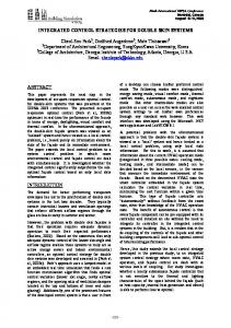
The engine model in the FORTRAN simulation is represented as a component level model (CLM), so called because the major components of the engine are individually modeled and assembled together (see Figure 1). The components of this engine model consist of a two-stage high-pressure ratio fan with variable inlet stator vanes, core driven fan (CDF) with independent hub and tip stator vanes, high-pressure axial compressor, combustor, highand low-pressure turbines, afterburner, and nozzle components. Also included are forward blocker doors and an aft variable area bypass injector (VABI), giving the engine variable cycle capability [6]. The CLM uses low-pressure and high-pressure rotor speeds, as well as average hot section metal temperature (measured from aft of the combustor to HPT) as state variables. The integration of these state variables occurs within a while loop in order to achieve mass, energy, and momentum balance within a certain tolerance.
This paper will discuss the development and use of the two tools. First, a description of the engine model that was implemented in NPSS and used to validate the tools will be described. Next, a description and validation results will be discussed for each tool. It is worth noting that development of the LMG began prior to this study; whereas, the generic controller interface was, however, developed for this study. This paper will present data verifying the generic controller interface’s ability to provide communication between NPSS and a control development platform; and, the LMG’s ability to accurately approximate the dynamics of a nonlinear model. Finally, the paper will conclude with a summary of results and suggestions for future work.
Also shown in Figure 1 are the actuator variables and some of the sensor variables used by the controller. The actuator variables, listed above the engine diagram, include the fan variable inlet stator vanes (STP2), forward blocker door area positioning (A14), core driven fan tip stator vanes (STP27D), high-pressure compressor and core driven fan hub stators vanes (STP27), burner fuel flow (WF36), aft VABI area positioning (A16), afterburner fuel flow (WF6), and nozzle throat and exit area positioning (A8 and A9, respectively). There are many sensors located throughout the engine, as shown in Figure 1, below the engine diagram. The sensors are used by the controller in this model measure fan inlet temperature (T2) and pressure (P2), low-pressure spool speed (XNL), high-pressure compressor inlet temperature (T27) and pressure (P27), high-pressure spool speed (XNH), high-pressure compressor exit temperature (T3) and static pressure (PS3), low-pressure turbine
Engine Model Description The baseline engine model that was selected for validating the control design tools that were developed was a previously validated FORTRAN-based model of a modern highpressure ratio, dual-spool, low bypass, militarytype variable cycle engine model, with a digital controller. This engine model (shown in Figure 1) is a nonlinear, low bandwidth,
NASA/TM—2004-212945
2
blade temperature (T5B), bypass duct static pressure at the mixing plane (PS15), lowpressure turbine exit temperature (T56) and static pressure (PS56).
Generic Controller Interface To facilitate effective control design using NPSS, a generic controller interface was developed to provide communication between NPSS and control development platforms. Via this interface, a control loop could be developed and tested while using an NPSS engine model as the plant. The result would be a control loop that is able to regulate the performance behavior of the NPSS plant. Conceptually, the interface would allow any control development software (e.g.; MATLAB/ Simulink, MATRIX X, or EASY5) to communicate with NPSS. For the purpose of this task, the interface provided communication between MATLAB/Simulink and NPSS. The use of MATLAB and Simulink will be referred to for illustration purposes only. At the time this report was written, the code for other control software environments to communicate with NPSS had not been written. A flexible feature of the interface is that any number of control loops can be allowed to interface with an NPSS model. For example, one could have a fuel flow and an Active Clearance Control model communicating with an NPSS engine model via the same interface. A constraint that was placed on the development of the interface was that the NPSS executable should not be recompiled with MATLAB code. The thought was to keep the NPSS executable as generic as possible.
The steady-state implementation of the NPSS generic military-type CLM simulates the fan, core driven fan, high-pressure compressor, combustor, high-pressure turbine, low-pressure turbine, mixer, afterburner, and nozzle. In addition, it models the bypass splits aft of the fan and forward of the core driven fan, bypass dynamics, and bleeds. The full dynamics of the variable geometries (i.e.; inlet guide vanes, VABI, and the forward blocker door) were not modeled because their full schedules were difficult to identify and extract from the baseline FORTRAN model. The fan and high-pressure compressor maps were extracted, but for a fixed inlet guide vane schedule; the core driven fan map was valid for a limited inlet guide vane range. The turbine maps used were scaled in-house maps. Although the NPSS implementation does not model all of the same components of the baseline CLM, steady state results show that it is a reasonable approximation. Some of the steady state parameters are shown in Figure 2. Each plot in Figure 2 shows a point-wise trend of the baseline model and NPSS generic military-type CLM steady state behavior for each power lever angle (PLA) value. Both models were run at the same constant value of burner fuel flow and fan airflow for each PLA value, and the remaining plots show the steady state responses of both models to this input. The maximum absolute error for normalized thrust is ~0.021; the maximum absolute error for normalized core driven fan pressure ratio is ~0.029; the maximum absolute error for normalized nozzle throat exit area is ~0.013. Similar results were seen in other steady state parameters. Because of this type of steady state performance, it was felt that the NPSS generic military-type CLM was sufficiently modeled to use in the remainder of the study.
NASA/TM—2004-212945
The following discussion is a description on how the generic controller interface is operated. To validate the operation of the interface, a comparison of transient results was conducted between the NPSS engine model and a Simulink-based implementation of the FORTRAN engine model. The Simulink implementation, called the Modular Aero-Propulsion System Simulation (MAPSS), models both the CLM and the digital controller used in the FORTRAN simulation. For the transient comparison, the controller from MAPSS will be used to control the NPSS engine model. A more detailed description of the interface may be found in the Generic Controller Interface User Guide, which is currently under development. A description of the development of MAPSS may be found in reference [7].
3
the NPSS model to initialize the control model. It would be done by first allowing the model to run steady state and then declare an instance of the interface. The values from the steady state run would be used as initial inputs for the control model. This ensures that when the NPSS model begins a transient, both models will be starting at the same point.
The controller interface consists of two parts: a definition file and the control model declaration in the NPSS model file. The definition file is a simple text file that sets up communication between NPSS and MATLAB (see Figure 3). It allows the user to specify the control development platform (e.g.; ML = MATLAB), the NPSS engine model name, the number in inputs and outputs, and the amount of error reporting. There are seven levels of error reporting that range from showing no screen output or errors (error code 0) to showing all screen output and errors (error code 6). This file is also used to establish a relationship, or mapping between the MATLAB/Simulink control model variables and the corresponding NPSS variables. The input and output variables for Simulink and NPSS are entered in the following manner:
For GenControls operation, at the start-up of NPSS the definition is parsed to determine the control development platform via the control platform designator. Next, it takes the controller and NPSS engine model filenames to modify them with the correct extensions for parsing, and then it sets the user-defined error reporting level. GenControls then maps each input and output variable defined in the definition file to an array of NPSS data storage structures, which allow for mixed variable types. The size of this array of structures is determined by the number of inputs and outputs specified in the definition file. Each structure will contain the variable type, control model variable name, the corresponding NPSS variable name (as defined in the definition file), and the value of the variable. At this point, the parsing setup routine is complete. GenControls then goes to the NPSS model file to find a declared instance of the control model using this interface. NPSS, then, runs the engine model at steady state to determine the initial conditions for a transient run. After the steady-state run, an instance of the control model is declared. The GenControls interface is called to initialize the Simulink control model with the results from the steady-state run. Figure 4 is an example of a defined instance of a control model, using GenControls, in a NPSS model file. In this example, the name of the control model is xcontrol. Once the control model is initialized, NPSS enters the transient phase of the engine model run. The instance contains a preexecute function that prepares, and then sends the NPSS data, after running one transient time step, to the control model via the data structure. Once that data is received, GenControls starts a persistent instance of MATLAB, opens the control model then runs it to process the data. The control model processes the data for one time step and then stores the data in the NPSS data structure. The control model data is
Input: Output:
This section of the definition file is key because it specifies what data is “going to” and “coming from” the control model. The file is saved with the same name as the control model file with a .def extension (e.g.; .def). The interface uses the name of the controller as a reference key to the associated files used by NPSS and the control model. The next part of the interface is declaring a control model in the NPSS engine model file. There are two types of interfacing methods: the GenControls and the ExtControl. The GenControls interface is a dynamically loadable module (DLM) that allows NPSS to run MATLAB. It was developed to be “cloned” for use with other control development platforms. The ExtControl interface is also a DLM that runs NPSS in parallel with MATLAB. The main task of both interfacing methods is to set up the communication link between MATLAB and NPSS, prior to either system running. Using either interfacing method, code can be written in
NASA/TM—2004-212945
4
up the output data and passes it to the NPSS model so that it can run the next time step. This process is continued until the model run has completed.
received by a postexecute function, and applies it to the NPSS model. The NPSS engine model runs the next time step then passes the data back to the control model via GenControls. These last few steps are repeated until the model stop time is reached. When the run is complete, NPSS closes MATLAB.
To create a transient NPSS model, dynamic data, such as the inertias for the low- and high-pressure spools, was added to the steady-state model of the NPSS model of the generic, military-type engine that was described above. The information for the third state (average metal temperature) was not added because the thermal inertias could not be properly extracted from the baseline engine model. To demonstrate the use of the interface, the transient model was run in a closed-loop with the control model from MAPSS. The interface used in this test was GenControls. The operating conditions for the run consisted of a PLA ramp from 35° to 45° at sea level static conditions. At the same operating point the closed-loop results were compared to results from MAPSS and open-loop results of the NPSS engine model, using input data tables generated from MAPSS. Because MAPSS closely models the dynamics of the baseline FORTRAN model, it was used as a reference model for this comparison. A standard method for running transients with NPSS models is to use input data tables; so, it was used as the other reference model. This was done because it was desirable to see how the NPSS model behaved when it was being controlled by a control model and following an input table. The data tables that the NPSS engine model used included actuator commands for combustor fuel flow, nozzle throat exit area, bypass duct exit area, ambient temperature and pressure, and fan inlet temperature and pressure. The NPSS engine model was not expected to produce perfect transient results in comparison to MAPSS. However, it was hoped that the transients of the NPSS model would follow the trends of the MAPSS results. Figure 6 shows some selected results. From the results, one can see that the selected performance indicators achieved expectations, as all three models were very close to the same ending steady state point and, for the most part, followed the MAPSS trend nicely. Other performance indicators showed similar results. Overall, however, it is shown that the interface is capable allowing the necessary communication
Using the ExtControl interfacing method, a script M-file is used to pass data and triggers between the two systems, as opposed to the array of data storage structures used in the GenControls. In addition, ExtControl does not run MATLAB; therefore, a working MATLAB environment must be opened in the standard way in the directory where the control model, the file passing script M-file, and the NPSS model are located. Before the NPSS model is run, the file passing script M-file must be running in MATLAB. At the start-up of NPSS, the definition file will be parsed in the same manner as the GenControls interface, and then it will find a declared instance of the control model in the NPSS model file. The instance is a reversed version of the one described in GenControls. Figure 5 is an example of defining an instance of ExtControl in an NPSS model file. In this example, the name of the control model is xcontrol. After completing the steady state runs, NPSS will enter the transient run mode. After the first time step in this mode NPSS will then pause and wait for the values from the controller to be returned. The postexecute function, in the ExtControl instance, prepares the NPSS model data to be used by the control model. ExtControl saves the data in an input file and places it and a trigger file into the working directory. The trigger file tells the file passing script in MATLAB that an input file is ready to be processed. Both files are picked up by the file passing script M-file. The script then runs the control model; saves the output values in an output file, and then save it along with another trigger file into the same working directory. The second trigger file tells ExtControl that the output is ready to be processed. The preexecute function, also in the ExtControl instance, picks
NASA/TM—2004-212945
5
between an NPSS engine model and an external control software platform.
∂x& A= ∂x
∂x& B= ∂u
A salient challenge in performing this transient run was aligning the time steps between NPSS and MATLAB/Simulink. The MAPSS controller block models both the engine control system and the actuators, of which run at two different update rates of 50 Hz and 2500 Hz, respectively. As stated before, the NPSS model runs one time step before sending data to the controller for calculation of the next control signal. The issue was that each time the controller would run, it would not maintain a time history of all the data received so that it could give the NPSS model the proper control signal. The solution used was to archive the time history inside the interface then run the control model based on the time history. The results shown in Figure 6 were produced using this approach. Although it worked, this is not a viable solution because the time to run the simulation increases factorially. A more viable solution must be found.
∂y C= ∂x
∂y D= ∂u
The matrices represent a change in the state derivative variables ( x& ) and selected output variables (y) with respect to small perturbations in the state variables (x) and model input variables (u). The default perturbation size for the LMG is 0.5%. These matrices are implemented as a linear model using the following state-space equations:
x& = Ax + Bu y = Cx + Du
(1)
(Output Equation)
(2)
A comparison was conducted to show how accurately the LMG modeled the dynamics of the nonlinear NPSS generic military-type CLM. A linear model was created of the NPSS model at the base operating point of PLA = 45°, at sea level static conditions. The nonlinear NPSS generic military-type CLM was run transiently, starting at PLA = 45° then increasing the fuel flow by 3%. The same input was then applied to the generated linear model. The comparison results between the linear and nonlinear models are shown in Figure 7 for selected parameters. The figure shows that the linear model created is a very close approximation of the nonlinear model for the given operating conditions. Other parameters for this and other operating conditions showed similar results.
Linear Model Generator Numerous linear analysis tools have been developed in classical and modern control theory. The conventional control system design approach is to base it upon a single linear model of a plant system, or a series of linear models connected in a piecewise continuous fashion. In order to further enhance the NPSS control development capabilities, a linear model generator (LMG) has been developed and implemented into the NPSS environment. The LMG was used to generate several linear models of the NPSS generic military-type CLM.
Conclusion This paper presented two control development tools that have been developed and integrated into the NPSS environment. The study was conducted using an NPSS model of a generic military-type engine CLM. This engine model had known limitations, such as how the dynamics of the variable geometries were modeled. In spite of this, results from steady state runs showed that the model was sufficient to use.
The LMG is able to create a single linear approximation of a full nonlinear NPSS model about a base operating point. The linear approximations consist of four Jacobian matrices, generated by using small perturbation theory, and are defined as:
NASA/TM—2004-212945
(State Equation)
6
2. Lytle, J.K., “The Numerical Propulsion System Simulation: A Multidisciplinary Design System for Aerospace Vehicles,” NASA/TM—1999209194, July 1999.
The generic controller interface allows communication between NPSS and a control development platform. It was found that the interface was able to provide communication between NPSS and control development platforms allowing a NPSS engine model to responded to given control demands. It was found, that Simulink was not able to maintain a time history of all input received, which caused the control model to produce incorrect demands. A means of archiving the input was found; however, a more permanent solution is currently being looked at. The other control design tool integrated into NPSS was a linear model generator (LMG), which can create a linear model of a nonlinear NPSS model about a given operating point. It was found that the LMG was able to closely approximate a nonlinear model for a given operating point.
3. Reed, J.A., Afjeh, A.A., “An Interactive Graphical System for Engine Component Zooming in a Numerical Propulsion System Simulation,” AIAA 95–0118, 33rd Aerospace Sciences Meeting and Exhibit, Reno, NV, January 1995. 4. Veres, J.P., Lavelle, T.M., “Mean Line Pump Flow Model in Rocket Engine System Simulation,” NASA/TM—2000-210574, November 2000. 5. Adibhatla, S., Gastineau, Z., “Tracking Filter Selection and Control Mode Selection for Model Based Control,” AIAA 94–3204, 30th Joint Propulsion Conference and Exhibit, Indianapolis, IN, June 1994.
In an effort to continue increasing the ability of NPSS for use in control development, more tools should be added, such as the ability to create bode, Nyquist, and root locus plots.
6. Adibhatla, S., Johnson, K.L., “Evaluation of Nonlinear PSC Algorithm on a Variable Cycle Engine,” AIAA 93–2077, 29th Joint Propulsion Conference and Exhibit, Monterey, CA, June 1993.
References 1. Veres, J.P., “Overview of High-Fidelity Modeling Activities in the Numerical Propulsion System Simulation (NPSS) Project,” NASA/TM—2002-211351, June 2002.
NASA/TM—2004-212945
7. Parker, K.I., Guo, T.-H., “Development of a Turbofan Engine Simulation in a Graphical Simulation Environment,” NASA/TM—2003212543, August 2003.
7
Appendix: Figures
Core Driven Combustor Fan
LPT
Afterburner
Nozzle Fan
HPT
HPC
Mixer
Figure 1: Schematic of CLM.
Burner Fuel Flow vs. PLA
Net Thrust vs. PLA
Fan Air Flow vs. PLA
1
1
0.8
0.9
1 0.9 0.8
0.6
0.8
0.4
0.7
0.2
0.6
0.7 0.6 0.5
CDF Pressure Ratio vs. PLA 1
0.4 30
Nozzle Throat Exit Area vs. PLA 1.1
40 PLA
50
Baseline Model NPSS
0.9 1.05 0.8 0.7 1 0.6 30
40 PLA
50
30
40 PLA
50
Figure 2: Normalized steady state results of selected performance parameters.
NASA/TM—2004-212945
9
Control platform designator
ML .mdl 10 5 0 Input: real real real real real real real real real real
No corresponding NPSS variable defined.
NPSS model name
xm Ambient.MN pc PC alt Ambient.alt dtamb Ambient.dTamb sfc PERF.TSFC sm27d CDF.SMN sm27 HPC.SMN xn2c LP_Shaft.Nmech xn25c HP_Shaft.Nmech pcn2
Output: real wf36n_ic Burner.Wfuel real a8act_ic Nozzle.Ath real a16act_ic Duct16a.Aphy real a14act_ic Splitter1.Aphy real stp2act_ic
Figure 3: Example Definition file.
//------------------------------------------------------------// Controller //------------------------------------------------------------Element GenControls xcontrol{ void preexecute (){ GCsetInputValue("pc", PC); GCsetInputValue("alt", Ambient.alt); GCsetInputValue("dtamb", Ambient.dTamb); GCsetInputValue("sfc", PERF.TSFC); GCsetInputValue("sm27d", CDF.SMN); GCsetInputValue("sm27", HPC.SMN); GCsetInputValue("xn2c", LP_Shaft.Nmech); GCsetInputValue("xn25c", HP_Shaft.Nmech); GCsetInputValue("xm", Ambient.MN); } void postexecute(){ Nozzle.Ath = GCgetOutputValue("Nozzle.Ath"); Duct16a.Fl_I.Aphy = GCgetOutputValue("Duct16a.Aphy"); Splitter1.Fl_I.Aphy = GCgetOutputValue("Splitter1.Aphy"); } }
Figure 4: GenControls interface instance declaration in an NPSS model file.
NASA/TM—2004-212945
10
//----------------------------------------------------------// Controller //----------------------------------------------------------Element ExtControl xcontrol{ void postexecute (){ GCsetInputValue("pc", PC); GCsetInputValue("alt", Ambient.alt); GCsetInputValue("dtamb", Ambient.dTamb); GCsetInputValue("sfc", PERF.TSFC); GCsetInputValue("sm27d", CDF.SMN); GCsetInputValue("sm27", HPC.SMN); GCsetInputValue("xn2c", LP_Shaft.Nmech); GCsetInputValue("xn25c", HP_Shaft.Nmech); GCsetInputValue("xm", Ambient.MN); } void preexecute(){ Nozzle.Ath = GCgetOutputValue("Nozzle.Ath"); Duct16a.Fl_I.Aphy = GCgetOutputValue("Duct16a.Aphy"); Splitter1.Fl_I.Aphy = GCgetOutputValue("Splitter1.Aphy"); } }
Figure 5: ExtControl interface instance declaration in an NPSS model file.
Thrust
Low-Pressure Spool Speed
1.5
High-Pressure Spool Speed 1.05
1.06
1.4
1.04
1.05 1.04
1.3
Closed-Loop NPSS MAPSS Open-Loop NPSS
1.03
1.03 1.2
1.02 1.02
1.1
1.01
1.01
1
1
1
HPC Exit Temperature
HPC Inlet Tempearature 1.04
1.09
1.035
1.08
1.03
1.07
1.025
1.06
1.02
1.05
1.015
1.04
1.2
1.15
1.1
1.03
1.01
1.02
1.005
1.05
1.01
1 0
LPT Exit Temperature 1.25
1
2
3 time
4
5
1 0
1
2
3 time
4
5
1 0
1
2
3
4
5
time
Figure 6: Normalized transient results of selected performance parameters.
NASA/TM—2004-212945
11
Thrust
1.005 1
0.99
1
0.998 0.997
0.995
0.98 0.975
0.996
0.99 HP Spool Speed
1.001
0.995 % Corr. LP Spool Speed
Fan Exit Static Pressure
1
1
1
0.999
0.999
0.998 0.998
0.995
0.997
0.997
0.996
0.996
0.995
1
Nonlinear output State-space output
0.999
1
0.985
LP Spool Speed
1.001
1.005
0.995
1.001
TSFC
1.01
CDF Inlet Pressure
1.001
0.99 CDF Inlet Temperature
1
HPC Inlet Pressure
1 0.995
0.995
0.999 0.998
0.99
0.99
0.997 0.985 0
5
10 time
15
20
0.996 0
5
10 time
15
20
0.985 0
5
10 time
Figure 7: Linear to Nonlinear Model Comparision.
NASA/TM—2004-212945
12
15
20
Form Approved OMB No. 0704-0188
REPORT DOCUMENTATION PAGE
Public reporting burden for this collection of information is estimated to average 1 hour per response, including the time for reviewing instructions, searching existing data sources, gathering and maintaining the data needed, and completing and reviewing the collection of information. Send comments regarding this burden estimate or any other aspect of this collection of information, including suggestions for reducing this burden, to Washington Headquarters Services, Directorate for Information Operations and Reports, 1215 Jefferson Davis Highway, Suite 1204, Arlington, VA 22202-4302, and to the Office of Management and Budget, Paperwork Reduction Project (0704-0188), Washington, DC 20503.
1. AGENCY USE ONLY (Leave blank)
2. REPORT DATE
3. REPORT TYPE AND DATES COVERED
Technical Memorandum
February 2004 4. TITLE AND SUBTITLE
5. FUNDING NUMBERS
Integrated Control Modeling for Propulsion Systems Using NPSS WBS–22–765–10–05
6. AUTHOR(S)
Khary I. Parker, James L. Felder, Thomas M. Lavelle, Colleen A. Withrow, Albert Y. Yu, and William V.A. Lehmann 7. PERFORMING ORGANIZATION NAME(S) AND ADDRESS(ES)
8. PERFORMING ORGANIZATION REPORT NUMBER
National Aeronautics and Space Administration John H. Glenn Research Center at Lewis Field Cleveland, Ohio 44135 – 3191
E–14385
9. SPONSORING/MONITORING AGENCY NAME(S) AND ADDRESS(ES)
10. SPONSORING/MONITORING AGENCY REPORT NUMBER
National Aeronautics and Space Administration Washington, DC 20546– 0001
NASA TM—2004-212945
11. SUPPLEMENTARY NOTES
Prepared for the 39th Combustion/27th Airbreathing Propulsion/21st Propulsion Systems Hazards/3rd Modeling and Simulation Joint Subcommittee Meeting sponsored by the Joint-Army-Navy-NASA-Air Force Interagency Propulsion Committee (JANNAF), Colorado Springs, Colorado, December 1–5, 2003. Khary I. Parker, James L. Felder, Thomas M. Lavelle, Colleen A. Withrow, and Albert Y. Yu, NASA Glenn Research Center; and William V.A. Lehmann, Modern Technologies Corporation, Middleburg Heights, Ohio 44130. Responsible person, Khary I. Parker, organization code 5530, 216–433–8442. 12b. DISTRIBUTION CODE
12a. DISTRIBUTION/AVAILABILITY STATEMENT
Unclassified - Unlimited Subject Categories: 07 and 08
Distribution: Nonstandard
Available electronically at http://gltrs.grc.nasa.gov This publication is available from the NASA Center for AeroSpace Information, 301–621–0390. 13. ABSTRACT (Maximum 200 words)
The Numerical Propulsion System Simulation (NPSS), an advanced engineering simulation environment used to design and analyze aircraft engines, has been enhanced by integrating control development tools into it. One of these tools is a generic controller interface that allows NPSS to communicate with control development software environments such as MATLAB and EASY5. The other tool is a linear model generator (LMG) that gives NPSS the ability to generate linear, time-invariant state-space models. Integrating these tools into NPSS enables it to be used for control system development. This paper will discuss the development and integration of these tools into NPSS. In addition, it will show a comparison of transient model results of a generic, dual-spool, military-type engine model that has been implemented in NPSS and Simulink. It will also show the linear model generator’s ability to approximate the dynamics of a nonlinear NPSS engine model.
14. SUBJECT TERMS
15. NUMBER OF PAGES
Digital simulation; Dynamic system; Models; Computer aided design; Control system design; Engine control; NPSS 17. SECURITY CLASSIFICATION OF REPORT
Unclassified NSN 7540-01-280-5500
18. SECURITY CLASSIFICATION OF THIS PAGE
Unclassified
19. SECURITY CLASSIFICATION OF ABSTRACT
17 16. PRICE CODE 20. LIMITATION OF ABSTRACT
Unclassified Standard Form 298 (Rev. 2-89) Prescribed by ANSI Std. Z39-18 298-102