developers for designing wind energy conversion systems, where ANN based controller is much faster ... efficiency of converting wind power to electrical power,.
Integrated Controller For Fixed Speed, Grid Connected Wind Turbine, Based On Neural Networks. A. Hashad1, F.Z.Amer2, A.M. El-Garhy2, A.E.Youssef3, S.M. Aly4 1. Al-naeim Consultancy, Qassim University – Buraydah. KSA. 2.Control Engineering Department. Helwan University. Cairo, Egypt. 3. Information systems Department, King Saud University. Ryadh KSA. 4. Wind Power studies department New and Renewable Energy Authority. Cairo, Egypt. Abstract: Electrical power production is the main target required from wind turbines. This paper describes an approach for wind turbine controller as a vital part of the turbine, where this controller is based on Artificial Neural Network technique and a control scheme has been applied and validated by detailed simulation in MATLAB 6.5/Simulink. The proposed controller enhances the reactive power affected by electrical grid voltage and/or load disturbances where the controlled variables for the controller are system voltage and power production. Final results were compared with practical database of wind turbine runs by conventional controllers without applying ANN, and found positive. The controller model is useful for wind energy developers for designing wind energy conversion systems, where ANN based controller is much faster and adaptive to maintain maximum power conversion efficiency which appears steady at maximum in the same area of the power/wind speed curve during load or wind sudden variances. Key words: generator, Capacity factor, Artificial Neural Network, simulation, wind turbine controller, voltage stability.
1. Introduction: Control system in wind turbines plays important role to guarantee “Fail Safe” operation of the machine; this is done by integrating machine stability with utilizing the machine design for maximum power production. Wind Power Conversion depends essentially on the power coefficient, “Cp” of the machine which translates the efficiency of converting wind power to electrical power, where it is the ratio of power produced by a wind turbine to the power in a reference area of free wind stream, as will be explained later. From this pivotal point any control system starts to be designed, and first portion to be studied in the system is the generator. Conventional controllers uses all possible parameters to guarantee perfect aerodynamic power control which is definitely needed at variable wind speeds to limit the input power to the wind turbine, but in case of applying ANN technique, the controller can handle any variances or disturbances in operational parameters in shorter time to reach steady state case, also a turbine can continue in production mode without disconnecting from grid as currently happens in practical. This approach differs than conventional controlling in focusing on voltage stability towards supply variances and load fluctuations under continuous connection to power grid. Where “ANN” is used in the controller structure to support the required “learning” for grid supply state to guarantee perfect capacitance bank value required to balance the system voltage against any turbulences of grid supply voltage or load unbalances. This is done by perfect exploitation of capacitance stages in reactive power module, resulting consequent improve in power production stability. [1-3]. For steady-state calculations of wind turbine, mechanical power can be determined by [4].:
1 Pm = ρArCp (1 / ω )ν 3 2
(1)
Where “ω” is the rotational speed of wind turbine blades, and it is called rotor speed, this rotational movement is transported to a gear box through a lowspeed shaft. Then the speed is converted to actual rotational speed feeding the generator by high speed shaft from the other side of the gearbox, this speed is the synchronous speed “ωs” once the generator is connected to grid. ”ν” is the wind speed, “ρ” is the air density and “Ar” is the area swept by rotor. General behavior of a wind energy conversion system can be described in two main relations, power coefficient as a function of tip speed ratio “µ” and mechanical power as a function of wind speed, as shown in Fig. 1, where µ is defined as the ratio between the rotational speed of the blade tip and the actual velocity of the wind. [1]. Section 2 of this paper, explains the Self Exited Induction Generator “SEIG” design, in section 3, an abbreviated explanation for conventional PI controller is mentioned. Section 4, explains the proposed ANN controller, section 5 Shows the conclusion & finally the actual results of this integrated system compared with on land running turbines in Zafarana wind farm on red sea coast which currently contains more than 400 fixed speed, grid connected wind turbines, is presented in section 6.
Fig. 1
2. Grid Connected SEIG Dynamic Modeling: Self Excited Induction Generators are used for autonomous applications especially in wind power systems. The lower unit cost, brushless cage rotor
construction, absence of a separate DC source and better transient are its main advantages over the conventional alternators. In this approach, the control is applied on SEIG, where an appropriate capacitor bank is connected across supply terminals of the generator by means of ANN decision. This helps to achieve balance on voltage and current components by compensating the VAR demand for the machine in good timing, but the important difference in this case “comparing with conventional controllers” is the fast and adapted response by ANN to maintain the stability to the turbine operation. Parameters of this research case study machine are as per Vestas fixed speed, grid connected wind turbine: V60/660 KW: Generator rated voltage is 690 V/560A, 50 HZ working frequency, generator stator resistance Rs=0.0048Ω, Rotor resistance Rr=0.0087Ω, rotor reactance Xr=0.0897Ω, and stator reactance Xs=0.068Ω. Modeling for the induction generator under study was presented in direct/quadrature reference, “d-q form”, where it is easier to get the complete solution, transient and steady state of the self-excitation by this presentation. The following mathematical differential equations describe the generator by applying Kirchhoff’s voltage law to the equivalent circuits of the SEIG as shown in Fig. 2; a) in quadrature axis and b) in direct Axis, we get the following [1],[5],[6]:
Regarding the load current and the relation with the capacitor bank value, the following equations will clarify this: (4) ϕds = − Xls * Ids + Xm( Idr − Ids)
ϕqs = − Xls * Iqs + Xm( Iqr − Iqs)
(5) Where: φds, φqs are stator flux linkage in direct and quadrant axis respectively (Weber), φdr, φqr are rotor flux linkage in direct and quadrant axis respectively (Weber), Xls is the stator reactance (Ohm) and Xm is magnetization reactance (Ohm).
2.3 Current & Capacitance: d Vds − Xl * ( ILds ) dt d Ids = C * (Vds) + RL dt d Vqs − Xl * ( ILqs ) dt d Iqs = C * (Vqs ) + dt RL
Vds − ( RL * ILds) XL 600 Vqs − ( RL * ILqs ) ILqs = ∫ XL 0
ILds = ∫
(6)
(7)
600
(8)
0
(( Ids − Iqs)
(7)
)
2.1 Stator Voltage:
Im =
Despite SEIG is preferred to be used in non conventional power conversions, it has also considered being variable voltage, variable frequency source, so in order to handle the power utility connection, it is necessary to guarantee stable and steady voltage and frequency of the system. Voltage can be driven as:
Where, RL is load resistance (Ohm), ILds and ILqs are load current in direct and quadrature axis respectively (Ampere) and Im is the mutual Current (Ampere). The capacitor bank consists of 4 stages, the effective capacitance C; is determined according to the reactive power produced and the load estimated on the output terminals and its value to be applied by the controller, [2],[3],[7].:
ω d ϕds )ϕqs + ( ) ωb dt ωb d ϕqs ω Vqs = − Rs * Iqs − ( )ϕds + ( ) ωb dt ωb Vds = − Rs * Ids − (
(2)
2
+ ( Idr − Ids) 2
(10)
(3)
Where Vds, Vqs are stator voltage in direct and quadrate axis respectively (Volt). And Ids, Iqs are stator current in direct and quadrature axis respectively (Ampere). ω, is the rotor speed (rpm) and ωb is the base velocity ( ωb =2πf, and equals to 314.16 as per 50 Hz working frequency).
2.2 Flux Linkage: The initiation of the self excitation process is a transient phenomenon and it is better understood if analyzed using instantaneous values of current and voltage in d-q axis model to investigate the process of current and voltage build up during self excitation, where the main variables of the machine in rotating frame are flux linkages and load perturbations [1],[5].
Fig.2
C max C= (1 − λ ) 2 + δλ2
(
)
(11)
Where, δ is the ratio between maximum to minimum value of capacitor bank and λ is the duty cycle value which is the portion of time during which ANN switches from ON state to OFF state or switches between capacitance stages. [1],[2].
2.4 Power & Torque Presentation: Aerodynamic lift and drag force on the rotor blades, produces the torque on the turbine rotor, the mechanical power produced by a rotor is purely a function of the geometry and the incident velocity. The CP for any fixed rotor geometry is a well-prescribed function of the blade tip speed ratio with a single maximum value. The torque produced by the rotor can be controlled by varying the blade pitch angle; which is defined as the deviation angle of the blade away from its longitudinal axis. This is translated by the following equations [7],[6].: (12) Tm = Pm / ωb & (13) Te = (ϕds * Iqs) − (ϕqs * Ids) Where, Tm and Te are mechanical and electrical Torque respectively. Basically, rotor rotation is a balance between the aerodynamic torque applied by the wind and the electrical torque applied by the generator. The power coefficient is a measure of the mechanical power delivered by the rotor to the turbine’s low speed shaft. It is frequently defined as the ratio of the mechanical power to the power available in the wind; tip speed ratio is the real measure of power of the wind a turbine can gain. This is presented in next equation (14), [7].: π ( µ − 3 − [0.00184( µ − 3) β ] Cp = (0.44 − 0.0167 β ) * sin 15 − 0.3β Tip speed ratio
ω=
1500
ωb
µ=
ω * Rr ν
The voltage or mechanical power errors are used as an input variable to the PI controller, then the output is used to regulate the duty cycle of the switching capacitor bank in the reactive controller. The output of active controller is utilized to tune up the pitch angle of the wind turbine, which leads to adjust the system frequency [1]. The duty cycle and the pitch angel values are adjusted from the setting of the PI gains. The mathematical model of SEIG / WECS is simulated using MATLAP / SIMULINK software. A suddenly disturbance due to change for the nearest load is simulated
4. Artificial Neural Network “ANN”; the reactive controller: Neural networks, with their remarkable ability to derive meaning from complicated or imprecise data, can be used to produce final decisions for problems that are too complex to be noticed by either humans or other computer techniques. A trained neural network can be thought of as an “expert” in the category of information it has been given to analyze. This expert can then be used to provide projections given new situations of interest & answer “what if” questions.
And the rotor speed:
∫ 2 H * (Tm − Te − (ω * F ))
(15)
Fig.3.a
0
Where H is the equivalent inertia constant for both wind turbine and induction generator rotors and F is the friction factor [1],[5]. SEIG equations are presented by Matlab Simulink to form the equivalent circuits as follows respectively: stator voltage and current in direct axis, stator flux in quadrant axis, electrical / mechanical power, synchronous speed and load current as shown in Fig. 3. Also transmission line presentation for grid connection is shown in Fig.4.
Fig. 3.b
3. Proportional Integral Controllers The Proportional plus Integral (PI) controller is a conventional controller which has two gains to adapt the output of the controller. The first gain is called (KI) Integral gain, and the second one is called (KP) Proportional gain. It is applied on the system under study by using fixed gains. Both the integral gain and proportional gain are chosen with reference to terminal voltage error (eV) or mechanical power error (Pmv). Where (KIv) is the integral gain of PI reactive controller and (KPv) is the proportional gain of PI reactive controller. But (KIF) is the integral gain of PI active controller and (KPF) is the proportional gain of PI active controller.
Fig. 3.c
Fig.3.d
Fig.3.e
Induction machine connected to the grid operates as externally excited induction generator, while taking the excitation current from the grid, for which the operating speed of the machine must be greater than the synchronous speed. The output voltage and frequency should not change with loading conditions but active power generated by the machine is a function of slip. SEIG connected across the capacitor bank when driven by the wind within the limits of productive speeds. Under these conditions the capacitor bank meets the total reactive power requirements of the machine and load. Active power generated by the rotor is delivered to the load through stator. The input of the ANN will be voltage error signal; the main goal of the control is to maintain this voltage signal steady.
Fig.3.f
Fig. 5
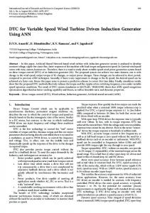
Fig.4: This is done by ANN computations which are carried out in parallel, and special hardware devices are being designed and manufactured to take advantage of this capability. The control scheme supposed to be used for controlling the operation of the wind turbine, uses “Feed forward propagation”, where the main parameter which ANN monitors and reacts is the difference in voltage across generator terminals due to grid unbalance fluctuations. This reaction is adapted by Back Propagation looping, where the voltage signals traveling in both directions of Input & Output neurons by introducing loops in the network. Feedback is highly recommended to get perfect “trained” ANN output decision, which is considered to be very powerful and can get extremely complicated, by this design, the network will act dynamically; and the state is changing continuously until an equilibrium point is achieved, and will be remained until the input changes and a new equilibrium needs to be found.[2],[8],[9]. 4.1 Design of ANN to control SEIG voltage stability
This is done by applying the output of the network on the capacitor bank control to change its value accordingly [1],[10]. As illustrated in Fig. 5 the input layer of ANN design consists of three nodes, their inputs are firstly the initial data of the network which is the error in voltage signal, secondly the previous record of the error to be compared with the current value, and this is the main “learning target” for perfect adaptation of the output, lastly the previous record of the ANN output. The inputs then are subjected to a hidden layer, and then, weights of the networks modify the hidden layer intermediate results. Finally the output layer decides the best decision for the appropriate value corresponds to the correct capacitance of reactive compensator. Error calculation is done in all stages. That is, the neurons in hidden layer receives the adapted input signals from each node of the input layer, then it collects all and apply a “tansig” logistic function which was chosen as best try & error resulting function, then delivers the result after modifying the weights again plus error calculations to last stage. All these steps will be described mathematically as follows: NNout = ( Fa *Wa) + ( Fb *Wb) + Bc (16) Adaptation on weights affecting on the input signal of output layer neuron (Wa & Wb) are described as: Wa = (Wai) + ( Fa *αr * De) + Bc (17)
Wb = (Wbi) + ( Fb *αr * De) + Bc The error calculation for output layer:
(18)
De = (Ve * NNout ) * (1 − NNout )
(19) Regarding the Input layer adaptation, the weights and error calculations for hidden layers are as follows: (20) Dec = (Wa * De * Fc) * (1 − Fc)
Ded = (Wa * De * Fd ) * (1 − Fd ) Wc = (Wci) + (Ve *αr * Dec) Wd = (Wdi) + (Ve * αr * Ded )
(21) (22)
(23) Where, Nx is an output of neuron x. Ve is the voltage error of applied voltage on generator terminals. Wxi is initial weight value applied on neuron x. Bx is the bios value applied on neuron x. NNout is the output value of the neural network. Doe, Dhe are error calculations for output and hidden layers respectively. Fx is logistic function applied on neuron x output. αr is the learning rate of the network. The multilayer back propagation feed forward NN was used to develop a model that provides a good estimate of magnetization characteristics. [1]. In this network, Ve is used as input and Fc as output for training purpose. The network is set with ‘tansig” activation function at the middle layer and 'purelin' activation function at the output layer. The design of the network and selection of optimum training parameters are performed by trial and error as per practical guide of on line data collected from running turbine. Table 1 shows an example of some practical online data given for some Power (KW)
drops in short period, a manual restart of the controller must be done. This is always causes low power production quality and various stop due to errors during normal operation, even in strong and productive wind speeds. Applying ANN to the controller enhances the performance of the turbine’s operation, this is done in the assumed controller where a sudden disturbance in the grid load and wind speed is conducted to outline the system characteristics' performance and to examine how this system can reaches steady state condition. A simulation for this dynamic case study system is conducted using MATLAB SIMULINK package. In the system under study, the inputs to the controller are voltage, change of voltage (voltage error) and the output of the controller, these perform the duty cycle (λ) which is used to compute the effective capacitor bank value (C) as in equation (11). The duty cycle as a function of controller output is used as an input to semiconductor switches to change the capacitor bank value according to the need for the effective value of the excitation. Accordingly, in the semiconductor switching technique, the terminal voltage is controlled by adjusting the self-excitation through automatic switching for the capacitor bank. Reactive control is required to overcome any disturbances in utility grid voltage during wind turbine operation.
Pitch angle (Degree )
Date/Time
Wind Speed (m/s)
02.06.2008 11:20
9.5
476
-1.2
02.06.2008 11:30
9.9
517
-1.1
02.06.2008 11:50
9.7
503
-1.1
02.06.2008 12:00
12.2
660
5.7
02.06.2008 12:10
12.2
657
5.8
02.06.2008 12:20
11.9
653
4.2
02.06.2008 12:30
12.1
657
5.1
02.06.2008 12:40
12.0
656
4.9
02.06.2008 12:50
11.1
620
1.7
02.06.2008 13:00
12.9
660
7.9
02.06.2008 13:10
12.8
660
8.0
turbine parameters. A presentation of ANN model under test in shown by Matlab Simulink in Fig. 6.
5. Results Practically the conventional controllers of wind turbines, are very slow in responding to wind variations and load disturbances, and under failsafe strategy of this type of controller cause the wind turbine disconnect from grid for a long time “in minutes” until steady state of power and wind parameters are fulfilled then it reconnect the generator again, not only this but also in grid repeated
Fig.6 Table 1. Sample of blade pitch angle value corresponding to the wind turbine parameters at the same instance. A capacitor bank unit is used in stages according to present VAR rating of the machine [1],[3],[5]. The control action can he carried out at any time of the power cycle so that it can provide a smooth variable source of reactive power. This leads to keep a constant terminal voltage equal to the rated value at different loads and different prime-mover speeds. The steady state results obtained are very much acceptable. Applications of an efficient on-line Artificial Neural Network (ANN) based power system stabilizer (PSS) for a wind turbine is
presented. The on-line training technique is used to update the weights and biases of each ANN controller, using the on-line back propagation (BP) algorithm. The ANN utilizes the speed deviation of the associated generator via the BP algorithm to enhance the overall dynamic response. Fig. 7 illustrates the adaptation of applying ANN as an active control to the terminal voltage of the generator, where it help the system at starting of grid connection to reach the steady state faster and smoother than conventional controller. In addition, a sudden impact in voltage was fed to the scheme at time 20 and also derived the voltage to stability faster and smoother. In case of higher voltage drops, ANN can handle more fluctuations with connection to the electrical grid, where the damping period for the rising curve was reduced. This means increasing the turbine availability. But conventional controller In this case disconnects the generator completely from grid until voltage returns to rated values, which may lasts for multiply minutes. Fig. 8 is another successful example for ANN adaptation but here for load current, a fast stability is obtained by ANN in both starting of generation process and in load impact, where Sudden load unbalance is applied on the system and ANN (light line) helps the load current reaches steady state faster than normal case (darker line). On the other hand for active control, the ANN helps the system runs even when subjected to sudden wind speed fluctuation, as shown in Fig. 9 which shows per unit frequency behavior, the system was examined to sudden change in wind speed. Normally the turbine disconnects the generator from grid until a real value for wind speed is achieved, but with ANN a perfect adaptation for the rotor frequency is obtained to reserve the production process while wind speed values varies in large scales. Finally and as a meter for a wind turbine performance a representation for the effect of ANN on the capacity factor is shown in Fig. 10 where the average value for Cp (green line) is higher than the same parameter in case of using conventional controller.
Different control methods of varying degrees of complexity have been proposed and used for the scalar control of induction machine in isolated stand alone wind turbines, where the proposed neural network in this case determines the required magnitude and frequency of the injected rotor voltage to maintain a constant stator voltage magnitude and frequency.
Fig.7
Fig. 8
6. Conclusion This research covers the control design and dynamic performance of induction generator driven by grid connected wind turbine. Molding and control design for WECS using self excited induction generator is presented, the scheme consists of three phase induction generator driven by horizontal axis wind turbine and interfaced to the electrical grid utility through an overhead transmission line. This utility grid is subjected to variances in load in addition to wind fluctuations, which is the case in Zafarana wind farm along the red sea. Artificial intelligence controller is applied to the scheme to enhance the availability and power production of the wind turbine.
Fig. 9
Fig.10 Provided that the main control strategy is based on regulating the machine flux level to be kept constant and closed to its nominal value as a variable speed wind turbine. The nature of application dictates the acceptance of particular method [10]. But the main difference in this paper is the direct connection to power utility grid, the matter which oblige the system to work under constant frequency, and then the strong impulses in load and/or voltage fluctuations is considered to be the main challenge for the controller to maintain the generated connected without failure. The mathematical model of SEIG driven by WECS is simulated using MATLAB / SIMULINK package to solve its mathematical equations. Meanwhile, the neural network based controller has been developed for the system under study. The controller acts as a reactive booster which is used to adjust and regulate the terminal voltage at the rated value, through the variation of the self-excitation using switching capacitor bank by controlling duty cycle. In addition, it acts as an active controller which regulates the input power to the generator, and thus maintains the stator frequency constant via changing the value of the blade pitch angle for the blade of the wind turbine. The ANN utilizes the deviation in the terminal voltage to update the connection weights in different layers of the ANN through back propagation (BP) algorithm, where static compensator is used to drive the reactive controller for the machine to regulate the terminal voltage. In addition, the system under study is equipped with another ANN to regulate the mechanical power through the BP to adjust the blade angle of the WECS according to wind speed records, which leads the mechanical power input to be controlled using the blade pitch angel to represent "active control". This controller is used also to control the frequency of the overall system.
References: [1] Sabry Mohamed Aly Mokymar, “Enhancement of The Performance of Wind Driven Induction Generators Using Artificial Intelligence Control”; Ain Shames University Faculty of Engineering Dctoral thesis 2007 [2] Suresh H. Jangamshetti, “Dynamic Simulation Model of W.E. Conversion System”, Senior Member, IEEE 2002. [3] Andreas Petersson, “Analysis, Modeling and Control of Doubly-Fed Induction Generators for Wind turbines”, 2005.Chalmers University of Technology Sweden 2005. [4] M.Sasikumar and S.Chenthur Pandian, “Performance Characteristics of Self-Excited Induction Generator fed Current Source Inverter for Wind Energy Conversion Applications”. International Journal of Computer and Electrical Engineering, Vol.2, No.6, 2010. [5] K.Natarajan, S.Sivakumar, “Modeling & control design for wind energy power conversion using SEIG”, IEEE transactions on Energy Vol EC-2 No. 3, 1987. [6] K.S. Sandhu and S.P.Jain. “Steady State Operation of SEIG with Varying Wind Speeds”. International Journal of Circuits, Systems and Signal Processing Issue 1, Volume 2, 2008. [7] Ezzeldin S.Abdin & Wilson Xu, “Control design & dynamic performance analysis of a wind turbine induction generator unit, Senior member IEEE 2001. [8] Raj Kumar Bansal , K. S. Sandhu and Ashok Kumar Goel, “ Application of Artificial Neural Network for Analysis of Self-Excited Induction Generator”, JCS&T Vol. 6 No. 2, 2006. [9] Christos Stergiou & Dimitrios Siganos, “ Neural Networks”, Imperial College, Coputing Dep. issues, 1989 [10] L.Rajaji and C.Kumar.“Neural network controller based induction generator for wind turbine applications” Indian Journal of Science and Technology Vol.2 No 2, 2009.