visualize an organization's workflows and other processes [4]. However, modeling languages such as the Business Process Model and Notation (BPMN) are not.
Integrated Process and Decision Modeling for Data-Driven Processes Han van der Aa1 , Henrik Leopold1 , Kimon Batoulis2 , Mathias Weske2 , Hajo A. Reijers1,3 1
Department of Computer Sciences, VU University Amsterdam, The Netherlands 2 Hasso Plattner Institute, University of Potsdam, Potsdam, Germany 3 Department of Mathematics and Computer Science, Eindhoven University of Technology, The Netherlands
Abstract. While business process models have been proven to represent useful artifacts for organizations, they are not suitable to represent the detailed decision logic underlying processes. Ignoring this limitation often results in complex, spaghetti-like process models for workflows driven by data-based decisions. To avoid this, decision logic should be isolated from process logic, following a separation of concerns paradigm. To support this practice, we present an approach that automatically derives process models for which this paradigm applies. It takes as input structural dataflow relations underlying a workflow and produces a process model that emphasizes the most important decisions in a process, while detailed decision logic is outsourced to dedicated decision models.
1
Introduction
A large amount of business processes, especially those found in the service domain, pursue the creation of an informational product, such as a mortgage offer, a decision on an insurance claim, or the assignment of social security benefits. The structure of these processes, which we here refer to as workflows, largely depends on the data-flow underlying them [2]. This data-flow consists of numerous elementary data processing steps that ultimately result in the computation of a desired end result. In most workflows, the exact steps necessary to determine this end result, i.e. the execution path of a process instance, depends on several decisions incorporated in the process. Typical decisions relate to the creditworthiness of a customer in a financial process, or eligibility decisions in social security assignments. For data-driven processes, these decisions are generally based on the evaluation of a set of data values. For instance, an applicant might only be entitled to social benefits if he or she is of a certain nationality and has a yearly income below a given amount. Business process models have been proven to represent important artifacts to visualize an organization’s workflows and other processes [4]. However, modeling languages such as the Business Process Model and Notation (BPMN) are not meant to represent the complex decision logic that is so important for these data-driven processes. Because the inclusion of detailed decision logic in process
models often results in complex, spaghetti-like models, this is not considered good practice. Rather, rules and decisions should be separated from process logic, following a separation of concerns paradigm [3]. The recently standardized Decision Model and Notation (DMN) [9] provides a useful means to apply this paradigm in the context of business processes. Due to its declarative nature, DMN can be used to supplement BPMN models with a means to efficiently capture and structure decision logic [6]. Manually obtaining a so-called BPMN/DMN model, however, can be a difficult and time-consuming endeavor for processes with a complex underlying data-flow. In order to construct a correct and useful process model, one must be well-acquainted with the many elementary processing steps and their interrelations [2]. To overcome this problem, we present an approach that automatically achieves this. Our approach obtains a BPMN/DMN model for data-driven processes given the structural data-flow relations underlying a workflow. The resultant models emphasize the important decisions that determine the flow of a process, while at the same time outsourcing the decision details to the more appropriate DMN representation. The remainder of this paper is structured as follows. Section 2 provides an example to motivate the goal of our work. Section 3 then presents our approach for automatically obtaining a BPMN/DMN model based on structural dataflow relations. We evaluate the complexity of the models generated using our approach in Section 4. Afterwards, we discuss related work in Section 5 and conclude the paper in Section 6.
2
Motivating Example
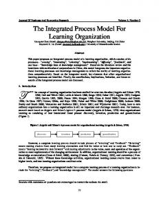
In order to illustrate the importance of our approach for separating process and decision logic, we first present a motivating example. To make our ideas operational, we capture the structural data-flow relations underlying a workflow in a Product Data Model (PDM). The concept of a PDM stems from product based workflow design, a methodology for the radical redesign of workflows [11]. A PDM describes the data elements, data processing steps, and their interrelations that together comprise the data-flow of a process. Figure 1 presents an example PDM. The example depicts the data-flow related to the process that deals with requests for governmental student grants in the Netherlands. 2.1
Product Data Model
A PDM contains a set of data elements, which are depicted as labeled circles. The top element i42, referred to as the root element, corresponds to the total student grant assigned to an applicant. The other data elements in the PDM are relevant to the computation of i42, the ultimate goal of this workflow. A description of all data elements for the example is provided in Table 1. The values for data elements in a specific case are computed by executing operations on data elements. These operations are depicted as black dots in the figure. Each
i42
i43
i46
i44
i47
i45
i40
i21
i41
i27
i38
i23
i33
i48
i20
i26
i39
i37
i32
i35
i36
i30
i29
i28
i25
i24
i19
Fig. 1. Product Data Model of the student grants example Table 1. Description of data elements present in the student grants example ID Description
ID Description
i19 i20 i21 i23 i24 i25 i26 i27 i28 i29 i30 i32 i33 i35
i36 i37 i38 i39 i40 i41 i42 i43 i44 i45 i46 i47 i48
Date of request Birth date of applicant Nationality of applicant Age of applicant Social Security Number of father Reference year for tax authority Social Security Number of mother Applicant has the right to receive grant Income of father of applicant Income of mother of applicant Income of parents of applicant Has requested a supplementary grant Living situation of applicant Max. amt. of supplementary grant
Parental contribution Requested amt. of loan Max. amt. of loan Amt. of supplementary grant assigned Amt. of basic grant assigned Amt. of loan assigned Total amt. of student grant assigned Amt. of tuition credit assigned Max. amt. of credit for tuition fees Tuition fees of educational institution Has requested credit for tuition fees Tuition fees declared by law Kind of education of applicant
operation requires a set of input elements, and produces a single output data element. For example, Figure 1 contains an operation that computes a value for i27 based on the values for i21 and i23. The value for data element i27 forms the basis for the most important decision in the process: it determines if an applicant is eligible to receive a grant.4 For ineligible applicants, i.e. when the value for i27 is negative, the application is directly rejected by executing the left-hand operation that has i42 as its output element. In this case the value for i42 is e 0, because an applicant will not receive any student grant. By contrast, if an applicant is eligible to receive a grant, the right-hand operation to compute i42 must be executed. This operation requires four data elements as input. Namely, the total amount of grant is computed by summing the values for four different sub-grants which eligible applicants may receive: (i) a basic grant (i40), (ii) a supplementary grant (i39), (iii) a student loan (i41), and (iv) any credit for tuition fees (i43). Three of these sub-grants also represent data-driven decisions in the workflow, because their computation follows a data-based choice in the PDM. This is recognizable because these data elements, i.e. i39, i41, and i43, can each be computed by multiple alternative operations. While any eligible applicant will receive the same basic grant, the amounts of the other sub-grants depend on the desire of applicants to receive them, as well as specific assignment criteria.
Assigned amount
Compute tuition fee credit
Determine eligibility
Compute supplementary grant
Compute total grant
Application received
Application handled Compute student loan
Fig. 2. BPMN/DMN model for the student grants example
2.2
BPMN/DMN Model
Due to the high number of atomic data-processing steps involved in a workflow and the complexity of their inter-dependencies, it is not feasible to directly transform a PDM into a process model. For instance, a translation of the example PDM into a process model – using an automated approach from [16] – yields a 4
An applicant must have the Dutch nationality (stored in i21) and may not be older than thirty (i23) in order to be eligible to receive a grant.
process model with 87 activities and over 50 gateways. Process models of such size are difficult to understand and therefore of limited use [8]. To overcome this problem, we first group together elementary data processing steps into larger activities; an act we will refer to as activity composition. Process models based on composed activities are considerably smaller and therefore easier to understand. This is reflected by the process model depicted in Figure 2, which is based on activities specifically designed to emphasize the main flow and decisions in the workflow. The representation of the detailed decision logic underlying this process is outsourced to DMN decision models which we associate with the BPMN model’s activities. Each of the activities in Figure 2 conforms to a fragment of the data-flow structure underlying a workflow, i.e. a set of elementary data processing steps and data elements. The left-hand side of Figure 3, for example, shows the PDM fragment that conforms to the activity “Compute tuition fee credit”. To efficiently represent the decision logic underlying an activity, a PDM fragment can be transformed into a DMN decision model.
i43
Assigned amount (i43) amount table
i27
Maximum amount (i44)
Requested amount (i46)
i45
Tuition fees of institution (i45)
Tuition fees by law (i47)
i48
Kind of education (i48)
i44
i46
i47
Eligibility (i27)
Fig. 3. Transformation of activity “Compute tuition fee credit” to decision model
DMN graphically depicts the inter-relations of the data values relevant to a particular decision in a decision model. We use two types of nodes for the graphical notation: (i) decisions, depicted by rectangles, and (ii) input data, represented by ellipses. The nodes are inter-connected by solid, directed information requirement edges. The right-hand side of Figure 3 provides an example of a decision model related to the computation of the assigned amount of tuition fee credit. The model illustrates that the amount assigned to an applicant depends on the applicant’s eligibility, the requested amount, and a maximum amount based on the tuition fees of the institution. To describe how these data values are actually used when determining the outcome of the decision, DMN uses decision tables. A decision table describes which outcome results from a given set of values for the relevant data elements. Each row in a decision table represents a decision rule, having one or more conditions on the data values and an outcome, i.e.
the conclusion. This conclusion determines the output value of the decision and, thus, also of the workflow activity. For instance, Table 2 shows that tuition fee credit is only assigned to applicants that are eligible and who have specifically requested credit for tuition fees. Table 2. Decision logic to determine tuition fee credit (i43) Eligibility Requested amt. Max. amt. Assigned amt. false — — e0 — e0 — e0 true ex ey min(x, y)
The example presented in this section demonstrates the impact that the separation of concerns paradigm can have on process model design. We transformed the complex data-flow structure underlying a workflow into an understandable BPMN/DMN model. The BPMN model depicts the main process flow, while detailed decision logic is outsourced to separate DMN models. Manually obtaining a BPMN/DMN model from a complex data-flow structure is, however, a tedious and time-consuming endeavor. Most notably because the proper composition of activities requires an in-depth understanding of the elementary data processing steps and their inter-relations. To overcome this problem, Section 3 describes an approach that automatically achieves this.
3
Approach
In this section, we introduce our approach for automatically transforming a PDM into a BPMN model supplemented with DMN decision logic. Because the approach can take any PDM as input, it can be applied to any workflow for which the structure of its underlying data-flow is known. The approach sets out to design process models that emphasize the most important decisions in a workflow, while they outsource decision details to DMN. The remainder of this section describes the three consecutive steps that comprise our approach. In Section 3.1, we first consider the automated grouping of operations into activities. Second, Section 3.2 shows how DMN decision models can be automatically generated for the individual activities. Finally, Section 3.3 covers the conversion of a composed activity design into a BPMN/DMN model. 3.1
Activity Composition
To obtain process models that emphasize the main decisions taken in a workflow, we compose activities that play an important role from a decision-centric viewpoint. We achieve this by designing each activity such that it produces a data value that is important to the workflow’s main process and decision structure.
We identify three classes of data elements that are important to this structure: (i) the root data element, (ii) decision outcomes, and (iii) reference values. The root data element of a PDM should straightforwardly be produced by an activity, because it represents the workflow’s desired end result. Decision outcomes, which we define as those data elements that are created by multiple alternative operations, are also unmistakably important to the decision structure captured in a PDM. For each such data element, we therefore create an activity that determines the outcome of that decision. Lastly, we also define reference values as those data elements that play a role in multiple different decisions. We create separate activities that produce these reference values in order to avoid repeatedly expressing the same decision logic. Consider, for instance, data element i27, an applicant’s eligibility to receive a student grant. This data element is required as input for the computation of all four decision outcomes in the student grant example (i39, i41, i42, and i43). By creating an activity that computes a value for this element, we do not have to express how an applicant’s eligibility is determined for all these individual decisions. Furthermore, due to the involvement of i27 in multiple decisions, it is therefore arguably important to the workflow’s decision structure. Consequently, we deem it worthwhile to emphasize the existence of this data element in the process model. Assuming D as the set of all data elements in a PDM, we define SD as the set of data elements that fall into any of the above-mentioned classes of structurally important data elements. For the student grant example, this thus results in SD = {i27, i39, i41, i42, i43}.
i41
i37
i43
i38
i27
i44
i45
i46
i47
Fig. 4. Operations associated with i27, i41, and i43
Next, for each data element d in SD , we group together a set of operations into an activity that computes d. Similar to earlier activity composition approaches [1,2], we achieve this by recognizing that each operation is directly involved in the computation of exactly one element in SD . For instance, in the fragment of the running example shown in Figure 4, we observe that one operation relates to the computation of i27, four operations to the computation of
i41, and seven to i43. We define the associated data element od of operation o as the sole data element d ∈ SD for which there exists a path p in the PDM from o to d, such that any data element contained in p is not a part of SD . Once the associated data elements have been identified, we compose activities by grouping together those operations with the same od . For data element i43, this for example results in the activity depicted in Figure 3. Section 3.2 describes the subsequent transformation of composed activities into DMN models. 3.2
From Activity to Decision Model
To capture the decision logic underlying activities, we consider both the transformation of an activity into a graphical decision model, as well as the transformation of the actual decision logic into a decision table. As illustrated in Figure 3, the structure of a decision model is closely related to the internal structure of an activity. Both consist of a set of connected nodes leading up to a single root element. We transform a PDM fragment into a decision model as follows. We first create a single decision node that conforms to the root data element of the activity, i.e. the decision outcome. The activity’s input data elements are converted into input data nodes. For each operation, we then draw an information requirement edge from all of its input elements to an (intermediary) decision node. We here avoid creating duplicate edges which occur when different alternative operations use the same input element. Finally, we create and associate decision tables to the decision node. The decision tables linked to decision nodes describe the actual logic applied to determine the outcome of the decision. To transform the decision logic of an activity into a decision table, we translate the execution conditions attached to each operation into a single decision rule. For instance, Table 1 depicts the result of this transformation for the final decision node of the “Compute tuition fee credit” activity, based on the execution conditions specified in [14]. The table shows that an amount is only assigned to applicants that are eligible and who have specifically requested credit for tuition fees. After this transformation, the decision models designed for individual activities can be incorporated into BPMN/DMN models in the form of business rule tasks. Section 3.3 considers the derivation of a process model based on the set of activities comprising the activity design. 3.3
Process Model Derivation
In the final step, we derive a process model based on the composed activity design. Similarly to existing algorithms that transform a PDM into a process model, there is no one size fits all solution for the derivation of a BPMN model based on an activity design. The exact derivation process depends on a modeler’s preferences with respect to a number of design choices, among others, concurrency and execution efficiency [15]. For these reasons, we therefore refrain from introducing a specific process model derivation algorithm. Rather, we describe
the main considerations when turning the activity design of the running example into the process model depicted in Figure 2. The main drivers of process model derivation are the data dependencies that exist between the individual activities. For example, the activity “Determine eligibility” which produces data element i27, must always occur prior to the activity “Compute tuition fee credit” in a process model, because the latter activity requires i27 as input. Data dependencies, similarly, play a crucial role when introducing alternative execution paths. The alternative paths in Figure 2 are, for instance, necessary because the activity “Compute total grant” can be executed based on two sets of input elements, depending on an applicant’s eligibility. Finally, when activities do not have any data inter-dependencies, no restrictions on their execution order are required. In these cases, parallel constructs can be used to allow them to be executed in an arbitrary order, such as seen for the three concurrent activities in the running example. We here note that our automated approach obtains the exact process model depicted in the motivating example. This example illustrates that our approach can find a balance between the details captured in the process model and those captured in its accompanying decision models. To demonstrate the applicability of our approach beyond this example, Section 4 evaluates the approach in other workflow settings.
4
Evaluation
In this section, we evaluate the ability of our approach to provide a balance between details captured in the BPMN model and details captured in its accompanying DMN models. Achieving this balance is crucial, because an approach that fails to omit sufficient details at the process level, results in process models that are too large to be useful. By contrast, if the approach outsources too much detail to its decision models, process models will be too abstract to be informative. Furthermore, the DMN models can simultaneously become so large that also their usefulness is limited. To asses the balance between details captured in a BPMN model and those captured in its DMN models, we compare the size of both types of models. This comparison is based on the premise that size is an important determinant for the amount of details a model contains. We therefore argue that our approach succeeds when both model types are of a comparable size. 4.1
Setting
We evaluate our approach for five cases obtained from literature, four of which represent real-world processes. The five cases, introduced in detail in [2], differ greatly in size and complexity. Table 1 provides additional information on the size of the PDMs. For each case, we compare the size of the generated BPMN model with the average size of its DMN models. For BPMN models, we define size as the number of activities and gateways; for DMN models, we consider their number of data processing steps.
Table 3. Overview of the PDMs included in the evaluation ID Description Operations Data elements Decisions 1 Student grant (NL) 32 27 4 2 Bicycle manufacturing 36 29 3 3 Student grant (US) 48 45 3 4 Unemployment benefits 51 42 2 5 Fireworks license 81 46 4
4.2
Results
Figure 5 depicts the sizes of a case’s original PDM, the generated BPMN model, and the decision models it contains. For each of the five cases it is clear that the size of all generated models is greatly reduced in comparison to the original PDM. Furthermore, it can be observed that the size of the BPMN models is generally well-comparable to the size of its DMN models. The largest differences are found for cases 2 and 3. For the former case, the average size of the decision models is smaller than the one of the process model, because the generated process model includes a number of relatively small activities. That is because the process contains several different routing paths. The existence of these paths requires more process logic than decision logic when modeling the workflow. By contrast, the decision models in case 3 are on average larger than the process model for this case. We argue that also this imbalance is acceptable, because the difference results from the existence of a small number of complex decisions that take up to 25 different input elements. For the other cases, the size differences are even smaller and the results thus imply that the size of the models is overall well-balanced.
Number of tasks 90 80 70 60 50 40 30 20 10 0
Case 1
Case 2
Case 3 PDM
BPMN model
Case 4
Case 5
DMN models (avg.)
Fig. 5. Comparison of model sizes between a PDM, the generated BPMN model, and its largest DMN model
While these are just preliminary results, the evaluation indicates that our proposed approach distributes the complexity of a PDM over a BPMN model and its DMN models in a relatively even manner. As a result, the generated BPMN/DMN models provide a balance between process logic captured in the process model and detailed decision logic contained in its individual activities.
5
Related Work
The work presented in this paper mainly relates to process model abstraction and the separation of decision from process logic. The goal of process model abstraction approaches is to group process model elements in an adequate way to increase understandability or to gain a different perspective. Existing approaches mainly focus either on structural properties, e.g. [10,13], or on semantic aspects such as activity labels [12]. The benefits of separating decision logic from process logic have been recognized by academic as well as rather practitioner-oriented contributions [5,7,17]. However, only recently researchers investigated how decision logic can be extracted from existing business process models. In [3], Batoulis et al. identify a number of control-flow patterns that indicate the presence of decision logic. Based on this analysis, they introduce a semi-automated approach to extract DMN models from BPMN process models. While our approach pursues a similar goal, we use PDMs as input. Hence, we have to deal with different challenges as, for example, activity composition.
6
Conclusions
This paper presented an approach to automatically derive a BPMN/DMN model based on the data-structure underlying a workflow. Our approach creates process models that emphasize the most important decisions in a workflow, while outsourcing the representation of the detailed decision logic to dedicated decision models. Due to its automated nature, the approach overcomes the time and effort involved in the manual transformation from complex data-flow structure to BPMN/DMN model. A preliminary evaluation furthermore revealed that the approach successfully provides a balance between the details captured in a BPMN model, and those captured in its DMN decision models. In future work, we plan to extend the evaluation in order to further assess the effectiveness of our approach. For instance, we consider comparing the automatically generated process models to ones that have been manually created by modeling experts. The approach itself can furthermore be extended by incorporating other perspectives beyond the structural data-flow relations, e.g. by taking different organizational actors into account that are involved in the workflow execution.
References 1. Van der Aa, H., Reijers, H.A., Vanderfeesten, I.: Composing workflow activities on the basis of data-flow structures. In: Business Process Management, pp. 275–282. Springer (2013) 2. Van der Aa, H., Reijers, H.A., Vanderfeesten, I.: Designing like a pro: The automated composition of workflow activities. Computers in industry (2015 (in press)) 3. Batoulis, K., Meyer, A., Bazhenova, E., Decker, G., Weske, M.: Extracting decision logic from process models. In: Advanced Information Systems Engineering. pp. 349–366. Springer (2015) 4. Davies, I., Green, P., Rosemann, M., Indulska, M., Gallo, S.: How do practitioners use conceptual modeling in practice? Data & Knowledge Engineering 58(3), 358– 380 (2006) 5. Debevoise, T., Taylor, J., Geneva, R., Sinur, J.: The Microguide to Process and Decision Modeling in Bpmn/Dmn: Building More Effective Processes by Integrating Process Modeling with Decision Modeling (2014) 6. Goedertier, S., Vanthienen, J., Caron, F.: Declarative business process modelling: principles and modelling languages. Enterprise Information Systems 9(2), 161–185 (2015) 7. Kluza, K., Kaczor, K., Nalepa, G.: Integration of business processes with visual decision modeling. presentation of the hades toolchain. In: Fournier, F., Mendling, J. (eds.) Business Process Management Workshops, vol. 202, pp. 504–515 (2015) 8. Mendling, J., Reijers, H.A., Cardoso, J.: What makes process models understandable? In: Business Process Management, pp. 48–63. Springer (2007) 9. OMG: Decision Model and Notation (DMN). FTF Beta 1 (2015) 10. Polyvyanyy, A., Smirnov, S., Weske, M.: The triconnected abstraction of process models. In: Dayal, U., Eder, J., Koehler, J., Reijers, H. (eds.) Business Process Management, Lecture Notes in Computer Science, vol. 5701, pp. 229–244 (2009) 11. Reijers, H.A., Limam, S., Aalst, W.v.d.: Product-based workflow design. Journal of Management Information Systems 20(1), 229–262 (2003) 12. Smirnov, S., Reijers, H.A., Weske, M.: A semantic approach for business process model abstraction. In: Advanced Information Systems Engineering. pp. 497–511. Springer (2011) 13. Smirnov, S., Weidlich, M., Mendling, J.: Business process model abstraction based on behavioral profiles. In: Service-Oriented Computing, pp. 1–16. Springer (2010) 14. Vanderfeesten, I.: Product-Based Design and Support of Workflow Processes. Ph.D. thesis, Eindhoven University of Technology (2009) 15. Vanderfeesten, I., Reijers, H.A., Aalst, W.v.d.: Case handling systems as product based workflow design support. Enterprise Information Systems pp. 187–198 (2009) 16. Vanderfeesten, I., Reijers, H.A., Aalst, W.v.d., Vogelaar, J.: Automatic support for product based workflow design: generation of process models from a product data model. In: OTM 2010 Workshops. pp. 665–674. Springer (2010) 17. Von Halle, B., Goldberg, L.: The Decision Model: A Business Logic Framework Linking Business and Technology. CRC Press (2009)