Integrated TiO2 resonators for visible photonics Jennifer T. Choy1,∗ , Jonathan D. B. Bradley1 , Parag B. Deotare1 , Ian B. Burgess1 , Christopher C. Evans1 , Eric Mazur1,2 , and Marko Lonˇ car1 1
School of Engineering and Applied Sciences, Harvard University, Cambridge, MA, 02138 USA 2 Department of Physics, Harvard University, Cambridge, MA, 02138 USA ∗ Corresponding author:
[email protected]
arXiv:1111.3545v1 [physics.optics] 15 Nov 2011
Compiled November 16, 2011 We demonstrate waveguide-coupled titanium dioxide (TiO2 ) racetrack resonators with loaded quality factors of 2.2 × 10⁴ for the visible wavelengths. The structures were fabricated in sputtered TiO2 thin films on oxidized silicon substrates using standard top-down nanofabrication techniques, and passively probed in transmission measurements using a tunable red laser. Devices based on this material could serve as integrated optical elec 2011 Optical Society of America ments as well as passive platforms for coupling to visible quantum emitters. OCIS codes: 130.3120, 230.5750.
Optical microresonators are ubiquitous components in optical telecommunication systems and provide a compact and efficient means for studying cavity quantum electrodynamics [1]. The integration of microresonators into classical and quantum networks relies on materials that support high quality optical components on a chip-scale [2, 3]. In the growing field of quantum photonics, single photon sources such as solid-state color centers [4] and emitters [5, 6] operate primarily in the visible wavelengths. Therefore, the development of a chip-scale platform for the visible is a critical step towards the realization of quantum communication networks, and can be beneficial to classical applications such as light generation and on-chip sensing. While gallium phosphide [7], silicon nitride [3, 8, 9], silicon dioxide [10], and diamond [11], are all promising materials in this regard, certain challenges remain, including intrinsic luminescence [8], difficulty of generating thin membranes with low optical loss [12], poor refractive index contrast with the surrounding medium [10], and lower tolerance for fabrication imperfections due to inherently smaller characterisitic lengths. Titanium dioxide (TiO2 ) can be added to the family of viable integrated visible photonics platforms. It is a widebandgap semiconductor (with a bandgap energy between 3 – 3.5 eV, depending on the crystalline phase [13]) with a moderately high index for the visible wavelengths (n ≈ 2.4) and a wide transparency window from the near UV to the IR. It is also naturally abundant and is compatible with a host of conventional growth techniques. While the optical properties of TiO2 have been exploited in three-dimensional photonic crystals [14], gratings [15], and waveguides [16, 17], planar resonator structures in this material had yet to be demonstrated. Here we show scalable and integrable TiO2 racetrack resonators, having loaded quality factors (Q) on the order of 104 with efficient coupling to a feeding waveguide. Amorphous TiO2 thin films of thickness 170 nm have been deposited on oxidized silicon substrates using RF sputtering of a Ti target in an O2 /Ar environment [17].
Prism coupling experiments [17] indicated that the deposited films have a refractive index of 2.36 at 633 nm and propagation losses as low as 2 dB/cm. These losses suggest that the material-limited Q for optical cavities is Qmat ≈ 5 × 10⁵ . The waveguide-coupled racetrack resonators used in this experiment were designed to minimize bending losses (by making bending radii R = 30 µm), so that additional losses would be mostly due to coupling and scattering from structural imperfections resulting from fabrication. Additionally, the waveguideresonator separation g and coupling length L were chosen to ensure efficient transfer of light signal between the cavity and waveguide [18].
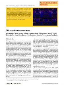
Fig. 1. (a) Optical image of a set of TiO2 waveguideracetrack devices integrated with polymer pads for coupling light on- and off-chip. Output from a HeNe laser (632nm) was fed through the middle device and coupled to both the waveguide and racetrack resonator. SEM images of (b) a TiO2 waveguide-resonator, (c) its 100-nm coupling region, and (d) etch profile taken at a 45 degree tilt. Cross sections of the fabricated waveguide/resonator with superimposed electric field profiles of the (e) TE and (f) TM modes as calculated by FEM. Propagation is in the x direction. 1
We realized the designed structures using conventional top-down fabrication techniques which include electron beam lithography on a positive electron beam resist (ZEP 520A), electron beam evaporation of a chromium (Cr) mask layer, metal liftoff, and reactive ion etching in a CF4 /H2 environment at a chamber pressure of 5 mTorr. The recipe has an etch rate of approximately 60 nm/min and leads to slightly slanted sidewalls with an angle of 75◦ [17]. The Cr etch mask was subsequently removed by a Cr etchant and polymer pads (SU-8 2002, with cross-sections 3 µm × 3 µm) were written using electron beam lithography [19]. These pads overlap the tapered region of the waveguides and extend to the edge of the chip (Fig. 1a). The edges of the polymer waveguides were then cleaved to facilitate in- and out-coupling of light. The resulting resonators have smooth sidewalls, with gaps of roughly 100 nm in the coupling region (Fig. 1b-d). We simulated the mode profiles of the fabricated TiO2 waveguides (Fig. 1e-f) using the finite element method (FEM). From SEM imaging, the waveguides have a width of 250 nm on their top facets. The etch depth is roughly 150 nm, so there is a 20-nm thick pedestal TiO2 layer above the oxide film. These dimensions support one fundamental mode in each of the transverse-electric (TE) and transverse-magnetic (TM) polarizations with respective effective indices of 1.80 and 1.61 at a wavelength of 630 nm. The resonators were characterized by transmission measurements using a tunable red laser with a scanning range of 634.4 – 639.6 nm. The output of the laser was coupled to a single mode, tapered lens fiber that was oriented such that the input signal into the sample was fixed to either the TE or TM polarization. Light with a spot size of 0.8 µm in diameter was focused onto the facet of the polymer pad by the tapered lens fiber and transmitted into the waveguide-resonator device. The output was coupled through a polymer pad on the opposite end of the chip and collected by another tapered lens fiber that was connected to a high speed silicon detector. The resonator transmission spectra are shown in Fig. 2. The transmission spectra have periodicallyspaced dips corresponding to whispering-gallery modes (WGM) with either the TE (Fig. 2a) or TM (Fig. 2b) poλ , larization. The loaded quality factors (Qloaded = FWHM where λ is the cavity resonance wavelength and FWHM is the full-width at half maximum at resonance) were extracted by fitting the transmission dips to the Fano model [20]. The fits yielded linewidths as narrow as 0.028 nm and 0.11 nm for the TE and TM polarizations (respectively) near λ = 635 nm, corresponding to respective Q values of 2.2 × 10⁴ and 5.6 × 10³ . The observed transmission drops are as large as 96%, indicating that the resonators are nearly critically coupled. The transmission properties of a waveguide-coupled racetrack resonator have been well-described elsewhere [18, 21]. The resonance condition is given by n(2πR + 2L) = mλ, where m is the integer mode num-
Fig. 2. (a) TE-polarized transmission as a function of wavelength for a racetrack resonator with R = 30 µm and L = 15 µm. Inset: cavity mode at 634.94 nm, along with a fit to the Fano model (red). The fitted linewidth is 0.028 nm, corresponding to a Q of 22400. (b) TMpolarized transmission as a function of wavelength for the same resonator. Inset: cavity mode at 636.36 nm, with a fitted linewidth of 0.11nm and corresponding Q of 5629. ber and n is the wavelength-dependent refractive index. Here, we have assumed that the differences between the effective indices in the coupling, waveguide, and bending regions are negligible, which was confirmed by FEM calculations. The free spectral range (FSR) between consecutive modes m and m+1 in such a system is described by dn λ2 FSR × (n − )≈ . (1) dλ 2πR + 2L The quantity n − λ dn dλ is denoted as the group index ng and takes into account dispersion in the system [22]. We used the Sellmeier coefficients obtained from spectroscopic ellipsometry measurements on our TiO2 films to determine the wavelength-dependent index (nmat ). The first order effective index (nef f ) and group index (ng ) were then computed and are shown in Fig. 3. In the visible wavelengths, ng in TiO2 waveguides can be significantly larger than nef f (difference of approximately 57% for the TE mode and 70% for the TM mode). The greater difference observed in the TM polarization is due to larger waveguide dispersion, which can be estimated by calculation of the group index ng,w of the given waveg2
partment of Energy, Office of Science, Office of Basic Energy Sciences under Award Number DE-SC0001088. The devices were fabricated at CNS at Harvard University. We thank Q. Quan, B. Hausmann, M. McCutcheon, M. Khan, F. Parsy, L. Xie, G. Akselrod, V. Bulovic, M. Pollnau, R. Jensen, L. Marshall, and M. Bawendi for useful discussions and help with the project. J.T.C acknowledges support from NSF GRFP. References 1. K. Vahala, Nature, 424, 839–846 (2003). 2. M. Lipson, J. Lightwave Technol., 23, 4222–4238 (2005). 3. E.S. Hosseini, S. Yegnanarayanan, A.H. Atabaki, M. Soltani, and A. Adibi, Opt. Express, 17, 14543–14551 (2009). 4. C. Kurtsiefer, S. Meyer, P. Zarda, and H. Weinfurter, Phys. Rev. Lett., 85, 290–293 (2000). 5. C. B. Murray, C. R. Kagan, and M. G. Bawendi, Annu Rev Mater Sci, 30, 545–610 (2000). 6. B. Lounis and W. E. Moerner, Nature, 407, 491–493 (2000). 7. K. Rivoire, A. Faraon, and J. Vuckovic, Appl. Phys. Lett., 93, 063103 (2008). 8. M. Barth, N. Nsse, J. Stingl, B. Lchel, and O. Benson, Appl. Phys. Lett., 93, 021112 (2008). 9. M. Khan, T.M. Babinec, M. W. McCutcheon, P.B. Deotare, and M. Loncar, Opt. Lett., 36, 421 (2011). 10. Y. Gong and J. Vuckovic, Appl. Phys. Lett., 96, 031107 (2010). 11. A. Faraon, P.E. Barclay, C. Santori, K.-M.C. Fu, and R.G. Beausoleil, Nature Photon., 5, 301–305 (2011). 12. C. F. Wang, R. Hanson, D. D. Awschalom, E. L. Hu, T. Feygelson, J. Yang, and J. E. Butler, Appl. Phys. Lett., 91, 201112 (2007). 13. S. A. Campbell, H.-S. Kim, D. C. Gilmer, B. He, T. Ma, and W. L. Gladfelter, IBM J. Res. Develop., 43, 383–392 (1999). 14. G. Subramania, Y.-J. Lee, A.J. Fischer, and D.D. Koleske, Adv. Mat., 21, 1–5 (2009). 15. T. Alasaarela and T. Saastamoinen and J. Hiltunen and A. Saynatjoki and A. Tervonen and P. Stenberg and M. Kuittinen and S. Honkanen, Appl. Opt., 49, 4321–4325 (2010). 16. M. Furuhashi, M. Fujiwara, T. Ohshiro, M. Tsutsui, K. Matsubara, M. Taniguchi, S. Takeuchi, and T. Kawai, AIP Advances,1, 032102 (2011). 17. J.D.B. Bradley et. al., in preparation. 18. M.K. Chin, C. Youtsey, W. Zhao, T. Pierson, Z. Ren, S.L. Wu, L. Wang, Y.G. Zhao, and S.T. Ho, IEEE Photonic. Tech. L., 11, 1620–1622 (1999). 19. Q. Quan, P.B. Deotare, and M. Loncar, Appl. Phys. Lett., 96, 203102 (2010). 20. S. Fan, W. Suh, and J. D. Joannopoulos, J. Opt. Soc. Am. A, 20, 569–572 (2003). 21. L. Zhou and A. Poon, Opt. Express, 15, 9194–9204 (2007). 22. A. Guarino, G. Poberaj, D. Rezzonico, R. Degl’Innocenti, and P. Gunter, arXiv:0705.2392 (2007). 23. K. Preston, B. Schmidt, and M. Lipson, Opt. Express, 15, 17283–17290 (2007).
Fig. 3. Calculated effective (nef f ) and group (ng ) indices as a function of wavelength for the TE and TM-polarized waveguide modes. Contributions to the difference between nef f and ng include dispersions in the material (nmat ) and waveguide, which can be inferred by calculating ng using a fixed nmat of 2.4 (ng,w ).
uide without considering the wavelength-dependence in nmat . The large discrepancy between ng and nef f can thus be attributed to both waveguide and material dispersions, although the contribution from the latter decreases with increasing wavelengths, as indicated by the diminishing difference between the group index with and without material dispersion (ng and ng,w , respectively). Dispersion must therefore be considered when designing optical components in TiO2 and can be exploited to generate small FSRs without significantly increasing the device footprint. The calculated ng values are in good agreement with the experimentally obtained number, in which an FSR of 0.64 nm (Fig. 2a) corresponds to a group index of 2.92 in the 635 nm to 640 nm range in the TE polarization. Finally, the propagation loss in a critically-coupled πng resonator can be estimated using αr = λQloaded [23]. Based on a TE-polarized mode with a Q of 22400 and transmission drop of 92% (inset of Fig. 2a), the corresponding propagation loss is 28 dB/cm. The deviation from the planar loss value can be attributed to scattering losses from surface roughness introduced by the fabrication process, which might be reduced by using a top-cladding material. We have demonstrated planar resonators in TiO2 thin films for visible light operation with efficient coupling to waveguides for delivering light on- and off-chip. The methods and devices shown here could help advance the TiO2 material platform towards integration with active emitters for novel and integrated classical and nonclassical light sources and on-chip sensing. The research described in this paper was supported by the NSF under contract ECCS-0901469 and based upon work supported as part of the Center for Excitonics, an Energy Frontier Research Center funded by the U.S. De3
References
ration. 18. M.K. Chin, C. Youtsey, W. Zhao, T. Pierson, Z. Ren, S.L. Wu, L. Wang, Y.G. Zhao, and S.T. Ho, “GaAs microcavity channel-dropping filter based on a race-track resonator,” IEEE Photonic. Tech. L., 11, 1620–1622 (1999). 19. Q. Quan, P.B. Deotare, and M. Loncar, “Photonic crystal nanobeam cavity strongly coupled to the feeding waveguide,” Appl. Phys. Lett., 96, 203102 (2010). 20. S. Fan, W. Suh, and J. D. Joannopoulos, “Temporal coupled-mode theory for the Fano resonance in optical resonators,” J. Opt. Soc. Am. A, 20, 569–572 (2003). 21. L. Zhou and A. Poon, “Electrically reconfigurable silicon microring resonator-based filter with waveguide-coupled feedback,” Opt. Express, 15, 9194–9204 (2007). 22. A. Guarino, G. Poberaj, D. Rezzonico, R. Degl’Innocenti, and P. Gunter, “Electro-optically tunable microring resonators in lithium niobate,” arXiv:0705.2392 (2007). 23. K. Preston, B. Schmidt, and M. Lipson, “Polysilicon photonic resonators for large-scale 3D integration of optical networks,” Opt. Express, 15, 17283–17290 (2007).
1. K. Vahala, “Optical microcavities,” Nature, 424, 839– 846 (2003). 2. M. Lipson, “Guiding, modulating, and emitting light on silicon - challenges and opportunities,” J. Lightwave Technol., 23, 4222–4238 (2005). 3. E.S. Hosseini, S. Yegnanarayanan, A.H. Atabaki, M. Soltani, and A. Adibi, “High quality planar silicon nitride microdisk resonators for integrated photonics in the visible wavelength range,” Opt. Express, 17, 14543– 14551 (2009). 4. C. Kurtsiefer, S. Meyer, P. Zarda, and H. Weinfurter, “Stable solid-state source of single photons,” Phys. Rev. Lett., 85, 290–293 (2000). 5. C. B. Murray, C. R. Kagan, and M. G. Bawendi, “Synthesis and characterization of monodisperse nanocrystals and close-packed nanocrystal assemblies,” Annu Rev Mater Sci, 30, 545–610 (2000). 6. B. Lounis and W. E. Moerner, “Single photons on demand from a single molecule at room temperature,” Nature, 407, 491–493 (2000). 7. K. Rivoire, A. Faraon, and J. Vuckovic, “Gallium phosphide photonic crystal nanocavities in the visible,” Appl. Phys. Lett., 93, 063103 (2008). 8. M. Barth, N. Nsse, J. Stingl, B. Lchel, and O. Benson, “Emission properties of high-Q silicon nitride photonic crystal heterostructure cavities,” Appl. Phys. Lett., 93, 021112 (2008). 9. M. Khan, T.M. Babinec, M. W. McCutcheon, P.B. Deotare, and M. Loncar, “Fabrication and characterization of high-quality-factor silicon nitride nanobeam cavities,” Opt. Lett., 36, 421 (2011). 10. Y. Gong and J. Vuckovic, “Photonic crystal cavities in silicon dioxide,” Appl. Phys. Lett., 96, 031107 (2010). 11. A. Faraon, P.E. Barclay, C. Santori, K.-M.C. Fu, and R.G. Beausoleil, “Resonant enhancement of the zerophonon emission from a colour centre in a diamond cavity,” Nature Photon., 5, 301–305 (2011). 12. C. F. Wang, R. Hanson, D. D. Awschalom, E. L. Hu, T. Feygelson, J. Yang, and J. E. Butler, “Fabrication and characterization of two-dimensional photonic crystal microcavities in nanocrystalline diamond,” Appl. Phys. Lett., 91, 201112 (2007). 13. S. A. Campbell, H.-S. Kim, D. C. Gilmer, B. He, T. Ma, and W. L. Gladfelter, “Titanium dioxide (TiO2 )based gate insulators, IBM J. Res. Develop., 43, 383– 392 (1999). 14. G. Subramania, Y.-J. Lee, A.J. Fischer, and D.D. Koleske, “Log-Pile TiO2 photonic crystal for light control at near-UV and visible Wavelengths,” Adv. Mat., 21, 1–5 (2009). 15. T. Alasaarela and T. Saastamoinen and J. Hiltunen and A. Saynatjoki and A. Tervonen and P. Stenberg and M. Kuittinen and S. Honkanen, “Atomic layer deposited titanium dioxide and its application in resonant waveguide grating,” Appl. Opt., 49, 4321–4325 (2010). 16. M. Furuhashi, M. Fujiwara, T. Ohshiro, M. Tsutsui, K. Matsubara, M. Taniguchi, S. Takeuchi, and T. Kawai, “Development of microfabricated TiO2 channel waveguides,” AIP Advances,1, 032102 (2011). 17. J.D.B. Bradley et. al., “Submicrometer-width amorphous and polycrystalline TiO2 waveguides,” in prepa-
4