.
A I
I N
P O W E R
S Y S T E M S
Integrating AI Applications in an Energy Management System Jeffrey J. Bann, Guillermo D. Irisarri, and Sasan Mokhtari, Siemens Power Transmission and Distribution, LLC Daniel S. Kirschen, University of Manchester Institute of Science and Technology Bradley N. Miller, Net Perceptions
D
ESPITE THE OVERWHELMING satisfaction utilities report in implementing pioneer expert systems in energy-management systems, the number of actual implementations of such systems in control centers remains quite small compared to the number of systems successfully demonstrated in prototype form.1–3 This discrepancy suggests that utilities have unanswered concerns about the cost and difficulty of integrating expert systems into an EMS. Applications developers must address these concerns before this technology finds a wider acceptance in power-system operation. As part of that effort, we first needed to determine why integrating an expert system or other type of AI application in an EMS is more complex and costly than adding a conventional advanced application program. Based on this analysis, we then defined the interfaces needed to achieve an effective integration. This groundwork led us to believe that AI applications should not be integrated directly into the EMS. Rather, they should plug into an AI environment that supports the necessary interfaces with the EMS and provides common services to the applications. We have designed and implemented such an environment, which currently supports three distinct AI applications—intelligent NOVEMBER/DECEMBER 1997
TO EFFECTIVELY INTEGRATE EXPERT SYSTEM APPLICATIONS IN AN ENERGY-MANAGEMENT SYSTEM, THE AUTHORS CREATED AN ENVIRONMENT THAT SUPPORTS ALL THE INTERFACES BETWEEN THE AI APPLICATIONS AND THE EMS.
THIS ENVIRONMENT ALSO MAINTAINS A MODEL OF THE POWER SYSTEM COMMON TO ALL THE AI APPLICATIONS. WITH THIS ENVIRONMENT IN PLACE, USERS CAN EASILY PLUG AI APPLICATIONS INTO THE EMS.
alarm processing, fault diagnosis, and power-system restoration. To illustrate the benefits of this approach, this article presents case studies based on implementations of this environment in three different EMS architectures.
Integration issues Important integration issues in developing this architecture are those involving the power-system model and the interface with other EMS subsystems. 0885-9000/97/$10.00 © 1997 IEEE
Power-system model. At the heart of most computer programs lies a model of the problem domain. This model defines the entities that the program is designed to handle and describes their characteristics and state. For nontrivial software systems, good practice dictates that designers functionally separate the model from the applications that analyze or modify this model. Users can easily extract such explicit models and store them in databases. A supervisory control and data-acquisition (Scada) system requires a model of the pieces of equipment used to monitor and con53
.
trol the power system. The Scada model is suitable for the data-acquisition and supervisory tasks. When designers add security and scheduling applications to Scada systems to create the EMS, they also add a model of the power devices to the Scada model. Although these two models describe different aspects of the same entity (the power system), designers often keep them separate for practical and historical reasons. AI applications, such as conventional advanced applications (dispatcher power flow, security analysis, and optimum power flow), need a model of the power system. The advanced AI applications can usually extract most of the information they need from the model. However, this model is usually organized in indexed tables—a type of data structure that facilitates the development of highperformance algorithmic programs, but that is impractical for AI applications because they are usually built using specialized tools or shells. The shells will only fully realize their power, flexibility, and performance capabilities if the data is organized in spe-
cialized data structures within the shell. AI applications therefore require their own model of the power system. Adding another power-system model to the EMS involves implementing a mechanism to populate the model from a database. The new power-system model will also need to initialize the dynamic attributes of this model from the real-time data and update these attributes when a change occurs in the power system. System developers could argue that the AI shells create the need for a separate model and that creating a specialized AI shell working directly from the conventional data structures would solve this and other problems. While theoretically possible, such a tool would not have the flexibility and power of general-purpose tools and would seriously hamper the development of flexible AI applications. Because no such tool is commercially available, it would have to be custom made and proprietary. Developing such a tool would require a large investment of resources, and its adoption would run counter
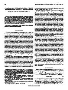
Scada Decision layer
Applications layer Symbolic applications
Numeric applications
Scada
Data-access layer
to the current philosophy of EMS design practices. Interface with other EMS subsystems. As their name suggests, shells tend to isolate the AI applications from the rest of the EMS. While current commercial shells are considerably more open than tools that were available a few years ago, integrating the AI applications with the other EMS subsystems still requires the construction of a special interface. In particular, this interface should support the following interactions: • Real-time data. AI applications must base their reasoning on the actual state of the power system. Consequently, they must know about significant events taking place in the power system and be able to obtain the value of specific telemetered data. • Relational database. Most modern EMSs include a relational database for storing the primitive data description of the system and historical data. AI applications must access this database to build their model and, if necessary, store some of their results. • User interface. The EMS’s standard user interface should display conclusions and other results produced by the AI application. This requirement is particularly important if one-line diagrams (which show detailed information about substations) and other graphical displays present these results. • Numerical applications. The conventional numerical applications of an EMS (such as power flow and security analysis) can provide information that greatly enhances the power of AI applications. AI applications therefore should be able to set up and run numerical applications and analyze their results. • Supervisory control. In some situations, users might want to let an AI application issue commands through the supervisorycontrol subsystem. • Configuration control. It should be possible to start up, shut down, and check the status of the AI applications through the standard configuration-control mechanisms.
Database layer
Figure 1. ODE architecture. 54
Reasons for creating an AI environment. Creating a power-system model and a set of interfaces for each AI application considerably increases the development and integration costs of these applications. To reduce IEEE EXPERT
.
these costs, we considered creating an environment where we could easily plug in various AI applications. This environment would provide all the interfaces with the EMS required by the AI applications and would also support a model of the power system shared by all the AI applications. Because the various AI applications would reside in the same environment, we could easily set up interapplication communication mechanisms. This environment would facilitate the development of AI applications capable of collaborating on the solution of related problems. The Operator Decision Environment that we have designed supports these modeling and interfacing requirements.
ODE design The ODE architecture follows a layered concept similar to the one used for specifying computer systems. As Figure 1 shows, the ODE architecture contains four layers: • The database layer contains all the static data, knowledge bases, and information needed to support the reasoning and decision-making activities at the higher layers. • The data-access layer provides the mechanisms for accessing information from the data layer. It also provides a representation media for data and knowledge used by the various AI applications residing in the upper layers. The data-access layer also includes interfaces to the EMS for exchange of data with the various software components comprising the traditional side of the EMS (the Scada system, in particular). • The applications layer contains all the AI and expert system applications, as well as the various AI and expert system tools used with these applications. The tools considered here are tools that support reasoning and problem solving in expert systems and, more generally, in AI problem solving. These tools work in applications ranging from diagnosis, to planning, to design. • The decision layer consists of a knowledge-based component that oversees the orchestrated execution of all the tools and applications in the application layer and their relationship to the numerically intensive applications. The decision layer, like the data-access layer, connects to the NOVEMBER/DECEMBER 1997
EMS to access and provide the required decision and control information for reasoning tasks. In the early design stages, we decided that the ODE should facilitate the integration of the applications but should not overly constrain their development. Each application should capitalize on the services provided by the ODE without having to completely fold into the ODE. This decision to preserve the independence and modularity of the applications led quite naturally to the adoption of a client-server implementation architecture. Figure 2 illustrates this architecture. The client-server architecture contains elements of all four architectural layers. ODE consists of three types of independent processes: • Data server. The OdeRT process is the heart of the system. It supports the model of the power system and acts as a focal point for communications among the applications and with the rest of the EMS.
FD
• Interfaces. OdePOP creates the model of the power system, and OdeCOM supports all communications between ODE and the rest of the EMS. • Applications. Within ODE, our design integrates processes responsible for intelligent alarm processing (IAP), fault diagnosis (FD), and restoration assistance (RA).3–5 We are currently integrating other applications (such as a switching assistant) into ODE. All these applications are written using the Snap software-development tool and communicate through the interprocess communication facility provided by Snap. 6 Each application can operate independently and asynchronously. Furthermore, each can reside on a different workstation and communicate using the interprocess communication support of the EMS local area network. Snap’s interprocess communication facility (the shared information base, or SIB) lets processes share pertinent objects. Using object-oriented programming terminology,
RA
Other apps
IAP ODE applications OdeRT ODE interfaces
ODE server
OdePOP
OdeCOM
EMS message bus Primitive data
FD EMS IAP ODE RA
Fault-diagnosis system Energy management system Intelligent alarm processing Operator decision environment Restoration assistance
Figure 2. Client-server Implementation architecture. 55
.
Equipment
Node
Load
Injector
Inductor
AC line
Capacitor
Operator
Bipole
Switch
Transformer
Series device
Phase shifter
Figure 3. Inheritance hierarchy of the ODE power-system model.
Base_switch • type • position Switch • relays (FD)
Switch • operability (RA)
Switch (IAP)
Figure 4. Diagram illustrating how the class Switch is defined for the FD, RA, and IAP applications and how these classes inherit a common class called Base_Switch.
these objects include both classes and class members, and single attributes from particular classes. The developer declares which classes and attributes can be shared with other processes. A SIB connection defines which classes and attributes the two processes will actually share. At runtime, once the SIB connection has been established, both the server and client processes see the same objects. In addition, all the modifications made to these objects by one process are automatically reflected in the objects seen by the other process. Snap is just one tool that might be used to build an environment such as ODE. Important features of Snap that have facilitated the development of ODE include • direct support for the client-server architecture through the use of the SIB, • ease of integration with external software through the use of well-defined application program interfaces, • built-in interfaces to commercial databases, • support for the object-oriented programming paradigm, and • direct support for rule-based programming. 56
The power-system model. Our system’s ability to share classes lets us implement a model of the power system that is common to all the AI applications integrated into ODE. This model is defined within the OdeRT process, which loads its static characteristics upon startup, initializes the dynamic attributes to reflect the status of the power system, and updates this model every time a significant event occurs in the power system. Each application process accesses this model by establishing a SIB connection with OdeRT. Figure 3 shows a portion of the inheritance hierarchy of the power system’s common model. The hierarchy shown here is a typical inheritance hierarchy or semantic net. Semantic nets can describe both structure and behavior in AI applications. The relationship from a child to a parent object is of the type Is-A structure—for example, an Inductor Is-A type of Injector. In this hierarchy, an inductor’s behavior, for example, arises from the inherited behavior of its ancestors, together with the specific behavior described in the object itself. In keeping with the desire to preserve the independence of the applications, the common model contains only the classes and attributes that are needed by more than one application. Each application can augment the common model to include the characteristics of the power system it needs to model, and that are not of interest to any other application. Figure 4 illustrates this principle for the class Switch. The class Base_Switch defines the switching devices for the common model. Suppose that this definition requires only two attributes: the type of the switch (breaker or disconnect, for example) and the position of the switch (open or closed). The models define a separate class Switch for each of the three applications. Each of them inherits the attrib-
utes of the class Base_Switch and augments it for its own purposes. The fault-diagnosis system (FD) adds an attribute that indicates the relays that can activate this switch. The restoration-assistance application (RA) adds an attribute to keep track of whether a particular switch can be operated. Finally, the intelligent alarm-processing application (IAP) need not add any attribute to the basic definition of a switch. All three applications will see the same switches but will only have access to the attributes defined in the class Base_Switch and those defined in their own Switch class. For example, RA does not know which relays activate a particular switch. This approach allows the developer of each application to add attributes to classes without creating conflicts with other applications or forcing a recompilation of the entire system. Instantiating and initializing the model. Manually maintaining a power-system model to accommodate new equipment is a timeconsuming but unavoidable task. Utilities minimize the expense associated with this maintenance by consolidating all their powersystem data in one primitive model. This primitive model usually resides in a relational database and is the only model that is maintained manually. All other models derive from this model. In particular, the data-maintenance system will instantiate the classes of the ODE model that describe the power system’s physical components and populate them from this primitive model. Whenever this primitive model changes significantly, the batch process OdePOP (Figure 2) activates. This process establishes a connection with the database containing the primitive model and creates a new object-oriented model of the power system. More precisely, OdePOP instantiates the classes that correspond to the physical components and creates links among the members of these classes to reflect the power system’s structure. Because the creation of this model is a relatively slow process, OdePOP saves a description of the model in specially formatted files that OdeRT can load quickly every time ODE and its applications start up for online use. Once OdeRT has loaded the model created by OdePOP, it brings this model to life by adding status information, such as the position of switching devices and the energization of generators. This initialization data comes from the EMS’s online database through the OdeCOM process. Using the IEEE EXPERT
.
IEEE
Call for Articles Applications of Intelligent Information Retrieval Guest Editors: Yiming Yang, Carnegie Mellon University Jan Pedersen, Verity Inc. Intelligent information retrieval—the problem of delivering truly relevant documents matching user needs—has become increasingly central in recent years thanks to the dramatically growing amounts of online textual data. Addressing this problem calls for synergy between information retrieval and artificial intelligence, including machine learning. This special issue is seeking submissions that present creative approaches to solving intelligent information retrieval problems using AI or ML techniques, including but not limited to the following topics: •
•
•
Text data mining: structure/pattern discovery (hierarchical, relational, etc.); template filling, text categorization and summarization; and automated thesaurus creation. Translingual and multimedia retrieval: indexing and retrieval from audio and video sources, including IR on speech-recognized transcripts and feature-based representations of image data, and learnable query/document transformations across languages and media. Intelligent user interaction: adaptable user profiling, query formulation, and search-space navigation.
Experimental articles that present significant evaluated results in the areas of new applications or engineering performance, as well as theoretical advances are encouraged. The focus of this special issue is more
description of the system provided by OdePOP and this status information, OdeRT builds another modeling layer by determining the network’s initial bus and island structures. These abstract objects are particularly useful for keeping track of the energization of the system. Model update. Over the course of a day, many events take place in a power system: relays operate, generators start up and shut down, and switching devices open and close, for example. The EMS must update ODE’s model after each significant event so that it continually mirrors the state of the actual system and provides a valid basis for the reasoning performed by the applications. The data-acquisition subsystem detects these significant events and broadcasts this information throughout the EMS on the message bus. The OdeCOM process monitors these messages and relays the information to OdeRT, which updates the model. This involves several activities: • Recording the new status of the physical component affected by this event by changing the value of the attribute of the NOVEMBER/DECEMBER 1997
& their applications on significant systems with potential real-world applications, rather than preliminary, nonscalable demonstrations. Authors should submit six hard copies of their articles by May 1, 1998 to Guest Editor Yiming Yang. Please also send an electronic ASCII title page (title, authors, email, abstract, and keywords) as well as a postscript version of the manuscript to
[email protected]. The submission deadline for final versions is October 1, 1998. Yiming Yang Language Technology Institute & CS Department Cyert Hall 260 Carnegie Mellon University, 5000 Forbes Avenue Pittsburgh, PA 15213-3891 Phone: 412-268-1364; Fax: 412-268-6298;
[email protected] Secretary: Jen Potter, 412-268-2623 Full publication guidelines are available at http://computer.org/ intelligent/edguide.htm.
object used to represent this component. • Updating the bus structure of the station where this bus is located, if the event is a switch opening or closing. • Updating the system’s island structure, if the event led to a change in the bus structure. • Performing live/dead analysis, if the event led to a change in the island structure or is an energization or a de-energization of a generating unit. • Notifying interested applications of a particular event. Because the AI applications integrated into ODE should help the operator make decisions in real time, the model needs to closely track the system’s evolution. To meet this performance requirement, the system must update the model incrementally after each significant event. Interface with the rest of the EMS. In addition to supporting the initialization and the updating of the power-system model, the OdeCOM process provides a full, two-way communication channel between ODE and the other EMS subsystems. In particular,
OdeCOM provides access to the EMS’s user interface and supervisory-control subsystems, as well as to the conventional numerical applications. For this, OdeCOM implements an interface between OdeRT and the EMS’s message bus. When an ODE application needs to request a service from another EMS subsystem or to send information to another EMS subsystem, it creates a member of a class called Operation. This object passes to OdeCOM, which constructs a message based on the data encapsulated in the object and dispatches it to the appropriate address. Conversely, when OdeCOM receives a message from another EMS subsystem, it creates a member of the class Event, sets the attributes of this new object based on the information contained in the message, and passes it to OdeRT for actual processing. OdeCOM translates the names that ODE uses to refer to the power system’s components into the addresses the other EMS subsystems use, and vice versa. ODE applications. The three applications integrated within ODE share a need for topological information: 57
.
• IAP analyzes changes in network topology to determine whether they correspond to an abnormal situation (such as a bus split or the creation of an island) that must be brought to the attention of the operator. • FD starts its diagnosis of a fault by listing all the components included in the blacked-out area. • RA needs to know which parts of the system are energized and which de-energized so it can determine what restoration actions to take and how to carry them out safely. All this information comes from the common model of the power system maintained by OdeRT. This form of pooling is not limited to topology: if two or more applications have similar requirements, the necessary functionality can be implemented in OdeRT
instead of being duplicated in the applications. OdeRT maintains the topological model of the power system. The ODE client-server model constitutes a practical and flexible medium for integrating other AI applications. In particular, applications requiring the same model of the power system as the ones described just now are candidates for inclusion. For instance, we have designed a knowledge-based switching advisor that we are currently developing for use in the ODE framework. We have considered other network-related applications, such as a capacitor-switching tool.
Practical experience We have integrated ODE within an opensystem EMS architecture and have delivered or are in the process of delivering it to seven
different utilities. The “Implementations” sidebar discusses implementations of ODE in other EMS-related configurations.
I
NTEGRATING EXPERT SYSTEMS and other AI applications in an EMS environment in a cost-effective manner is not an easy task. The streamlined integration process we have described not only lowers the cost of installing and maintaining an existing application in an EMS, but also considerably reduces the cost of developing new applications. The common power-system model is a very powerful medium for interactions among applications. While little work has been done in this area, it appears that there is considerable potential for the development of collab-
Implementations The following case studies illustrate the practical experience we have gained in implementing ODE. They also demonstrate how to port ODE to other environments through minor modifications of the OdePOP and OdeCOM processes.
Case #1 A medium-sized utility from the Midwestern United States has installed ODE on a workstation appended to a late-1980s vintage EMS with the immediate purpose of running an intelligent alarm processor and the intention to add other expert systems applications at a later date. We made minor modifications to OdeCOM so it could communicate with a closed architecture EMS. Because this EMS configuration does not include a relational database for the primitive data, we developed a version of OdePOP capable of reading a stream-input data file. The ODE-based implementation of the IAP is a third-generation implementation. Previously, we implemented the IAP with specialpurpose software and system interfaces to assure the required performance. The ODE implementation exceeds the performance of previous implementations with large gain in functionality and maintainability.
these interfaces, among other things. Because the volume of data exchanges from the RA to the EMS and the training simulator are very low, we do not expect the communication times to be a bottleneck for the system. The execution of the validation tasks in the training simulator, or the actual implementation of the restoration actions, should dominate system performance. This system demonstrates ODE’s ability to support cooperative applications. This utility’s restoration plans call for two teams of operators to conduct the restoration. Each team must black-start some generating units (use a small, external generator to start the generators) and re-energize a portion of the system before the two islands are synchronized. ODE’s architecture lets each team have its own copy of the restoration-assistant process, which they can use to independently develop plans for their own area. However, because both instances of the RA use the same model, each team can track the progress of the other and identify areas of conflict or a good place for synchronizing the two islands. Moving one or both instantiations of the RA to other workstations, while keeping a connection to the ODE data server, will improve performance.
Case #3 Case #2 A large utility from the Midwestern US has been studying restoration procedures and conducting restoration drills using the restoration-assistant application. The latest version of this system is based on ODE in a stand-alone configuration. Plans are underway for integrating this system with an operator training simulator and a new EMS. This task requires two interfaces: an interface to the EMS for live restoration, plus an interface to the training simulator to verify restoration steps (see Case #3). The performance of the restoration activity will, of course, depend on the performance of the data links supporting
58
ODE has served as the vehicle for integrating the RA in the operator training simulator of a large Eastern US utility. With 82 stations, 214 lines, 2262 switches, and 2660 nodes, this utility’s power-system model is the largest model that has yet been loaded into ODE. This system therefore provided a good testbed for checking the performance of ODE. In particular, we verified that model updating does not lag unacceptably behind the actual events even when the incremental topology processor embedded in OdeRT is subjected to a burst of switching operations. This is a rather remarkable result considering that we wrote this topology processor entirely in an object-oriented fourth-generation language.
IEEE EXPERT
.
IEEE
Call for Articles The Use of Ontologies IEEE Intelligent Systems announces a special issue on the use of ontologies and ontological engineering in AI. Because of the importance and interest in these areas, the articles will be “fast tracked” through the review process for publication in the summer of 1998. This special issue will describe work in ontologies: what they are, issues and experiences in using and building them, and descriptions of tools for constructing and maintaining them. The aim of the special issue is to communicate the current state-of-the-art in using ontologies in AI and to show the breadth of current opportunities in this field. Five types of article are sought: (a) Reviews of some major aspect of the use of ontologies in AI. (b) Articles describing some application of ontologies in AI. Such articles should describe both the techniques and the area in which they are being applied. References should allow the interested reader to follow up on both techniques and the application. Articles that show the novel integration of a number of AI/KBS and conventional techniques will also be welcome. (c) Case histories relating the applications experience of using nominated ontologies or ontological engineering techniques in AI. Positive and negative experiences may be reported. (d) Articles describing tools that help construct, use, and maintain ontologies. The tools described must have been used to actually construct ontologies, and the articles should stress both the benefits of the tools as well as shortcomings that were identified. (e) Articles describing large-scale ontologies and libraries of ontologies. These articles should detail what principles were used to organize the ontologies, and should be able to show the benefit of that organization in actual use. Contributions for the special issue are solicited in virtually all areas of ontology design, development, maintenance, organization, structure, and validation. Typically, contributions will be grounded in an application.
orative AI applications and for intelligent systems that combine conventional and knowledge-based applications.
References 1. T.K. Ma et al., “Operational Experience and Maintenance of an On-Line Expert System for Customer Restoration and Fault Testing,” IEEE Trans. Power Systems, Vol. 7, No. 2, May 1992, pp. 835–842. 2. A.H. Shoop, S. Silvermann, and B. Ramesh, “Consolidated Edison System Operation Computer Control System (SOCCS) Alarm Advisor (SAA),” Proc. Second Symp. Expert Systems Applications to Power Systems, 1989, pp. 84–88. 3. R.W. Bijoch et al., “Development and Implementation of the NSP Intelligent Alarm Processor,” IEEE Trans. Power Systems, Vol. 6, No. 2, May 1991, pp. 806–812 4. G.D. Irisarri et al., “Knowledge Based Location of Transmission System Faults: Design
NOVEMBER/DECEMBER 1997
& their applications Authors proposing to submit reviews of type (a) should discuss the content with the guest editors and send an extended abstract of the proposed articles in advance of full submission. This extended abstract should be received by 1 December 1997. Bill Swartout Information Sciences Inst. Univ. of Southern California 4676 Admiralty Way Marina Del Rey, CA 90292 Tel: (310) 822-1511 Fax: (310) 823-6714
[email protected]
Austin Tate AI Applications Institute Univ. of Edinburgh 80 South Bridge Edinburgh EH1 1HN, UK Tel: +44 (131) 650 2732 Fax: +44 (131) 650 6513
[email protected]
All authors are asked to submit six hard copies of their article by 1 February 1998 to the address below. Please also send an electronic ASCII title page (title, authors, email, abstract, and keywords) as well as a postscript version of the manuscript to
[email protected]. Dan O’Leary,
[email protected] c/o Shani Bergen IEEE Computer Society 10662 Los Vaqueros Circle Los Alamitos, CA 90720 Full guidelines are available at http://computer.org/intelligent/
and Implementation,” Tech. Report TR-AI009, Siemens Empros Power Systems Control, Plymouth, Minn., Sept. 1991. 5. D.S. Kirschen and T.L. Volkmann, “Guiding a Power System Restoration with an Expert System,” IEEE Trans. Power Systems, Vol. 6, No. 2, May 1991, pp. 558–566. 6. Snap Software Development Documentation, Template Software Inc., Herndon, Va. Jeffrey J. Bann is a senior software application engineer for Siemens Power Transmission Distributing, where he has worked on large-unit commitment implementation, the intelligent alarm processor, and other AI and advanced applications implementations. He received BS degrees in civil engineering and computer science from the University of Minnesota. Contact him at Siemens Power Transmission Distributing, LLC, 7225 Northland Dr., Brooklyn Park, MN 55428-1540;
[email protected]; www.siemens-psc.com. Guillermo D. Irisarri is currently at Open Access Technology, Inc., in Minneapolis, and was a principal engineer at for Siemens Power Transmission
Distributing, LLC, when this work was performed. He received a BSEE from the National University of Colombia and MS and PhD degrees in electrical engineering from Purdue, and an MS degree in computer science from Rutgers University. Daniel S. Kirschen is a lecturer in electrical engineering at the University of Manchester Institute of Science and Technology (UMIST), Manchester, England. He obtained his BSEE from the University of Liege, Belgium, and MSEE and PhD from the University of Wisconsin, Madison. Bradley N. Miller is currently at Net Perceptions, Minneapolis, and was a consultant at Siemens Empros when this work was performed. He received a BS in computer science from Luther College, Decorah, Iowa, and currently is a PhD candidate in computer science at the University of Minnesota. Sasan Mokhtari is currently at Open Access Technology, Inc., in Minneapolis, and was manager of advanced applications research and development at Siemens Power Transmission Distributing, LLC. He received his BSEE, MSEE, and PhD from the University of Missouri, Columbia.
59