Oct 14, 2007 ... Energy management is a critical concern in wireless sensornets. De- ... In this
paper, we present ICEM (Integrated Concurrency and En-.
Integrating Concurrency Control and Energy Management in Device Drivers Kevin Klues†∓? , Vlado Handziski? , Chenyang Lu∓ , Adam Wolisz? , David Culler• , David Gay‡ , and Philip Levis† †
Stanford University Stanford, CA University of California, Berkeley Berkeley, CA
∓
•
Washington University St. Louis, MO Arch Rock Corporation San Francisco, CA
?
Technische Universität Berlin Berlin, Germany ‡ Intel Research, Berkeley Berkeley, CA
{klueska, pal}@cs.stanford.edu {handzisk, wolisz}@tkn.tu-berlin.de
[email protected] [email protected] [email protected]
Abstract
when idle. The challenge lies is deciding when and how to do so: to manage energy well, an OS must infer future application behavior. Prior work has shown us two things are generally true when an OS optimizes for energy: simple models are rarely effective and a bit of application knowledge can go a long way. For dynamic CPU voltage scaling, Vertigo [6] showed that having a process tell the OS its workload class greatly outperforms simple hardware heuristics and fixed-interval averaging [11], and GRACE-OS demonstrated that receiving explicit real-time deadlines from applications allows an OS to reduce energy further [41]. For disk spindown, Coop-I/O explored how application-specified timeouts on disk operations allow the OS to batch requests, outperforming even an oracle spindown policy for standard file interfaces [39]. Despite all of these advances, most modern operating systems still use very simplistic energy management policies. The problem is that, beneath all of their advanced libraries, applications still use APIs which were designed before energy constraints were a major concern. At first glance, wireless sensor networks (sensornets) seem to be a domain of computer systems that would avoid these pitfalls. Intended to last for months or years on small batteries, sensornets have harsh energy requirements, making energy management a critical component of almost every application. As sensornets have limited resources and very different use cases than traditional timesharing systems, they tend to run small, customizable operating systems with flexible abstraction boundaries. In practice today, however, sensornet operating systems, like their embedded siblings, provide minimal energy management support. They leave all complexity to the application. Embedded OSes such as eCos [29] and VxWorks [40], for example, have interfaces for processor power control but peripheral device control is left to the application. Sensornet OSes such as TinyOS [16], Contiki [5], MOS [1], and SOS [12] have power control interfaces which an application must explicitly invoke in order to change power states. Pushing all this logic into the application means that the OS does not prevent energy saving strategies, but this flexibility comes at the cost of application code complexity. For example, the core code for the TinyOS Great Duck Island deployment [33] – the first successful long-term deployment of the OS – is 500 lines filled with special cases such as “if forwarding a packet, defer powering down.” In contrast, if this application were to be implemented using the features provided by ICEM, it would be fewer than 50 lines. In this paper, we present ICEM (Integrated Concurrency and Energy Management), a sensornet device driver architecture that allows
Energy management is a critical concern in wireless sensornets. Despite its importance, sensor network operating systems today provide minimal energy management support, requiring applications to explicitly manage system power states. To address this problem, we present ICEM, a device driver architecture that enables simple, energy efficient wireless sensornet applications. The key insight behind ICEM is that the most valuable information an application can give the OS for energy management is its concurrency. Using ICEM, a low-rate sensing application requires only a single line of energy management code and has an efficiency within 1.6% of a hand-tuned implementation. ICEM’s effectiveness questions the assumption that sensornet applications must be responsible for all power management and sensornets cannot have a standardized OS with a simple API.
Categories and Subject Descriptors D.4.7 [Operating Systems]: Organization and Design; D.2.11 [Software Engineering]: Software Architectures
General Terms Design, Management
Keywords Concurrency, Energy, Device Driver Architecture, TinyOS
1.
INTRODUCTION
Energy efficiency is a critical concern in mobile and battery powered systems. Reducing energy consumption improves system lifetime. An OS can improve energy efficiency by putting peripherals into low power modes and dropping the processor to a sleep state
Permission to make digital or hard copies of all or part of this work for personal or classroom use is granted without fee provided that copies are not made or distributed for profit or commercial advantage and that copies bear this notice and the full citation on the first page. To copy otherwise, to republish, to post on servers or to redistribute to lists, requires prior specific permission and/or a fee. SOSP’07, October 14–17, 2007, Stevenson, Washington, USA. Copyright 2007 ACM 978-1-59593-591-5/07/0010 ...$5.00.
1
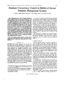
Every 5 minutes: Write prior samples Sample photo active Sample total solar Sample temperature Sample humidity
a sensornet OS to automatically minimize energy consumption without requiring additional explicit information from an application. The key insight behind ICEM is that the most important information a sensornet application can provide is the potential concurrency of its I/O. As most sensornet OSes are completely event-driven, an application simply needs to make a set of asynchronous system calls and let the OS schedule the underlying operations. The research challenge in ICEM lies in the fact that some operations must occur serially. While application-level requests can use a single API call, peripherals often have complex call/return sequences, some of which have tight timing constraints. This requires integrating traditional blocking synchronization primitives into an execution model that is completely non-blocking. ICEM solves this problem by carefully exposing low-level concurrency to drivers through power locks, a novel non-blocking lock mechanism that integrates concurrency, energy, and hardware configuration management. For example, when a client acquires a driver’s power lock, ICEM has powered and correctly configured the hardware for that client. When a power lock falls idle, ICEM powers down the underlying hardware. Power locks transform locks, a traditionally passive data structure, into an active energy management participant. We have designed and implemented ICEM as a key part of the second generation of the TinyOS operating system, TinyOS 2.0 (T2). It has been used to replace many of the ad-hoc policies and interfaces found in TinyOS 1.0 with three basic system abstractions and a small library of power lock components. We evaluate ICEM using a representative low duty cycle application that logs sensors every five minutes and sends data to a base station every twelve hours. Using ICEM, the application has a single line of power management code: it sets the radio duty cycle when it boots. ICEM achieves 98.4– 99.9% of the energy efficiency of a hand-tuned implementation that schedules I/O at the application level. The rest of this paper is structured as follows. In Section 2, we introduce a sample application that we use as an example throughout the rest of the paper and provide background information on wireless sensor energy profiles and operating systems. In Section 3, we introduce how ICEM divides device drivers into three concurrency classes and give their defining characteristics. In Section 4, we describe how drivers manage their concurrency and energy, describe power locks, and provide details of the supporting power management library. In Section 5 we evaluate ICEM using power traces of our sample application, runtime instrumentation of library calls, and a survey of where and and how often the different driver classes appear. We compare our approach to prior work and existing sensornet OSes in Section 6, provide insight into future developments in Section 7, and conclude in Section 8. Appendix A contains pointers to the TinyOS 2.0 ICEM source code.
2.
Figure 1: Application pseudocode. Every operation is non-blocking. Rather than try to coordinate sample completion, the loop writes the previous results to flash. Similarly, while it sends one set of samples it reads the next set from flash.
less sensors. Every five minutes, the application samples four sensors and logs the readings in flash with a sequence number. Each log record is ten bytes. Every twelve hours, the application retrieves new readings from flash and sends them to a gateway. The application logs values to flash to provide data reliability in case of temporary or long-term disconnection, a common problem in long-term deployments [35]. Sampling and sending are completely decoupled: the two parts have a producer/consumer relationship on the log. Data latencies of a day are acceptable for many low-rate environmental monitoring applications [33, 35]. If needed, the application can have a shorter reporting period, but an application saves energy by sending bursts rather than individual packets [23]. Low duty cycle sensornets generally reduce radio energy consumption with a technique called low-power listening (LPL) [25]. In low-power listening, nodes turn their radios on just long enough to detect a carrier on the channel. If it detects a carrier, then it keeps the radio on long enough to detect a packet. Because the LPL check period is much longer than a packet, a transmitter must send its first packet enough times for a receiver to have a chance to hear it. The transmitter stops sending once it receives a link-layer acknowledgment or a timeout of twice the check period. When a node receives a packet, it stays awake long enough to receive a second packet. Therefore, a packet burst amortizes the wakeup cost of the first packet over the follow-up packets. The LPL implementation used in this paper has a wake-up duration of 5ms: we configured the application to sample at 1Hz, giving the radio a 0.5% duty cycle when there is no communication.
2.2
Operating Systems
Packet bursts reduce how long the consumer part of the application stays awake when sending data to the base station. Concurrency reduces how long the producer part of the application stays awake when sampling. For each sample, the application needs to sample its four sensors and log the record to flash. Each of these operations is an I/O operation. Depending on the underlying hardware, the OS may be able to service some of them concurrently. To allow the OS to concurrently sample and log readings, the application keeps two sets of data buffers, one for the current period and one for the previous period. Figure 1 shows application pseudocode. To perform these five operations concurrently, an application must either use non-blocking calls or allocate one thread per call. To provide concurrency with limited RAM, sensor network OSes, such as Contiki [5], TinyOS [16], and SOS [12] generally take the first approach and have a single thread stack. In these OSes, every I/O and long-running system call is non-blocking and has a completion callback/upcall: there is no polling. For the rest of this paper, we use TinyOS and its programming language, nesC [7], as a representative example of these non-blocking operating systems. The split-phase operations these OSes provide are similar to traditional asynchronous I/O with one important difference: they know when an application is aware that an I/O operation has completed. In a threaded system, a device driver will resume threads blocked on select (or a similar function), but the scheduler may not run the
BACKGROUND
This section provides background on the challenges and details of managing energy on a wireless sensor. We start with a description of the sample application used as a running example throughout the rest of the paper. We describe the split-phase programming and concurrency model common to most sensornet OSes. We overview ultra-low power hardware characteristics and how they affect both driver implementations and sensornet energy management as a whole. From this information we observe that application concurrency gives a sensornet OS the ability to schedule operations in an energy efficient manner.
2.1
Every 12 hours: For all new log entries: Send current sample Read next sample
Application
Throughout this paper, we ground our goals and evaluation through a representative application of long lived, unattended wire2
Temp
MSP430
ADC
I2C
Humidity
SPI Radio
crocontroller implements three bus protocols – I2C, SPI, and UART – that all share a common set of I/O pins. Only one can be active at any given time, and the MSP430 has an intricate reset sequence for switching between them. The application’s digital sensors use a separate I2C bus. They do not share pins with the radio and flash chips SPI bus.
Total Solar Photo Active
Flash
2.4
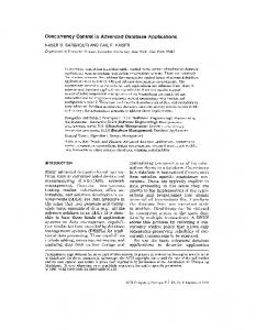
Figure 2: The application uses six peripherals: two SPI devices, two I2C sensors and two ADC sensors. The two I2C sensors are on the same chip (same I2C address), but require separate sensing command sequences.
thread immediately. In contrast, an application making split-phase I/O requests receives explicit notification from a device driver upon its completion through a direct upcall. This subtle but important difference allows a device driver to know exactly when an application has been notified about the completion of an I/O event. ICEM leverages this knowledge, using application I/O requests to precisely control a device’s power state.
2.3
Managing Energy
Many peripherals have significant wake-up times, which waste energy by drawing current without doing useful work. To optimize for energy, an OS must minimize how often it pays this cost. Scheduling I/O in bursts – whether it be ADC samples and powering up the reference voltage or sending packets and the need to wake up a receiver – amortizes this cost, reducing the average energy consumed per operation. Providing the intended workload as a set of concurrent requests allows the OS to use this application information to save energy. But as the examples above showed, some low-level I/Os must be serialized and some device drivers require simultaneous access to multiple peripherals. In these cases, if a driver could tell the OS that it requires exclusive access to a resource, it would provide both energy and concurrency management information. This request is essentially a lock, but as TinyOS is completely non-blocking, it must be a split-phase lock. Furthermore, granting the lock to a device driver may first require configuring hardware. For example, granting the SPI bus to a telos driver requires reconfiguring the USART into SPI mode. However, on other platforms, such as the mica family [15], the SPI has a dedicated set of pins. Making device drivers platform-independent requires encapsulating hardware configuration into the lock abstraction itself.
Hardware
We implemented our application in T2 on the telos platform. Telos has an 8MHz 16-bit CPU, a 250kbps 802.15.4 radio, a 2MB external flash, and 10kB of RAM [26]. Our telos nodes have humidity, temperature, photo active, and total solar sensors. When fully active, a telos node draws approximately 30mA of current. Its deepest sleep state draws 7-9µA. At a high level, two factors drive telos energy consumption. First, on a pair of AA batteries, a node has an active lifetime of just a few days. To last for months or years, a node must stretch this active time out by keeping its peripherals off and processor in a sleep state 99% of the time. Second, its microcontroller has a spectrum of low power states which keep different hardware resources powered. For example, a telos cannot drop to its 9µA sleep state when sampling an ADC sensor or using a bus. We defer detailed measurements of the telos’s power states and latencies to Section 5. Figure 2 shows how the six peripherals the application uses are attached to the microcontroller. There are several opportunities for concurrency. Two peripherals are digital sensors that use the I2C bus, and two are analog sensors that share the on-chip ADC. The OS can concurrently sample one digital and one analog sensor. The OS must arbitrate between sensors of the same kind. The flash and radio are both on the SPI bus, but the radio only needs the bus when loading a packet into transmit memory. Thus the OS can interleave flash reads and radio transmissions. Because the application schedules sensing and sending cycles independently, they can overlap and there can be up to seven outstanding I/O operations. An OS can schedule and interleave application-level I/O calls, but soft real-time requirements mean some device drivers need to limit concurrency so they can perform small atomic sets of split-phase operations. For example, when the CC2420 radio receives a packet, its driver needs to perform two separate reads over the SPI bus. The first read is for the physical layer length field, which it uses to determine how long the second read must be. Other drivers require exclusive access to multiple resources at once in order to operate properly. For example, the telos platform can configure its voltage reference to have different voltage levels; for some analog sensors, sampling requires not only exclusive access to the ADC but also to the voltage reference. Microcontrollers minimize pin counts to reduce leakage current and packaging size. Therefore, MCUs often reuse pins for multiple purposes. For example, the USART0 module on the MSP430 mi-
3.
ICEM DRIVERS
ICEM defines three broad concurrency classes: virtualized, dedicated, and shared. Figure 3 shows how the three differ in how they expose their concurrency to a user. This section presents the three classes in order of increasing complexity to the user. It gives concrete examples of when each class is used through the implementation of a stack for the radio used on most sensor nodes today. The next section describes how each class is implemented and how they work together to manage the overall power state of a sensor node.
3.1
Virtualized
Virtualized drivers are the simplest for a client to use: they have only a functional/data path. They support multiple users through implicit concurrency. Virtualized drivers buffer requests or otherwise maintain state in order to give each client the appearance of independence. It uses this per-client state to manage its concurrency, scheduling client requests in order to provide fairness or other desired properties. Because virtualized drivers can introduce latency, there is a tradeoff between simplicity and control. For this reason, application-level I/O interfaces are typically virtualized, while some lower-level ones are not. For example, a data-link packet sender is a virtualized driver. Each client can have a single outstanding packet. The packet layer buffers requests and services them with a round-robin policy, providing a limited (per-packet) form of fair queuing. Similarly, application-level millisecond timers are a virtualized driver. The driver implementation maintains per-client state, which it uses to schedule the underlying hardware timer in order to minimize the number of interrupts. Maintaining per-client state allows a virtualized driver to automatically control its power state. For example, when a virtualized 3
Virtualizer
Arbiter
Shared
Virtualized
Dedicated
Arbiter
Shared
Checked Shared
Unchecked Shared
Figure 3: ICEM’s three driver classes: virtualized, shared, and dedicated. The three squares mean that a component can support multiple clients: each client is an oval. Dedicated drivers have a functional interface as well an explicit power interface. Virtualized drivers provide implicit concurrency through a functional interface. Shared drivers provide explicit concurrency through a functional interface as well as a lock interface. Some shared drivers check client ownership, and some trust clients. Ovals are an instance of a client to a multi-client driver and a shaded box is an ICEM library component. Section 4.3 presents the details of the library. timer has no active timers and does not require a real-time clock, it disables interrupts and can stop the hardware counter.
3.2
Receiver
Dedicated
Data Link Layer
Dedicated drivers support a single user. Low-level hardware resources, such as counter/compare timer registers or a general purpose I/O (GPIO) pin have dedicated drivers. Additionally, the lowest level of most hardware independent abstractions, such as packet sending, are typically dedicated. They give their single user complete control over requests and energy management. While they do not have software concurrency, dedicated drivers can handle hardware concurrency. For example, the USART on the MSP430 family of microcontrollers has a one byte FIFO for transmission, and so a dedicated USART can handle two pending requests. In addition to a functional interface, dedicated drivers may provide an explicit power control interface. Not all dedicated drivers provide a power control interface, as sometimes power control is implicit in the functional interface. For example, enabling interrupts on a GPIO pin typically involves setting an enable bit in a control register: no additional on/off operations are needed.
3.3
GPIO
Receive
Control
SpiClient
SpiClient Send
Timer
Timer
SpiClient
Figure 4: The software structure of the CC2420 radio stack. It uses three SPI clients (shared), dedicated GPIO interrupts, one dedicated high-precision timer, one virtualized lower-precision timer, and provides a virtualized sending and receiving abstraction. Black lines represent data or functional interfaces, while grey lines represent control interfaces such as power or locking.
Shared
Shared drivers provide explicit concurrency. They support multiple users, but users must contend for the driver through a lock. Shared drivers are typically abstractions which require or benefit from a single client being able to perform an atomic series of operations. Shared drivers are also used when an operation requires exclusive access to multiple underlying resources at the same time. Calling commands on a shared driver without holding its lock is an error. Widely used shared drivers such as buses check that their lock is held by a caller, while narrowly used shared drivers such as an I/O pin driver assume those users are correct. Like virtualized drivers, shared drivers buffer client requests: both allocate per-client state. The difference lies in what requests are buffered. Virtualized drivers buffer functional requests (e.g., send a packet), while shared drivers buffer lock requests. Since the lock abstraction is common across all shared drivers, its implementation can be a library that many drivers reuse. As we discuss in the next section, as this library manages concurrency and pending requests it also manages a shared driver’s power state and configuration.
3.4
Sender
virtualizer sits on top of a dedicated abstraction, serializing requests to its single functional interface. As each sender has a single queue entry, the virtualizer gives each one a fair share of the packet transmissions. Protocols may and often do add additional queuing above. These virtualizations sit on top of dedicated abstractions of the send path, receive path, and control path. In addition to channel selection and transmit power, the dedicated control paths provide explicit power management interfaces. The dedicated layers use several drivers, including a dedicated timer for MAC backoff and acknowledgments, a shared bus for interacting with the radio chip, dedicated I/O pins, and a virtual timer for software IRQ on radio startup. The MAC timer is dedicated because it needs to be precise; the radio startup timer is virtualized because a bit of jitter when turning on the radio is acceptable. The bus is shared because, as noted in Section 2.3, multiple devices such as external flash chips and sensors use it, and because the radio must perform atomic command/response sequences.
Example: CC2420 Stack
4.
Figure 4 shows the component structure of an example complex implementation, the ChipCon CC2420 radio stack. The CC2420 is the dominant radio used in sensornets today, due to its relatively high bandwidth (250kbps), range (up to 100 meters), and IEEE standard frame format (802.15.4). At the top level, the CC2420 stack provides virtualized packet transmission and reception. When a client calls send(), the datalink layer virtualizer places the packet in its transmission queue. The
INTEGRATED MANAGEMENT
The goal of decomposing drivers into three classes is to provide a limited set of concurrency and power management models that can represent most sensornet devices. The prior section described how these driver classes appear to a user and distinguished when each class is typically used. This section describes how they are implemented and how ICEM integrates distributed peripheral energy management with centralized MCU sleep state control. 4
Default owner
4.1
Driver Energy Management
Power Power Manager
Default Lock
Arbiter
owner As Section 3 described, dedicated drivers leave all concurrency Power Power and energy management to their client. Dedicated drivers provide Arbiter Default Manager explicit energy control through one of three interfaces: StdControl ConfigureLock ownerArbiter (single-phase control), SplitControl (split-phase control) or AsyncArbiter (a) Arbiter. StdControl (single-phase control that is safe to call from within an Arbiter Default Configure interrupt handler). The lowest-level hardware abstractions are alConfigure owner Arbiter ways dedicated, as they represent a specific physical resource, andConfiguration Default Configure they typically provide the AsyncStdControl interface so they can owner HW-specific Configuration be called from code that needs immediate response to an interConfigure Power Power rupt. SplitControl and StdControl require going through the TinyOS HW-specific Manager Configure scheduler, which can introduce scheduling latencies. SplitControl is Lock for devices that require split-phase operations when powering on or (b) Configurator. (c) Power Manager. off: examples include peripherals that have warmup latencies, or peArbiter Figure 5: The three types of components in the ICEM library. Later ripherals whose power operations require using a shared device such Configure figures annotate interfaces with capital letters: L for Lock, D for as bus. StdControl is for devices that can be controlled immediately: Arbiterand HC for Default owner, P for Power, AC for Arbiter Configure, examples include on-chip systems such as the ADC or a counter. Configure Hardware Configure. Each caller of a parameterized interface (the Higher-level dedicated drivers, such as the radio, typically provide boxes) has a unique identifier that it passes in every call, so the callee Configuration StdControl or SplitControl. can distinguish callers. Virtualized and shared drivers integrate concurrency control HW-specific and energy management. Virtualized driver implementations are Configure interface-specific, as the interface they provide determines their rereceive another granted callback. Drivers that execute long or comquired buffering. A virtualized driver often has driver-specific power plex operations across several atomic actions often use a cooperative management logic, depending on what class of driver it sits on top scheduling approach, re-requesting a lock as soon as it is granted and of. The virtualizer is a central point of control: it is aware of all releasing it periodically. outstanding requests and the energy state of its underlying driver. Because TinyOS has a single stack, it has no threads. It therefore Shared drivers all have a common interface to their concurrency has no traditional OS concept of an execution context: there are no mechanism, a lock. As synchronization primitives have difficult long-running sequential code sequences with serialized operations. edge cases, designing shared drivers so they can share a lock impleTherefore, while code can request and release locks, answering the mentation leads to simpler and more robust implementations. Howquestion of who owns a lock is difficult. Our approach equates call ever, factoring concurrency out in this fashion complicates energy sites with clients: each lock in the system can have a unique set of management, as concurrency state is no longer directly available to candidate holders. This set is determined by which components have the driver. In practice, hardware devices underlying a shared abregistered with the lock interface. Unlike threads or objects, TinyOS straction need to be on when a client holds the lock and can be off components can only be created at compile-time. Therefore, a power when no-one holds the lock. The lock itself therefore has the knowllock’s candidate holder set is fixed at compile-time. edge necessary to manage the underlying device. Rather than being As power lock requests are non-blocking, a component can rea simple data structure or pushing complex state change callbacks quest several locks in parallel and proceed when they are all granted. into the core driver, the lock protecting a shared driver becomes an This of course raises deadlock concerns. As not all power locks active manager of the underlying hardware resource power states. grant in their request order and requests are non-blocking, requesting multiple locks in parallel does not specify a temporal order between 4.2 Split-phase Power Locks the requests. It is possible for two drivers to request a set of locks in ICEM supports shared drivers with power locks, synchronizathe same order and still encounter deadlock. In practice, we have yet tion primitives which couple energy, configuration, and concurrency to encounter a single deadlock bug in the T2 driver architecture due management. They couple energy and concurrency management by to how drivers are structured. As power locks usually protect hardturning devices off when the lock falls idle. They couple configuraware resources, there is typically a clear lock order encoded in the tion and concurrency management by allowing a client to specify a driver structure, and code reuse is a simple and easy way to maintain device configuration. Before an arbiter grants the lock to a client, it this order. Section 5.5 has one example of this, the light and temperapplies that client’s configuration. ature sensors of the MTS300 sensor board. Nevertheless, as drivers Traditionally, locks such as mutexes and semaphores are blockand the OS grow in complexity, deadlock avoidance and detection ing constructs that protect critical sections or shared data structures. may become a serious concern. We present ideas on how to address However, as TinyOS does not have blocking calls, its locks must be this problem in Section 7, noting that the complete lack of explicit split-phase. A component calls a function to request a power lock execution contexts may raise difficult challenges. and handles a callback when it acquires the lock. Systems whose timing is critical can try to avoid this split-phase operation when the 4.3 Component Library lock is idle using an immediate request. Immediate requests, like operations such as pthread_mutex_trylock() in traditional threaded Because power locks incorporate a queueing policy, a power management policy, and hardware configuration, ICEM provides a liOSs, return if the lock was acquired but do not enter a waiting queue brary of components that allow implementers of T2 device drivers if not: the typical code pattern is to issue a standard request if the immediate request fails. to easily combine small reusable building blocks into a complete Power locks use recursive requests as a yielding mechanism. If power lock implementation. The library has three types of components: arbiters, power managers, and configurators. Figure 5 shows a caller requests a lock when it already has a request pending, the these three classes of components and their interfaces. Clients prinrequest returns an error code. If a lock holder re-requests the lock, its request is enqueued: some time after releasing the lock it will cipally use the Lock interface.
5
4.3.1
sleep_state_t currentSleepState; bool dirtyMcuState;
Arbiters
Arbiters are a power lock’s core component. Arbiters provide a split-phase lock interface that arbitrates between outstanding requests for a resource. A power lock’s arbiter determines its request queueing policy. In addition to standard clients that use the Lock interface, arbiters can have at most one client which uses the DefaultOwner interface. A DefaultOwner cannot explicitly request the lock: instead, when the lock goes idle, the arbiter defaults it to this special client. In effect, a default client always has an implicit lock request that is lower priority than any other client: the arbiter automatically grants the lock to it when there are no other pending requests. Because the default client holds onto the lock whenever it is idle, the DefaultOwner interface has a callback to tell it when another client issues a request. In addition to the Lock and DefaultOwner interfaces, arbiters use the Configuration interface. Whenever the arbiter grants the lock to one of its clients, it calls the corresponding Configuration interface before signaling the granted callback to the client. If the client has not registered a Configuration implementation, it is a null call that the compiler prunes away. The component library has two arbiter policies, round robin and first come first served, which differ in their lock grant order and state requirements. In addition to full power locks, the library also includes simple versions, which do not include configuration or energy management. Section 5 evaluates the differences between the four arbiters.
4.3.2
void enterSleep(void) { disable_interrupts(); if (dirtyMcuState) { dirtyMcuState = FALSE; currentSleepState = mcuPowerState(); } setSleepState(MAX(currentSleepState, sleepHook())); atomically_enable_interrupts_and_sleep(); }
Figure 6: MCU sleep logic. The sleep state selection starts by a platform-specific function mcuPowerState that computes the lowest state that is safe based on set of devices that are currently enabled. To avoid unnecessary recomputing of the mcuPowerState every time sleep mode is entered, an (optional) dirtyMcuState bit can be set by any code that affects state checked by mcuPowerState. In the next step, the manager modulates the computed state with the application preferences that the manager receives via a special sleepHook function call.
4.4
Power locks integrate concurrency and energy management for system peripherals. The second part of an efficient energy management strategy is to control the sleep state of a node’s microcontroller. While a node’s microcontroller typically has a low current draw compared to peripherals such as the radio, over long time periods the cost can add up. For example, a telos node can last approximately two months with all of its peripherals off but its microcontroller active. A telos in its deepest sleep state can in theory last thirty years, far beyond the effective shelf life of most batteries. Microcontrollers typically have a spectrum of low power modes (LPMs) that support keeping different peripherals enabled. Computing the lowest safe power state of the microcontroller requires system-wide information on whether various peripherals are in use. This computation, however, can have complex dependencies, such that individual device drivers may not be able to judge their own power state. For example, many microcontrollers allow software to configure whether their lowest power clock is driven by an internal or external oscillator. Furthermore, calculating the lowest power state can be complex, as there are many cases to consider. As the OS may enter a sleep state after every interrupt and this computation must occur with interrupts disabled, it can become an interrupt handling rate bottleneck. ICEM addresses these challenges through three mechanisms. First, every microcontroller has a sleep function that calculates the lowest safe power state based on which interrupt sources and on-chip devices (such as ADCs) are enabled. Second, the OS keeps track of a dirty bit, and only computes the power state when the bit is set. Drivers set the dirty bit whenever they touch hardware that might change the sleep state. Finally, the sleep state computation has an override hook with which a driver can specify a minimum safe sleep state. The OS picks a sleep state whose enabled peripherals are the union of its calculation and this hook. The timer driver of the atmega128 is one example use of this hook. Some low power states of the atmega128 have a significant wakeup latency (a few ms). These latencies can disrupt a timer system that needs to service two interrupts in quick succession (e.g., a timer in 3ms and another in 4ms), as the second interrupt may be dropped. The timer driver registers an override hook such that it makes sure the processor stays in a fast wakeup sleep state in these cases. Figure 6 shows ICEM’s microcontroller power management logic in C-like pseudocode.
Power Managers
Power managers implement the DefaultOwner interface and use one of the explicit power control interfaces (StdControl, SplitControl, AsyncStdControl). A power manager specifies a power lock’s energy management policy. At boot, all power managers have control over a lock and all devices are powered down. When a power manager receives a callback from its arbiter that the lock has been requested, it takes this as a signal that the device needs to be used and must be powered up. Conversely, when a power manager receives the lock from its arbiter, it takes this as a signal that the device is idle and may be powered down again. Because power locks are split-phase, devices that require splitphase power control do not pose any particular challenge. Consider a power manager that sits on top of a dedicated driver with a SplitControl interface. When it receives a callback that a client has requested the lock, it calls SplitControl.start(). Some time later, the operation completes with the split-phase SplitControl.startDone() callback. In this callback, the power manager releases the power lock as the underlying hardware is now ready for use. The component library has two power manager policies, immediate and deferred. The former powers off a driver as soon as the lock falls idle, while the latter waits for a timeout. TinyOS has three different power control interfaces, causing there to be six power manager components.
4.3.3
Sleep Energy Management
Configurators
Configurators are part of a lock granting path. They implement the Configuration interface that arbiters use. Configurators are for when power lock clients have a code preamble which should execute before they perform any operations. Configurators allow clients to incorporate this logic into an arbiter. This is useful when many clients have the same code preamble: one implementation can serve them all. Configurators are device-specific and so are spread throughout the TinyOS code base. Currently, there are configurators for the Atmega128 ADC as well as the MSP430 ADC, SPI, USART, and I2C. 6
ROM Overhead Per Client
Current
Time
Power State
900
1.92mA 182µA 9µA 536µA
NA NA NA NA
NA NA NA NA
800
18.86mA 18.92mA
5ms 12ms-1s (LPL)
LPM3 LPM3
1.75mA 2.69mA 1.46mA 458µA 458µA
5ms 5ms 2ms 75ms 220ms
LPM1 LPM1 LPM1 LPM3 LPM3
700
Bytes
Device Microcontroller Active LPM1 LPM3 Vref On Radio Receive (LPL Check) Send (1 packet) (0dB) Flash Read Record Write Record Analog Sensors Humidity Sensor Temperature Sensor
FCFS+ RR+ FCFS RR
600 500 400 300 1
2
3
6
7
8
9
10 11 12 13 14 15
Figure 7: Arbiter program memory overhead as the number of clients increases.
Immediate PM Deferred PM
The set of power locks associated with the shared hardware resources, together with the microcontroller manager forms the basis for a comprehensive control of the power state of the hardware with minimum explicit run-time involvement from the application. As a result, ICEM has a decentralized energy management scheme that keeps the system as a whole in the lowest possible energy consumption state that guarantees safe servicing of the current workload.
RAM (bytes) Async Std Split 0 5 5 4 6 6
ROM (bytes) Async Std Split 0 188 188 358 412 412
Table 2: Memory overhead of using the power manager library components
operations we wrote microbenchmarks that repeatedly perform one operation in an infinite loop. To measure the average cost of a sleep state we used the power-state override of ICEM’s sleep state calculation. To measure the length of each operation we connected a node to an oscilloscope and measured the timing of changes in current draw. To the best of our knowledge, these are the first published measurements for current (revision B) telos nodes: prior results are either derived from datasheets [26] or for the revision A, which has different components [24]. These measurements differ from the values advertised in the telos datasheet, in some cases, such as the idle sleep current, by as much as 50%. Table 1 shows the results of these measurements. The processor values are reported for each power state and include leakage currents of platform peripherals such as sensors, USB, and flash. The peripheral values do not include the processor current draw; instead, they show the lowest power state the processor can enter while that peripheral is in use. This is LPM3 for the radio because the SPI bus is off except for a few hundred microseconds of radio commands. It is LPM1 for the flash because logging operations keep the SPI bus on. It is also LPM1 for the analog sensors because the ADC requires a clock source, while it is LPM3 for the two I2C sensors because the bus is in software on GPIO pins. Finally, the voltage reference requires a 17ms warmup time before it can be used.
EVALUATION
ICEM’s goal is to allow simple sensornet applications to achieve high energy efficiency. This section evaluates how well ICEM achieves these goals in four ways. First, it measures the power states of the telos node and microbenchmarks of the CPU, RAM, and ROM overhead of ICEM’s library components. Second, using these benchmarks and high-frequency current traces, it compares the energy consumption of our sample application implemented three ways: with ICEM, in a single-threaded model, and with hand-tuned application-specific power management. Third, it compares the complexity of the hand-tuned application with that built over ICEM, in terms of lines of code. Fourth, through examples and our implementation of the device drivers on four T2 platforms, it examines whether ICEM is flexible enough to handle most sensornet peripherals and general enough to be widely used.
5.1
5
Num Clients
Table 1: Current draw, duration, and the lowest MCU power state of the major components used in our example application on the telos platform.
5.
4
Microbenchmarks: Telos Energy
The instantaneous current draw of a telos node is a function of the microcontroller power state, whether the radio, flash and sensor peripherals are on, and what operations active peripherals are performing. Given a perfect measurement setup, the energy consumed by a node is proportional to the time integral of a trace of its current consumption. However, the three orders of magnitude difference in a node’s power states make it difficult to measure at this precision. A measurement circuit that can accurately measure µA sleep currents cannot measure mA active currents, and one that measures mA currents cannot measure µA currents due to circuit noise.1 We therefore follow the methodology of earlier low-power studies [23] by measuring the average current draws of specific sleep states and I/O operations using a precision multimeter. To measure the time to completion of an operation we wrote applications that performed an operation once and observed the changes in current draw on an oscilloscope. To measure the average power cost of I/O
5.2
Microbenchmarks: Power Lock Library
The measurements in Table 1 provide the basic means for calculating the energy costs of different I/O operations and sleep states. Using ICEM, an application can submit all of its I/O requests in parallel, allowing the OS to schedule them as it sees fit in order to minimize energy consumption. Compared to a hand-tuned implementation that optimally controls components from the application, ICEM adds overhead in three ways. First, the generalized library components use extra code space and RAM. Second, calls that sit on top of shared drivers must go through arbiters, which takes CPU cycles and therefore energy. Finally, ICEM drivers must be able to handle serialized requests, so must consider warmup times when deciding on a power down policy. As mentioned in Section 4.3.1, the ICEM library has four arbiter implementations, supporting two arbiter policies and two levels of complexity. The two policies are round-robin (RR) and first-come-
1 This is why precision digital multimeters have multiple precision settings.
7
300
300 FCFS RR
200 100
400
Grant Pop Release Post Request
200 100
Immediate Request
Queueing Request
Granted Request
Release
(a) Cycle counts of arbiter locking commands. The additional bars are the additional cycles a default client adds.
Async Std Split Async+ Std+ Split+
300 200 100 0
0
Dequeuing Release
Cycles
400
0
500
Breakdown of Granted Request
400
Cycles
Cycles
Arbiter Overhead
FCFS
RR
FCFS+
Immediate
RR+
(b) Cycle count breakdowns of power lock granting a non-queueing request.
Requested
Granted
(c) Cycle count overhead of using a power manager.
Figure 8: Cycle count overheads of common power lock operations. The telos processor runs at 4MHz.
Data Logging: EF lashW rite ET emp EHumidity EV ref EP hoto ET otalSolar ELP M 3 ELP M 1 Total per sample
= = = = = = = =
(5ms) · (2.69mA) (220ms) · (458µA) (75ms) · (458µA) (17µs) · (536µA) (2ms) · (1.46mA) (2ms) · (1.46mA) (286ms) · (9µA) (9ms) · (182µA)
Data Upload: EF lashRead ERadioP ream ERadioSend ELP M 3 ELP M 1 Total per send
= = = = =
144 · (5ms) · (1.75mA) (1000ms) · (18.92mA) 144 · (12ms) · (18.92mA) (2008ms) · (9µA) (720ms) · (182µA)
Listening: ELP Lcheck ELP M 3 Total per check
= =
(5ms) · 18.86mA (5ms) · (9µA)
Total per Day: Esample Esend ELP L EIdle Total
≈ ≈ ≈ ≈
(288 samples ) · (168µAs) day (2 sends ) · (53, 023µAs) day (86400 checks ) · (94.3µAs) day s (85878 day ) · (9µA)
first-served (FCFS). The former scans across the clients in a deterministic order, while the latter grants the power lock to clients in the order they requested it. For each policy, there is a full arbiter implementation that supports power management and a simplified one that does not (it has no default client). In the figures and the rest of the text, a plus (+) denotes a complete arbiter (e.g., RR+) while a lack of a plus (e.g., FCFS) denotes a simple arbiter. Additionally, when referring to power managers, a plus (+) denotes a deferred power manager (e.g. Async+) while a lack of a plus denotes an immediate power manager (e.g. Split). Figure 7 shows the code size of the four arbiters as the number of clients increases. Arbiters have an initial overhead of between 350 and 550 bytes for a single connected client, and this cost increases linearly with the number of clients. The dip between 6 and 7 clients is due to automatic inlining introduced by the compiler. For n clients, an FCFS arbiter uses 6 + n bytes of RAM and an RR arbiter uses 8 + d n8 e bytes: an FCFS maintains an array-based queue, while an RR maintains a bitmask of pending requests. Figure 8(a) shows the CPU cycle overhead of performing arbiter operations. The most expensive is the complete request-grant cycle, which takes 300-350 cycles (75 - 87µs). Full arbiters take longer because they must tell the default client to release the lock. Figure 8(b) shows where these cycles go. They are evenly spread across five parts: the request call, posting a task in the operating system to signal the grant, popping the request off the queue, and signaling the grant. The arbiter posts a task to prevent possible calling loops. Figure 8(c) shows the additional overhead that a power manager introduces for the three different dedicated driver power interfaces (AsyncStdControl, StdControl, and SplitControl). Adding power management can add up to an additional 400 cycles of overhead (100µs). Finally, Table 2 shows the ROM and RAM overhead of the different power managers. The telos platform uses immediate power managers for the bus and ADC and a deferred power manager for the voltage reference and flash chip. Because the voltage reference has a 17ms wakeup time, our implementation gives it a 20ms power-down timeout. Therefore, the ADC can service periodic requests with an interrequest interval less than 17ms, but if the interval is 20ms or longer, there is a 17ms lag on some requests.
(µAs) 13.45 100.76 34.35 9.112 2.92 2.92 2.574 1.638 ≈ 168 (µAs) 1260 18, 920 32, 694 18 131 ≈ 53, 023 (µAs) 94.3 0.045 ≈ 94.3 (µAs) 48,384 106,010 8,147,520 772,898 ≈ 9, 074, 830
Table 3: Per-day energy consumption of the hand-tuned implementation in µAs. A pair of AA batteries have approximately 2700mAh, or 9.72·109 µAs: a node with this duty cycle can last approximately 2.93 years on 2 AA batteries. With no listening a node could theoretically last 28.6 years, disregarding the shelf-life of the batteries.
5.3
Application Performance
The telos power and arbiter cycle count measurements allow us to quantify the energy consumption of four different implementations of the low-rate sampling application. The first is our ICEM implementation, whose pseudocode is in Figure 1. It uses decoupled sense and send timers and issues all I/O operations as a series of concurrent requests on top of ICEM. The second and third are single-threaded versions with blocking I/O calls so ICEM cannot use concurrency to 8
Figure 9: Oscilloscope trace of one sample period for our example sensornet application, with spikes and important events labeled. Issues with our measurement circuit means that the measured MCU current levels are approximately 800µA above the accurate measurements in Table 1.
95%
2.5
90%
2
85%
1.5
80% 75% 70% 0.01
Every 5 minutes: Every 12 hours: Turn on SPI bus Turn on SPI bus Turn on flash chip Turn on radio Turn on voltage reference Turn on flash chip Turn on I2C bus while (new readings): Log prior readings turn on SPI bus Start humidity sample send prior reading Wait 5ms for log get next reading Turn off flash chip wait 5ms for log Turn off SPI bus turn off SPI bus Wait 12ms for vref wait for send Turn on ADC Start total solar sample Wait 2ms for total solar Start photo active sample Wait 2ms for photo active Turn off ADC Turn off vref Wait 34ms for humidity Start temperature sample Wait 220ms for temperature Turn off I2C bus
3
1
ICEM Serial+ Serial0.1 1 Sampling Interval (min)
0.5
Ideal lifetime (years)
Lifetime (% of ideal)
100%
0 10
Figure 10: Node lifetime running the sampling application with different sampling periods and I/O scheduling approaches. The dark line is the expected lifetime of an ideal, hand-tuned application. The grey lines are the relative lifetimes of ICEM and two serialized (blocking) approaches. Serial+ is the optimal I/O ordering while Serial- is the worst-case ordering.
Figure 11: Pseudocode for the hand-tuned implementation.
1s and reporting to the base station every 144 samples. An ICEM node will have a lifetime between 98.4% and 99.9% of the handtuned implementation depending on the sampling period chosen. In comparison to the hand-tuned implementation, the ICEM version wastes energy in two ways. First, it spends time in active mode due to power lock overheads. Second, it has the timeout on the voltage reference, which the hand-tuned implementation knows to turn off immediately after the second ADC reading. In the sensing cycle, there are several arbiter operations, which all together are 1800 cycles per sample, for a total of 4100µAs per day. For sending, ICEM and the hand-tuned implementations perform identically. The deferred power manager for the flash chip consumes a small amount of energy with its timeout timer, but as this occurs very rarely and is less than a millisecond long, it is negligible. The single-threaded approach is significantly less efficient (between 83% and 96% in the best case); additionally, the order in which sensors are sampled has significant effects on its lifetime. This waste is predominantly because these implementations must serialize reading from the log and sending packets, leaving the radio idle for an additional 5ms per sample sent. There is also a small inefficiency in the sensing loop, as the threaded versions spend an additional 5ms in LPM1 as they cannot sample the ADC and write to the log concurrently. The dominance of the sending loop on energy consumption is reflected in Figure 10 as an increase in efficiency as the sampling/sending period is increased. The less often packets need to be sent, the less energy will be consumed in the process.
reduce energy usage. The two single-threaded versions differ in their sensor sampling order, which affects how often deferred drivers are powered on and off. The last version is a hand-tuned implementation which has no arbiter overhead and whose application logic optimally schedules I/O and component power states, Table 3 outlines energy usage per day for this hand-tuned version. ICEM’s effects are visible in the application-level sensing and sending logic. Figure 9 shows a power trace of the ICEM implementation on the sense-and-log step, detailing the relevant events corresponding to the ICEM pseudocode. “Write prior samples” corresponds to the log write and log timeout events. “Sample photo active” and “sample total solar” correspond to voltage reference warmup, analog samples, and voltage reference timeout events. “Sample temperature” and “sample humidity” correspond to events of similar names as well as the digital sensor timeout, which exists in case the digital sensor does not respond. The digital sensors, which must be serialized, dominate execution time. Figure 10 compares the expected lifetimes of the four implementations as the sampling period is varied. The y-axis on the right shows the absolute lifetime of the hand-tuned implementation, while the y-axis on the left shows the relative lifetimes of the other three implementations when compared to the ideal, hand-tuned one. Figure 10 shows that ICEM executes the application logic efficiently. The values in this figure assume an LPL check period of 9
Photo Client
ADC Client
L
ReadVirtualizer
Arbiter
ReadVirtualizer
D
Config HC
Atm128Adc
P
Photo
Power Manager
ADC Client
ning at a slower (and lower power) speed. Sensors typically only configure the channel and reference voltage. Figure 12 shows the component structure of the Atmega128 ADC driver. The ADC is a virtualized service that uses a round robin arbiter to service requests. To sample from the ADC, a program must instantiate an ADC client and provide a component that configures the ADC as needed. When a user of the client requests an ADC sample, the client requests the lock on the ADC from the arbiter and returns. When the lock is granted, the arbiter has automatically configured the ADC for a sample and the client requests a sample from the underlying ADC. When the ADC lock is idle, the arbiter powers down the ADC through the power manager, which clears the enable bit in the ADC control register. When the arbiter receives a lock request, it tells the power manager to turn on the ADC and the power manager sets the ADC enable bit.
Code Complexity
The major change from the ICEM to the hand-tuned application is the addition of code to explicitly control the power state of all peripherals, as shown in Figure 11. Written in nesC [7](the implementation language of TinyOS), the hand-tuned implementation is approximately 400 statements, with several edge cases due to the contention for the SPI bus between log reads, log writes, and packet transmissions. In contrast, the ICEM implementation is 68 nesC statements, most of whose complexity is in correctly dealing with the seek pointer in the log. Of those statements, only one deals with energy management: setting the LPL check period to be one second.
5.5.2
MTS300 Photo Sensor
The MTS300 is a sensor board for mica-family nodes. It has a large number of analog sensors, including magnetometers, accelerometers, a microphone, a temperature sensor and a light sensor. The large number of sensors mean that two of the sensors – the light and temperature sensors – share an ADC input channel. Each sensor uses a separate GPIO pin to provide a source voltage: controlling which sensor is sampled requires having only one of these two pins active. The sensors require approximately 20ms to stabilize after voltage is applied. We describe the photo (light) sensor driver here; the temperature sensor implementation is essentially identical except that it enables a different GPIO pin. A photo sensor is a virtualized service that sits on top of the Atmega128 ADC. A photo sample goes through three levels of arbitration. The first is the lock on the photo driver: only one photo client can sample at a time. The second is the lock on the shared ADC channel, which ensures only one of the photo and temperature drivers is active at any given time. Finally, the service must acquire the ADC lock through the Lock interface of its ADC client. Once it has all three locks, it can safely sample the sensor. Figure 13 shows the component structure of the MTS300 photo driver. When a client request a sample, the virtualizer requests the lock from the photo arbiter. The arbiter’s power policy turns on the photo driver with a split-phase call through a power manager. When turned on, the photo driver requests the lock on the ADC channel from the pin arbiter. When the pin arbiter grants the lock, the photo driver powers up the photo pin and starts a 20ms timer. When the timer fires, the driver indicates to the power manager that it is fully started, the photo arbiter grants the lock to the client, and the client
Example Drivers
For ICEM to be an effective architecture for sensor node device drivers, it must be able to handle the diverse peripherals that lowpower sensor nodes have. We have implemented drivers for five TinyOS platforms (mica2, mica2dot, micaZ, telos, and eyes) and three sensor boards (mts100, mts300, telos). This represents a total of 114 drivers: 52 dedicated, 21 shared, and 41 virtualized. Next we present four example device drivers in T2. All four have been in active use by the sensornet community for over a year. We chose these drivers because they highlight interesting requirements sensornet hardware can introduce and how our implementations use power locks to meet these requirements while providing simple API.
5.5.1
Photo Pin
Figure 13: Component architecture of the light sensor of the MTS300 sensor board for the Atmega128-based mica family of sensor nodes. The MTS300’s temperature sensor shares a pin with the light sensor, requiring two levels of arbitration.
The energy cost of LPL checks, however, cause the node lifetime to asymptotically approach about 3 years. In summary, these results show that with ICEM, power consumption is dominated by hardware (e.g., sleep mode consumption) and algorithmic issues (e.g., which sensors to sample or the choice of low-power-listening scheme) and not by low-level details of software implementation (e.g., which order sensors are sampled in). Finally, as suggested by Table 3, a device that enables low-power listening to receive messages at any time spends essentially all of its energy checking the radio channel for activity.
5.5
Pin Arbiter
L P
Figure 12: Component architecture of the analog-to-digital conversion driver on the atmega128 microcontroller. Dashed polygons represent components the client must instantiate or provide. For example, a component that uses the ADC must instantiate an ADC client and connect an ADC configurator.
5.4
D Power Manager
P
AC Adc
Light Arbiter
L
Atmega128 ADC
The Atmega128 microcontroller has an on-board 10-bit analogto-digital converter with 8 single-ended input channels. Configuring the Atmega128 to take a sample requires configuring three parameters: input channel, reference voltage source, and clock prescaler. The ADC can use either an internal 2.5V source or an IO pin for a reference voltage. The clock prescaler allows software to adjust the ratio between the ADC clock rate and the core clock frequency in order to maintain timing requirements when the processor is run10
BlockClient
I2C Client L
SPI Client
LogClient
Arbiter BlockTranslate
LogTranslate
AC I2C HC Msp430Usart
SPI
L
D
SectorVirtualizer
Power P Manager
P SpiClient
Figure 14: Partial component architecture of the USART driver on the MSP430 microcontroller. Different bus protocols (e.g., SPI and I2C) share the pins. When a client is granted the USART resource, the arbiter has automatically configured it for the proper protocol and speed. An example UART client is not shown.
D Power Manager
The power manager wires to the sector virtualizer rather than the SPI client because power state changes on the STM25P require sending commands to it. When the sector arbiter determines that there are no active clients, it gives the lock to the power manager, which tells the sector virtualizer to shut down the chip. The sector virtualizer acquires the lock on the SPI with its SPI client and sends the shutdown command to the STM25P.
MSP430 USART0
The MSP430 series microcontroller has two buses, USART0 and USART1. USART0 can be configured to act as an SPI, I2C, or UART. On sensor platforms such as telos and eyes, USART0 is shared among a large number of peripherals. For example, on telos nodes, USART0 is used as an SPI bus for the radio and flash chip and as an I2C bus for sensors. USART1 has similar but not identical functionality. Figure 14 shows the component structure of the USART stack. Unlike most other hardware resources, the MSP430 USART driver has multiple types of clients. Unlike the Atmega128 ADC stack, which has client-defined configurations, the USART clients have predefined configuration settings. While some USART peripherals need to configure the bus (e.g., run at a slower speed), this is rare. The USART clients are shared abstractions. Unlike the Atmega128 ADC, which virtualizes ADC samples, many peripheral drivers require performing a series of uninterrupted requests where the bus is held between each operation. Therefore the SPI, UART, and I2C clients export the Lock interface, providing users access to the underlying lock on the bus. The configuration components mean that when a client acquires the lock, the bus has already been automatically configured for that protocol. Finally, if no client requires the bus, it is powered down and its interrupts disabled.
5.5.4
Arbiter
Figure 15: Component architecture of the driver for the STM25P NOR flash chip used by the telos platform. The arrowhead distinguishes the wirings of the log and block clients, which are both clients of the underlying sector driver.
requests a sample. This request goes through the ADC virtualization process described in Section 5.5.1.
5.5.3
L
6.
RELATED WORK
ICEM borrows heavily from three large areas of prior work: concurrency control, energy management, and I/O scheduling. Each of these topics has made key observations which ICEM incorporates into its design and structure.
6.1
Concurrency Control
Traditional concurrency control deals with threads and blocking synchronization primitives such as locks, semaphores, barriers, and monitors [17]. The fundamental assumption in much of this work is that the underlying OS is itself threaded. In contrast, the eventdriven execution model typical to sensornet OSes has a single stack and requires split-phase synchronization primitives. For example, power locks grant a lock with a callback. Split-phase locks are not themselves new – the EARTH parallel model introduced them for use in SMP clusters [36] – but ICEM uses them in the low levels of an OS rather than in high performance parallel computing. In addition, TinyOS [16] contains several device-specific split-phase concurrency control interfaces, such as BusArbitration, which we took as a starting point in designing power locks. As there is no inherent CPU parallelism, nonblocking optimistic concurrency control algorithms [14] have limited utility. ICEM’s shared drivers also differ from many traditional synchronization primitives in that they export low-level locks to higher layers, providing explicit concurrency control across system boundaries. As power locks protect hardware resources rather than memory structures, they are generally not amenable to most traditional locking optimizations [27]. For example, given the cooperative scheduling typical of sensornet OSes, spin locks are useless. Similarly, as drivers rarely “read” hardware resources unless to modify their state, read/write locks do not provide significant benefits.
Storage
Figure 15 shows the component structure of the LogRead and BlockRead abstractions for the STM25P flash chip on the telos platform. BlockRead provides read/write operations on fixed-size and fixed-offset data units. Block storage is typically used for large data that needs random access, such as code or data downloads. Log storage is typically used for storing streams of sensor readings, and provide an append-only abstraction. Since NOR flash supports random access reads and writes, both log and block storage are implemented on top of a “sector” abstraction of the underlying chip. Because log and block present application-level units of reads and writes, they are virtualized services. Each block or log client has an associated sector client that it uses to read and write the chip. As the block and log drivers need to perform multiple underlying reads and writes for an operation, the sector interface is a shared abstraction. For example, when a log client requests to write a record, the driver tries to acquire the lock on the sector abstraction. When it acquires the lock, it writes a record, releases the lock, and signals completion to the application.
6.2
Energy Management
As laptops have grown in popularity, so has interest in improving their lifetime through energy management. Prior work towards this end has, for the most part, focused on individual devices, such as disks [4, 13], memory [21], or the CPU [10, 6]. Venkatachalam et al. 11
provide a very good survey of current and proposed approaches [37]. The basic challenge these systems face is inferring future application activity from prior requests. ICEM avoids this problem at low levels of the OS by promoting a nonblocking model and, where serialization is unavoidable, allowing drivers to specify their needs through power locks. ECOSystem takes these approaches one step further, incorporating energy has a first-class resource in OS scheduling [42, 43]. In the ECOSystem model, applications have units of energy called “currentcy,” which they spend as they use the CPU or peripherals. As ECOSystem is intended for a multitasking system, one key benefit currentcy provides is a common resource to enable fair-share scheduling across multiple system devices. The ICEM and ECOSystem approaches are completely complementary. ICEM operates at a much lower level in the system, optimizing energy consumption for whatever workload an application provides. An ECOSystem-like library layered on top of ICEM would allow solar-powered sensors such as Heliomote [28] and Prometheus [18] to maintain application quality of service as energy input changes. Symbian OS [31], used in many mobile phones, has a very similar approach to ECOSystem, except that it only accounts for energy use and does not enforce a desired system lifetime. Like most other embedded OSes, Symbian requires applications to explicitly control device power states. The Advanced Configuration and Power Interface (ACPI) [2] is an open industry specification for operating system-directed power management. ACPI’s logic requires dedicated peripheral hardware support that the simple, low-power chips common to embedded systems do not have.
6.3
should not be issued, while the latter wastes energy when it should. We are exploring how an application could provide information to the OS to guide scheduling decisions. Mechanisms such as I/O cancellation could provide sufficient information in many cases. As these workloads are inherently dependent on the environment, they will likely benefit from on-line estimation and learning techniques.
8.
Acknowledgements This work was supported by generous gifts from Intel Research, DoCoMo Capital, Foundation Capital, the National Science Foundation under grants #0615308 (“CSR-EHS”) and #0627126 (“NeTSNOSS”), and a Stanford Terman Fellowship. We would like to thank all members of the TinyOS Core Working Group, as well as the TinyOS community at large, for the contributions they made during the design process of this work. Special thanks are due to Joe Polastre and Cory Sharpe of Moteiv Co., and Jan Hauer from TU Berlin for the valuable insight and effort they provided during the early stages of this project.
I/O Scheduling
Over the past 50 years, operating systems have refined concurrency as a way to improve I/O performance. With many concurrent requests, disks can scan rather than seek [8], and network links can remain busy although each open sock set has significant timeouts and latencies [38]. In some cases, concurrency management goes one step further, filling idle periods with prefetching to speculatively improve future performance [9]. ICEM also uses concurrency to reduce system latencies, but for the purpose of reducing energy consumption rather than increasing performance. However, reducing system latencies and response times decreases how long a node has to be on, thereby improving system longevity.
7.
CONCLUSION
ICEM is a device driver architecture for fully event driven operating systems typical of ultra-low power sensornets. ICEM enables applications with no explicit energy management to operate within 1.6% of a hand-tuned optimal energy schedule. The key observation behind ICEM is that the most useful information an application can provide an OS for performing power management is the potential concurrency of its I/O operations. Using ICEM, application level concurrency allows the OS to save energy by efficiently scheduling I/O operations. While ICEM’s effectiveness questions the assumption that sensornet applications must be responsible for power management, what interface the OS should provide to applications remains an open question.
9.
REFERENCES
[1] H. Abrach, S. Bhatti, J. Carlson, H. Dai, J. Rose, A. Sheth, B. Shucker, J. Deng, and R. Han. MANTIS: System Support for MultimodAl NeTworks of In-situ Sensors. In 2nd ACM International Workshop on Wireless Sensor Networks and Applications (WSNA), 2003. [2] ACPI - Advanced configuration and power interface. http://www.acpi.info. [3] W. Archer, P. Levis, and J. Regehr. Interface contracts for tinyos. In Proceedings of the 6th International Conference on Information Processing in Sensor Networks (IPSN), 2007. [4] F. Douglis, P. Krishnan, and B. N. Bershad. Adaptive disk spin-down policies for mobile computers. In MLICS ’95: Proceedings of the 2nd Symposium on Mobile and Location-Independent Computing, pages 121–137, Berkeley, CA, USA, 1995. USENIX Association. [5] A. Dunkels, B. Grnvall, , and T. Voigt. Contiki - a lightweight and flexible operating system for tiny networked sensors. In Proceedings of the First IEEE Workshop on Embedded Networked Sensors 2004 (IEEE EmNetS-I), Nov. 2004. [6] K. Flautner and T. Mudge. Vertigo: automatic performance-setting for linux. In OSDI ’02: Proceedings of the 5th symposium on Operating systems design and implementation, pages 105–116, New York, NY, USA, 2002. ACM Press. [7] D. Gay, P. Levis, R. von Behren, M. Welsh, E. Brewer, and D. Culler. The nesC language: A holistic approach to networked embedded systems. In SIGPLAN Conference on Programming Language Design and Implementation (PLDI’03), June 2003. [8] R. Geist and S. Daniel. A continuum of disk scheduling algorithms. ACM Trans. Comput. Syst., 5(1):77–92, 1987. [9] R. A. Golding, P. B. II, C. Staelin, T. Sullivan, and J. Wilkes. Idleness is not sloth. In USENIX Winter, pages 201–212, 1995. [10] K. Govil, E. Chan, and H. Wasserman. Comparing algorithm for dynamic speed-setting of a low-power cpu. In MobiCom ’95: Proceedings of the 1st annual international conference on Mobile computing and networking, pages 13–25, New York, NY, USA, 1995. ACM Press. [11] D. Grunwald, P. Levis, C. Morrey, M. Neufeld, and K. Farkas. Policies for dynamic clock scheduling. In Proceedings of the 4th Symposium on Operating Systems Design and Implementation (OSDI), 2000.
FUTURE WORK
Going forward, we see two important areas of future work for ICEM. The first, as mentioned in Section 4.2, is compile-time analysis for detecting possible deadlocks. We believe that a static analysis using nesC interface contracts [3] will enable effective conservative deadlock detection. Contracts allow the build system to associate calls and completion callbacks, linking them together into a sequential series of operations. As T2 implements its tasks as interfaces, this approach can be easily incorporated into the OS concurrency model. This information allows the build system to generate a callgraph of concurrent operations in which any circular lock dependency indicates a possible deadlock. The second area of future work is conditional I/O. This paper focuses on workloads that are independent of the data collected. Sensornet applications, however, often want to send, sample, or store depending on the data values generated: TinySQL [22] queries such as SELECT light WHERE temp > 50 are a simple example. In the current model, the application can either issue all of the I/O calls in parallel and discard unwanted results or serialize its I/O calls to prevent unnecessary I/O. The former wastes energy when the I/O 12
[12] C.-C. Han, R. Kumar, R. Shea, E. Kohler, and M. Srivastava. A dynamic operating system for sensor nodes. In MobiSYS ’05: Proceedings of the 3rd international conference on Mobile systems, applications, and services, 2005. [13] D. P. Helmbold, D. D. E. Long, and B. Sherrod. A dynamic disk spin-down technique for mobile computing. In MobiCom ’96: Proceedings of the 2nd annual international conference on Mobile computing and networking, pages 130–142, New York, NY, USA, 1996. ACM Press. [14] M. Herlihy, V. Luchangco, P. Martin, and M. Moir. Dynamic-sized lock-free data structures. In PODC ’02: Proceedings of the twenty-first annual symposium on Principles of distributed computing, pages 131–131, New York, NY, USA, 2002. ACM Press. [15] J. Hill and D. E. Culler. Mica: a wireless platform for deeply embedded networks. IEEE Micro, 22(6):12–24, nov/dec 2002. [16] J. Hill, R. Szewczyk, A. Woo, S. Hollar, D. E. Culler, and K. S. J. Pister. System Architecture Directions for Networked Sensors. In Architectural Support for Programming Languages and Operating Systems, pages 93–104, 2000. TinyOS is available at http://webs.cs.berkeley.edu. [17] C. A. R. Hoare. Monitors: an operating system structuring concept. Commun. ACM, 17(10):549–557, 1974. [18] X. Jiang, J. Polastre, and D. Culler. Perpetual environmentally powered sensor networks. In IPSN ’05: Proceedings of the 4th international symposium on Information processing in sensor networks, page 65, Piscataway, NJ, USA, 2005. IEEE Press. [19] K. Klues, V. Handziski, J.-H. Hauer, and P. Levis. TEP 115: Power Management of Non-Virtualised Devices. http://www.tinyos.net/tinyos-2.x/doc/txt/tep115.txt, 2007. [20] K. Klues, P. Levis, D. Gay, D. Culler, and V. Handziski. TEP 108: Resource Arbitration. http://www.tinyos.net/tinyos-2.x/doc/txt/tep108.txt, 2007. [21] A. R. Lebeck, X. Fan, H. Zeng, and C. Ellis. Power aware page allocation. In ASPLOS-IX: Proceedings of the ninth international conference on Architectural support for programming languages and operating systems, pages 105–116, New York, NY, USA, 2000. ACM Press. [22] S. R. Madden, M. J. Franklin, J. M. Hellerstein, and W. Hong. TAG: a Tiny AGgregation Service for Ad-Hoc Sensor Networks. In Proceedings of the ACM Symposium on Operating System Design and Implementation (OSDI), Dec. 2002. [23] G. Mathur, P. Desnoyers, D. Ganesan, and P. Shenoy. Ultra-low power data storage for sensor networks. In IPSN ’06: Proceedings of the fifth international conference on Information processing in sensor networks, pages 374–381, New York, NY, USA, 2006. ACM Press. [24] A. Milenkovic, M. Milenkovic, E. Jovanov, D. Hite, and D. Raskovic. An environment for runtime power monitoring of wireless sensor network platforms. In Proceedings of the 37th IEEE Southeastern Symposium on System Theory (SSST’05), 2005. [25] J. Polastre, J. Hill, and D. Culler. Versatile low power media access for wireless sensor networks. In Proceedings of the Second ACM Conferences on Embedded Networked Sensor Systems (SenSys), 2004. [26] J. Polastre, R. Szewczyk, and D. Culler. Telos: enabling ultra-low power wireless research. In IPSN ’05: Proceedings of the 4th international symposium on Information processing in sensor networks, page 48, Piscataway, NJ, USA, 2005. IEEE Press. [27] M. L. Powell, S. R. Kleiman, S. Barton, D. Shah, D. Stein, and M. Weeks. SunOS multi-thread architecture. In Proceedings of theWinter 1991 USENIX Technical Conference and Exhibition, pages 65–80, Dallas, TX, USA, 1991. [28] V. Raghunathan, A. Kansal, J. Hsu, J. Friedman, and M. Srivastava. Design considerations for solar energy harvesting wireless embedded systems. In IPSN ’05: Proceedings of the 4th international symposium on Information processing in sensor networks, page 64, Piscataway, NJ, USA, 2005. IEEE Press. [29] Red Hat, Inc. eCos v2.0 Embedded Operating System. http://sources.redhat.com/ecos. [30] SourceForge. TinyOS CVS Repository. http://sourceforge.net/cvs/?group_id=28656. [31] Symbian. Symbian OS - the mobile operating system. http://www.symbian.com/. [32] R. Szewczyk, P. Levis, M. Turon, L. Nachman, P. Buonadonna, and V. Handziski. TEP 112: Microcontroller Power Management. http://www.tinyos.net/tinyos-2.x/doc/txt/tep112.txt, 2007. [33] R. Szewczyk, J. Polastre, A. Mainwaring, and D. Culler. An analysis of a large scale habitat monitoring application. In Proceedings of the Second ACM Conference on Embedded Networked Sensor Systems (SenSys 2004), 2004. [34] TinyOS Alliance. TinyOS Community Forum: An open-source OS for the networked sensor regime. http://www.tinyos.net. [35] G. Tolle, J. Polastre, R. Szewczyk, D. Culler, N. Turner, K. Tu, S. Burgess, T. Dawson, P. Buonadonna, D. Gay, and W. Hong. A macroscope in the redwoods. In Proceedings of the Third ACM Conference on Embedded Networked Sensor Systems (SenSys 2005), Nov. 2005. [36] G. Tremblay, C. J. Morrone, J. N. Amaral, and G. R. Gao. Implementation of the
[37] [38]
[39] [40] [41]
[42]
[43]
earth programming model on smp clusters: a multi-threaded language and runtime system. Concurrency and Computation: Practice and Experience, 15(9):821–844, 2003. V. Venkatachalam and M. Franz. Power reduction techniques for microprocessor systems. ACM Computing Surveys, 37(3):195–237, 2005. R. von Behren, J. Condit, F. Zhou, G. C. Necula, and E. Brewer. Capriccio: scalable threads for internet services. In SOSP ’03: Proceedings of the nineteenth ACM symposium on Operating systems principles, pages 268–281, New York, NY, USA, 2003. ACM Press. A. Weissel, B. Beutel, and F. Bellosa. Cooperative i/o: a novel i/o semantics for energy-aware applications. SIGOPS Oper. Syst. Rev., 36(SI):117–129, 2002. Wind River Systems, Inc. VxWorks 5.4 Datasheet. http: //www.windriver.com/products/html/vxwks54_ds.html. W. Yuan and K. Nahrstedt. Energy-efficient soft real-time cpu scheduling for mobile multimedia systems. In Proceedings of the Nineteenth ACM Symposium on Operating Systems Principles (SOSP), pages 149–163, New York, NY, USA, 2003. ACM Press. H. Zeng, C. S. Ellis, A. R. Lebeck, and A. Vahdat. Ecosystem: managing energy as a first class operating system resource. In ASPLOS-X: Proceedings of the 10th international conference on Architectural support for programming languages and operating systems, pages 123–132, New York, NY, USA, 2002. ACM Press. H. Zeng, C. S. Ellis, A. R. Lebeck, and A. Vahdat. Currentcy: A unifying abstraction for expressing energy. In Proceedings of the Usenix Annual Technical Conference, June 2003.
APPENDIX A. SOURCE CODE ICEM has been implemented as a core component of TinyOS 2.0 (T2). Source code for the interfaces, MCU sleep logic, library components, and example device drivers exist for versions 2.0.1 and beyond. This code can be downloaded from the TinyOS sourceforge project [30] or from the TinyOS Alliance website [34]. Some of the components and interfaces have different names in the source code than they do in this paper, due to historical reasons and a desire for greater clarity. In the code, the Lock interface is named Resource, the Arbiter Configure interface is named ResourceConfigure, and the DefaultOwner interface is named ResourceDefaultOwner. The implementation of the components shown in Figures 12– 15 also have slightly different names than their implementations. The following directories contain all of the library components and interfaces introduced in this paper: • tinyos-2.x/tos/interfaces • tinyos-2.x/tos/lib/power • tinyos-2.x/tos/system The four example drivers and the CC2420 stack shown in Figure 4 can be found in these directories: • Atmega128 ADC: tos/chips/atm128/adc • MTS300 Photo: tos/sensorboards/mts300 • MSP430 USART0: tos/chips/msp430/usart • Storage: tos/chips/stm25p • CC2420: tos/chips/cc2420 The CC2420 figure refers only to source code for the radio stack in versions 2.0 and 2.0.1. More recently the stack has changed slightly to better support low power listening. Finally, technical documentation for the systems described in this paper can be found in TinyOS Enhancement Proposals (TEPs). TEP 108 [20] describes power locks, TEP 112 [32] documents the MCU sleep code, and TEP 115 [19] details power managers and their corresponding interfaces.
13